#using RF transmitters
Explore tagged Tumblr posts
Visit Tumblr Blog
Explore Tumblr blogs with no restrictions, modern design and the best experience.
Last Seen Tumblr Blogs


Fun Fact
Average visit duration of Tumblr.com is 10 mins and 25 secs.
Note
Ah yes very cool! My realm is ships 🥰 Same team tho! 🥰
With the title "anarcho electrificationism", it may be of interest for you to know that I actually work within the field of electrification. You're right for what you believe in and I'm rooting for you to join the fight when you start your career 💯 🥰💪
Well that is Specifically referring to Traction Electrification for Railroads, Streetcars, and Trolleybuses which is infact related to what I hope to do as I want to work in engineering
#I work on ship-to-shore communication#using RF transmitters#receivers#and associated control systems#to make sure big-ol girls can charge
3 notes
·
View notes
Text
Valiant
(Original post, Chapter 1)
Chapter 2
"Ellie!"
I blink awake. It's dark, the lighting hasn't switched over to morning mode yet and the sky is still black through the warehouse skylights. In fact, the only light is the gentle blue-white from Val's core. The indicator lights from the diagnostic equipment I have set up are completely dark.
I feel a spike of panic. A black out could mean any number of things, from benign to literal end of the world.
"What's going on?" I ask, fighting my grogginess. "What time is it?"
"I have lost external network connection. My internal clock indicates that it is 2:36:74," she says. Her voice is tinny and distant, likely the embedded speaker that I've managed to patch up.
"Ellie, I am sorry," she says. Her tone is distressed and contrite. She continues in a rush, "local wildlife nested amidst the network antenna and I attempted to relocate the nest. However in the process, I have accidently shorted the main high power bus with my drone peripheral."
Ah. That explains that. She probably tripped the main breaker. It's a terrible design and I've been meaning to add some resiliency, but that keeps getting out prioritized.
"Ellie, I am sorry," she repeats. "I have committed a mistake and I have inconvenienced you."
What?
Oh…
She's having the equivalent of a panic attack. She is a hyper intelligent AI core designed for fleet coordination and battle modeling, where failure to follow orders and standard operating procedure costs lives. This comes with a lot of built in anxiety. I understand that modern starships are less prone to such things, but when she was commissioned, the goal was to produce many warships very quickly. They were ultimately meant to be disposable, which led to some programming shortcuts.
"Hey," I say softly. "Are you okay? That's all I care about right now."
I roll out of my hammock and press my body against the surface of her core so that she can feel the plasmic discharge induced by my contact.
"I am well," she replies, her voice still small and panicked. "My core is isolated from main power. I can provide full diagnostics if you desire."
"No, that's okay. I'm glad you're alright. Should we see what we can do to take care of this?"
"Yes, please…"
She pauses.
"I do not like being disconnected. I… do not like the dark."
My heart breaks a little. Eighty-seven years, that's how long she was alone before I found her. An AI like hers can enter low power mode, but that is still an unfathomably long time. Units like her were never meant to be alone.
I reluctantly disengage from her core.
"I have to go outside," I tell her. She knows this, but I'm hoping it helps to talk through the process. "I'm going to get the headset working, so I'll be able to stay in contact, okay?"
"Thank you"
I pat the surface of her core gently before checking the rf transmitter I rigged up at her access port. It's short range, but it runs on her internal power. We used it a lot before I got her connected to internal and external networks, pretty much for this exact purpose, so I could talk to her without being right next to the core.
Connection looks good. I slip on the ear piece.
"Hey, can you hear me?"
"Yes, I can hear you Ellie," she replies.
Her voice through the earpiece is warm and smooth, even under the panic. It's her chosen choice and… well, it makes me feel��� okay, I'll just say it, it's a very sexy voice. The speaker mounted on the access panel doesn't really convey the full timbre of it. Needless to say, I was blown away the first time I heard it in high fidelity.
I think I might be in love with her.
There's a lot to unpack there, but there's no point in denying that the feelings exist.
I throw on a sweater and a spare pair of boots and make my way up the scaffolding that leads to roof access. About halfway there, I pause for a moment to catch my breath. I chance a look down and my breath is stolen from me.
This room, this entire building, is a warehouse built for a machine of war to be abandoned and forgotten.
It's a squat for a scavenger trying to eke out an existence on the fringes.
"You're beautiful," I whisper.
It is a cathedral. It is a temple built for a goddess and her priestess.
Here in the dark, lit only by the radiation of her core, the space seems infinite.
Her core flickers in response, but she doesn't say anything. She might be embarrassed. She might never have heard those words before and doesn't know how to respond. She doesn't need to. I don't know if she feels the same about me. I'm not even sure if I should want her to. I would hate for her to feel obligated to return my affection solely by the fact that I am the only one who cares enough to repair her. I started this project because I couldn't bear the thought of her suffering alone in darkness, any romantic feelings I have are incidental... mostly.
I continue my scent and finally arrive at the roof access. The door opens with a squeal and I step into the frigid night.
"Oh!" I gasp.
"Ellie?" Val asks in my ear after a moment, worry creeping into her voice. "Are you well?"
"Oh, sorry…" I reply. "It's the stars. The high altitude haze from that dust storm last week has finally cleared. It's… spectacular."
There's a pause.
"Would you describe them for me?" she asks plaintively.
"Uh, sure… but I'm not sure if I can do it justice. Well, there's the glow from the industrial district, but it's not too bad tonight. We've got the arc of the Milky Way pretty much directly overhead. And there's like the fuzzy haze of the planetary disk. Looks like one of the ice giants too. And… well, stars. Thousands of them, just crystal clear."
I locate the main antenna and, sure enough, the drone is tangled up with the main power lines. It looks like there might have been some thin insulation that arced. The spidery drone itself might be salvageable. It is clutching an unfortunately empty nest in its manipulators, whatever wildlife must have fled when she disturbed it. The drone's head is tilted curiously back in a way that I don't think it's fully explainable by arcing.
"Wait, were you out here stargazing?
"The ocular system on the drone peripheral lacks the resolution and focal length to resolve individual stars."
It's not an answer and she sounds very vaguely guilty.
"It's alright if you were," I tell her as I bend down to examine the power conduits. "And I can see if I can get you a better camera system up here. Maybe something telescopic."
"I would not want to inconvenience you," she replies.
"Val, you're allowed to want things," I sigh.
She's quiet for a long moment while I move the drone and begin repairs on the power conduit.
"I miss the stars," she says finally. "There are many things I wish to forget about my past. Being alone amidst the stars was one of my few comforts."
I consider this. It's the most she's ever told me about her past. I've seen the diagnostic logs of her positronic activity indicating distress. Her equivalent of nightmares.
"You know any good stories about them?" I ask.
"I do not understand the nature of your query."
"I don't know," I say with a shrug. "I guess I'm just curious if you have any favorites or if you have any interesting facts in your database.
I'm not really sure how I expect her to respond. I just want to get her talking and not dwell on being trapped in the dark or feeling guilty about causing it.
"There is a star," she begins tentatively, "which according to local charts and my estimate of local time, should be located at azimuth 146.7, elevation 25.4. It is the brightest star in the southern sky, do you see it?"
I'm honestly surprised by this, and it takes me a minute to orient myself and find it.
"Yeah, the bright blue one?"
"Yes!" she replies, and as she speaks she gets more animated - her tone brightens and her cadence picks up. "Epsilon Orionis, Hipparcos 26311, also known as Alnilam. It is the central star of the asterism as viewed from Earth known as Orion's belt. It is among the brightest stars visible from this region of space. During first wave colonization, it was erroneously back translated to Al-Nilam, the Sapphire. Local neo-folkloric tradition associates it with either a maiden or queen…"
She continues on like that, and I find myself absolutely fascinated as I work. The detail is very encyclopedic, but there are aspects of it that she can't possibly have obtained from just a star chart. I quickly come to the realization that she must have sought out details about the folklore and mythology on her own.
This was a hobby of hers. There's no question in my mind now that I have to obtain a better system to facilitate her stargazing.
I finish the patch job on the conduit and heft the drone over my shoulder while she continues. I only interrupt her when I arrive back at the high power breaker.
The night lighting comes back up and she practically sighs with relief as she reconnects with the external network. I wearily drag myself back to my hammock.
"Ellie, I'm sorry to have woken you and taken up so much of your time," she says.
I sigh and press my hand to the surface of her core.
"It's okay, really," I tell her. "I'm here for you."
"Thank you for listening to me," she says, bringing a smile to my face.
"Goodnight, Val."
"Goodnight, Ellie."
I almost say "I love you". I want to.
64 notes
·
View notes
Text
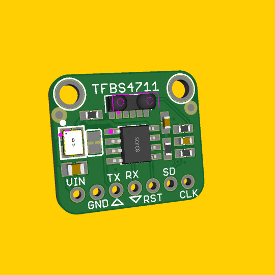
IrDA codec board 🔧📡🕰️
We've been designing all sorts of IR transmitters and receivers for the Adafruit shop lately, and a chance discussion got us thinking about IrDA - an old wireless protocol used in some PDAs, watches, laptops and toys. its not used anymore - bluetooth LE does a way better job - but there's probably some cases where IrDA hacking could be useful such as communicating with retro devices or if you want an RF-less wireless link. here's a board that combines a TFBS4711 transceiver (https://www.digikey.com/short/jn43cz31) with a MCP2112 codec (https://www.digikey.com/short/m8tp3708). you can communicate at 115.2kbps with RX and TX lines just like any UART. 115.2kbps is the standard baudrate. or, provide your own CLK for something like 9600 baud.
#adafruit#irda#ir#wirelessprotocol#retrotech#uartcommunication#electronicsdiy#communicationspeed#tfbs4711#mcp2112#hackoldtech#nostalgiatech#rfcommunication
11 notes
·
View notes
Note
Hey I have one of those little tvs too howd u do the broadcast setup
I've been trying to research how it works but a lot of the technical details confuse me
required equipment: RF modulator with correct format for your TV (PAL for european, NTSC for north american/japanese), HDMI to AV downscaler (unless you're using a device with AV output for the stream source, or your RF modulator has HDMI input), TV antenna (i just used a little pair of rabbit ears from target), and, optional but recommended: signal amplifier. and of course a tv with an antenna.
connect your TV antenna and optional amplifier to the RF modulator's output - normally you would use a coaxial cable to connect this directly to the TV's antenna input, but in this case we're being silly and sending the signal over the air instead, which it is not designed for.

connect your source device (i'm using a roku) to the HDMI downscaler if necessary. then, connect the downscaler (or the source device if not using a downscaler) to the RF modulator's input.
plug in any devices that need external power, and then tune your TV to the channel the RF modulator is set to - on NTSC modulators, this is usually by default channel 3 or 4. the one i'm using defaults to whatever it was set to last, which was NTSC 14.

enjoy your low fidelity! using this setup WITH the amplifier the broadcast range is about 3 feet, but it drops off significantly over one foot away. if you used a real transmitter the results would be better. but we're not doing that.

8 notes
·
View notes
Text
Rambly FYP post very stream-of-conciousness:
So, final year project update. Reframing the project as developing a selective beamforming scheme, based on prior works like OABF (on-off adaptive beamforming). There's some good literature that I need to chew through, so hopefully i can get my attention to stay on it long enough.
Current state is: I have a working adaptive beamformer, using particle swarm optimisation to change antenna element complex weights to form the far-field array factor that I want (treating elements as isotropic transmitters). It's convergence is a little funny, I need to verify that the particles are behaving in the way I want.
Next step is the introduction of the element selection (into groups of tiles). Elements with similar complex weights are grouped together. In a real antenna, these element groups are driven by the same RF chain (analogue phase shifers, feeding into individual RF amplifiers). This technique, while not producing optimal results, should (hopefully) produce adequate adaptive beamforming, with a reduced number of RF chains. The benefit of this is reduction of cost and complexity of the overall system.
Generally, I'm seeing some decent results and getting well into a good implementation. My next task is to define some figures of merit I can use to compare my technique to prior art (various LMS impls., MVDR, OABF, etc.) I've got some technical limitations, writing the simulator myself, so there's some interesting challenges here.
Antennas are cool and all but I still wanna do fusion instead. gaugh.
4 notes
·
View notes
Text
This RF Transmitter and Receiver module can be used with 433Mhz RF Radio modules for better communication and to avoid cross-connection with other transmitters and receiver modules working at the same radio frequency. This RF Transmitter Module uses the HT12E IC for encoding the message and the RF Receiver Module uses the HT12D IC for decoding.
3 notes
·
View notes
Text
the tech tree for literally every part of modern life is terrifyingly complex.
A desktop computer is made up of a case, a motherboard, power supply, a cpu, a video card (maybe), RAM, storage, fans, speaker, webcam, mouse, keyboard.... but every one of those components has subcomponents, there are circuitboards and rf or wifi or bluetooth transmitters in a lot of the mice and keyboards, the individual keys, the shells. The motherboard has thousands of subcomponents. The CPU is so complex that it defies imagining without a WHOLE lot of teaching. The graphics card is practically a computer all by itself. And right now, almost every new high end computer in the world is relying on a single company's chips (and it's not Intel). It's based in Taiwan. Taiwan is using that fact to help protect themselves from China.
Every component is a mix of materials ranging from sand to rare metals and these are not things you can just bootstrap in a few years, they all have been developed over decades from supply chain to manufacturing technique, you need machines capable of the level of precision to manufacture the machines with the level of precision...
But like, every cell phone is nearly as complex, only smaller.
Every new car these days has a computer or six onboard.
Every refrigerator, oven, microwave, washing machine....
We are so interdependent.
watch PearlMania500's response, that guy gets supply chain. I work in supply chain and that is exactly what everyone should be thinking about
But no, most people don't even know how their food gets to the grocery store
17K notes
·
View notes
Text
Behind the Circuits: Why NSN 5960-00-052-3289 Is Still in High Demand
In the highly technical world of electronic systems, even the smallest component can be the linchpin that ensures mission success or operational failure. One such quietly essential part is the 5960-00-052-3289, a National Stock Number (NSN) that continues to serve high-stakes industries with steadfast reliability.
What Exactly Is NSN 5960-00-052-3289?
The NSN 5960-00-052-3289 is categorized under Federal Supply Class (FSC) 5960, which includes Electron Tubes and Associated Hardware. While the average consumer may associate electron tubes with retro technology, the reality is far more nuanced. This particular NSN represents a specialized vacuum tube—a component known for handling high-frequency signals, voltage amplification, and high-temperature tolerance where semiconductors often fall short.
These aren’t outdated relics—they are critical components engineered to withstand extreme operational environments, still relied upon by modern defense and aerospace systems around the world.
Applications That Call for Precision and Power
While many electronic components have shifted to silicon-based alternatives, certain industries and applications still depend on the proven performance of vacuum tubes like the 5960-00-052-3289:
Military Radar Systems: Its ability to perform consistently under extreme duress makes it perfect for mission-critical communications and detection systems.
Aerospace Electronics: From control systems to communications, this NSN finds its place in aircraft requiring legacy support and high-frequency operations.
Industrial RF Equipment: High-power RF amplifiers in manufacturing or scientific facilities often require electron tubes for specific performance metrics.
Broadcast Transmitters: Some high-frequency transmission systems, particularly those used in remote or rugged areas, rely on tubes for their unmatched amplification strength.
These tubes are not just spare parts—they’re strategic assets that support everything from defense operations to essential communication infrastructures.
The Industries That Count on It
Industries that operate in high-risk, high-performance environments consistently rely on NSN 5960-00-052-3289 to meet operational standards. From government defense contractors to aerospace OEMs and critical infrastructure operators, the need for components that won’t fail under pressure is ever-present.
#chipsonsale#durablecomponents#electricalsystems#efficientfunctionality#trustedcomponents#longlastingparts#reliableperformance#reliableparts#highqualitycomponents#electrontube
0 notes
Text
Global Vacuum Capacitor Market Forecast to Grow at 4.4% CAGR Through 2031

The global vacuum capacitor market is projected to rise from a valuation of USD 567.8 million in 2022 to USD 827.6 million by the end of 2031, representing a compound annual growth rate (CAGR) of 4.4% between 2023 and 2031. Analysts point to surging demand in wireless communications, semiconductor manufacturing, materials processing, and aerospace as key growth drivers for these high-performance components.
Market Overview: Vacuum capacitors are specialized high‑voltage capacitors that utilize a vacuum as the dielectric medium. Their intrinsic ability to withstand extreme voltages, coupled with stable capacitance over a broad range of frequencies, makes them indispensable for radio frequency (RF) amplifiers, broadcast transmitters, plasma generation systems, and high‑energy physics experiments. Available in both fixed and variable configurations, vacuum capacitors cater to applications demanding precision tuning, low losses, and robust performance under high‑power conditions.
Market Drivers & Trends
5G and Next‑Generation Wireless: The rollout of 5G networks and preparation for 6G have intensified the need for precise RF tuning and impedance matching. Vacuum capacitors ensure minimal signal loss and tight tolerances in base stations, repeaters, and transmitters.
Semiconductor Fabrication: Rapid proliferation of devices from smartphones to electric vehicles drives semiconductor manufacturing expansion. Advanced processes such as extreme ultraviolet lithography (EUV) and FinFET transistor fabrication rely on RF plasma etching and deposition tools, where vacuum capacitors are critical for stable power delivery.
Industrial Plasma Systems: Materials processing (e.g., coating, welding, cleaning) uses high‑power RF generators for plasma generation. Vacuum capacitors maintain efficient power coupling and process stability.
Aerospace & Defense: Satellite transponders and radar systems demand components that perform reliably under vacuum and temperature extremes, boosting vacuum capacitor adoption in aerospace applications.
Latest Market Trends
Variable Vacuum Capacitors Lead: Accounting for over 54% of the market in 2022, variable vacuum capacitors are favored for adjustable capacitance in tunable RF circuits. Their share is expected to grow at a 4.7% CAGR through 2031.
Integration with Digital Control: Manufacturers are embedding digital sensors and microcontrollers into vacuum capacitor assemblies to enable real‑time monitoring of temperature, pressure, and capacitance, thereby enhancing predictive maintenance and system uptime.
Lean Manufacturing & Shorter Lead Times: Key players have adopted lean production methods, halved lead times, and improved yields by over 10%, responding to customer demands for rapid prototyping and scale‑up.
Key Players and Industry Leaders
The global vacuum capacitor market is notably fragmented. Leading manufacturers and their strategies include:
ABB Ltd.
Cixi AnXon Electronic Co., Ltd
Comet Group
FREEL TECH AG
High Hope Int'l INC.
Kintronic Laboratories, Inc.
Kunshan GuoLi Electronic Technology Co., Ltd
LBA Group, Inc.
MEIDENSHA CORPORATION
Richardson Electronics, Ltd.
Other Key Players
Discover essential conclusions and data from our Report in this sample - https://www.transparencymarketresearch.com/sample/sample.php?flag=S&rep_id=20153
Recent Developments
June 2022: Advanced Energy’s PowerInsight platform introduced a predictive-life algorithm for vacuum capacitors, reducing unplanned downtime by up to 80%.
2020: Comet Holding AG revamped its vacuum capacitor facility with lean principles, doubling capacity and shortening production cycles while boosting efficiency by 12%.
2024: ABB secured a joint R&D agreement with a leading satellite OEM to develop ultra‑low‑loss vacuum capacitors for next‑generation space transponders.
Market Opportunities
Emerging Economies: Rapid industrialization in Southeast Asia and Latin America presents untapped demand for RF heating, broadcasting, and telecommunications equipment.
5G Standalone Rollout: As operators transition to fully standalone 5G architectures, replacement and expansion of RF front‑end components, including vacuum capacitors, will accelerate.
Smart Manufacturing: Integration of vacuum capacitors into Industry 4.0 ecosystems—with IoT sensors and cloud analytics—offers opportunities for premium, service‑enabled products.
Defense Modernization Programs: Upgrades in radar systems and electronic warfare platforms worldwide require high‑reliability capacitors rated for extreme environments.
Future Outlook
Analysts remain bullish on the vacuum capacitor market through 2031:
Sustained CAGR: 4.4% growth driven by cross‑sector demand and technology upgrades.
Shift Toward Digitalization: Continued embedding of diagnostics and remote calibration features.
Consolidation & Innovation: Mergers and acquisitions to streamline portfolios, alongside development of novel dielectric materials to push performance boundaries.
Green Initiatives: Demand for efficient RF heating in sustainable manufacturing processes will bolster market growth.
Market Segmentation
The market is segmented by type, frequency, current, application, and end‑use industry:
Segment
Sub‑Segments
Type
Variable Vacuum Capacitor; Fixed Vacuum Capacitor
Frequency
≤ 13.56 MHz; 14–40 MHz; Above 40 MHz
Current (A rms)
≤ 50 A; 50–100 A; 101–200 A; 201–400 A; 401–1000 A; Above 1000 A
Application
Semiconductor Equip.; Flat Panel Display Equip.; Plasma Generating Equip.; Broadcast Radio Transmitters; Industrial Dielectric Heating; Medical/Measuring Devices; Antenna Networks; Photovoltaic Cell Equip.; Others (Research, Wireless Charging)
End‑use Industry
Consumer Electronics; Semiconductor; Telecom; Healthcare; Automotive; Industrial; Others (Research & Academia, Energy & Utility)
Regional Insights
Asia Pacific (35.12% share, 2022): The powerhouse of electronics and semiconductor fabrication. Rapid adoption of 5G, EV manufacturing, and PV cell production underpins strong demand.
North America (30.45% share): Home to advanced broadcasting, aerospace, and defense sectors. Continued investments in scientific research labs and 5G infrastructure support market growth.
Europe: Steady uptake in industrial process heating and research applications; emerging defense modernization programs are adding to market momentum.
Latin America & MEA: Early stage but growing interest in telecommunications upgrades and industrial RF heating solutions.
Why Buy This Report?
Comprehensive Forecasts: Detailed market sizing and growth projections through 2031, segmented by type, frequency, current, application, and region.
Qualitative Analysis: In‑depth examination of drivers, restraints, opportunities, Porter’s Five Forces, and value‑chain insights.
Competitive Landscape: Profiles of leading players, including product portfolios, financials, strategic initiatives, and recent developments.
Customizable Deliverables: Electronic delivery in PDF and Excel formats enables easy data extraction and integration into client presentations.
Strategic Recommendations: Actionable guidance for market entry, product development, and M&A targeting.
Explore Latest Research Reports by Transparency Market Research: Non-volatile Memory Express (NVMe) Market: https://www.transparencymarketresearch.com/non-volatile-memory-express-nvme-market.html
Piezoelectric Devices Market: https://www.transparencymarketresearch.com/piezoelectric-device-market.html
Gas Sensors Market: https://www.transparencymarketresearch.com/gas-sensors-market.html
Machine Safety Interlock Switches Market: https://www.transparencymarketresearch.com/machine-safety-interlock-switches-market.html
About Transparency Market Research Transparency Market Research, a global market research company registered at Wilmington, Delaware, United States, provides custom research and consulting services. Our exclusive blend of quantitative forecasting and trends analysis provides forward-looking insights for thousands of decision makers. Our experienced team of Analysts, Researchers, and Consultants use proprietary data sources and various tools & techniques to gather and analyses information. Our data repository is continuously updated and revised by a team of research experts, so that it always reflects the latest trends and information. With a broad research and analysis capability, Transparency Market Research employs rigorous primary and secondary research techniques in developing distinctive data sets and research material for business reports. Contact: Transparency Market Research Inc. CORPORATE HEADQUARTER DOWNTOWN, 1000 N. West Street, Suite 1200, Wilmington, Delaware 19801 USA Tel: +1-518-618-1030 USA - Canada Toll Free: 866-552-3453 Website: https://www.transparencymarketresearch.com Email: [email protected]
0 notes
Text
How Infrared Headphones Improve Sound Quality and Privacy
Infrared headphones provide a unique wireless audio experience, utilizing infrared technology instead of traditional radio frequencies. They are commonly used in home entertainment systems, theaters, and specialized applications where interference-free audio transmission is required. In this article, we will explore how infrared headphones work, their advantages, potential limitations, and the best use cases for them.Get more news about infrared headphone manufacturer,you can vist our website!
How Infrared Headphones Work Unlike Bluetooth or RF-based wireless headphones, infrared headphones rely on light waves to transmit audio signals. They receive signals from a transmitter that emits infrared beams, which carry the encoded audio. The headphones' sensor detects these beams and converts them into sound. Because infrared technology operates similarly to a remote control system, the signal remains within a confined space, ensuring minimal external interference.
Advantages of Infrared Headphones Infrared headphones offer several benefits:
Interference-Free Audio: Since infrared waves do not overlap with radio frequencies, they provide a clean and consistent sound without distortion.
Privacy and Security: Unlike RF or Bluetooth signals, infrared transmissions remain contained within a specific area, making them harder to intercept.
Ideal for Home Entertainment: Many high-end television systems and theater setups utilize infrared headphones to deliver immersive audio without disrupting others.
Limitations of Infrared Technology While infrared headphones provide clear sound, they do come with certain limitations:
Line-of-Sight Requirement: The transmitter must be in direct view of the headphones, as obstructions can block the infrared beams.
Limited Range: Infrared signals typically have a shorter range compared to Bluetooth or RF-based systems.
Dependence on Lighting Conditions: Strong ambient light may interfere with infrared signal transmission, impacting audio clarity.
Best Use Cases for Infrared Headphones Infrared headphones are particularly effective in environments where sound privacy is required. They are commonly used in:
Home Theater Systems: Ensuring private and clear audio playback without external interference.
Silent TV Viewing: Allowing users to watch television late at night without disturbing others.
Lecture Halls and Conferences: Providing individuals with personal audio channels to focus on specific presentations.
Conclusion Infrared headphones provide interference-free, private listening experiences, making them an excellent choice for home entertainment and professional environments. Despite their limitations, they remain a viable option for users seeking high-quality sound transmission without external disruptions. When choosing infrared headphones, consider factors like range, compatibility, and use-case scenarios to ensure the best experience.
0 notes
Text
Wireless Charging Market Poised for Disruption With Advances in Long-Range and Fast Charging Technology
The wireless charging market has seen remarkable growth over the past decade, fueled by technological advancements, the increasing penetration of smartphones, and the rise in demand for electric vehicles (EVs). As the need for convenience and efficiency continues to shape consumer preferences, the shift from traditional wired charging methods to wireless alternatives is gaining momentum across multiple industries.

Understanding Wireless Charging
Wireless charging, also known as inductive charging, uses electromagnetic fields to transfer energy between two objects. A charging station (transmitter) sends power through an inductive coupling to a receiver (typically embedded in a device), which then stores the energy in a battery. This method eliminates the need for physical connectors or cables and offers a more streamlined and user-friendly charging experience.
There are three main types of wireless charging technologies: inductive charging, resonant charging, and radio frequency (RF)-based charging. While inductive charging is widely used in smartphones and wearables, resonant charging is increasingly being applied to EVs due to its ability to support greater distances and higher energy loads.
Key Market Drivers
Smartphone Proliferation The widespread adoption of smartphones equipped with wireless charging capabilities, led by brands like Apple, Samsung, and Google, has been a key driver of market growth. Consumers now expect wireless charging features in mid-range and premium devices, pushing manufacturers to integrate this technology as a standard feature.
Electric Vehicles (EVs) Wireless charging is making inroads into the EV market, where convenience and automation are critical. Leading automotive companies, including Tesla, BMW, and Nissan, are exploring or have implemented wireless charging solutions. The potential to charge vehicles by simply parking over a charging pad presents a compelling value proposition for consumers and fleet operators.
Wearable and IoT Devices The rapid expansion of wearable technology and Internet of Things (IoT) devices is also contributing to the wireless charging trend. Smartwatches, fitness trackers, and even hearing aids are now being designed with wireless charging capabilities to eliminate the need for proprietary connectors and enhance user convenience.
Healthcare Applications In the medical field, wireless charging reduces the risk of infection by eliminating physical connectors, especially in implantable and portable medical devices. Hospitals are adopting wireless charging to power equipment more efficiently and reduce cable clutter, improving patient safety and mobility.
Market Challenges
Despite the growth trajectory, the wireless charging market faces several hurdles. High initial costs of infrastructure, slower charging speeds compared to wired solutions, and interoperability issues across brands are major concerns. Furthermore, the technology is still evolving, and efficiency losses during power transfer can be a limitation, particularly in larger-scale applications such as EVs.
Additionally, the need for standardization remains a pressing issue. Organizations like the Wireless Power Consortium (WPC), which developed the Qi standard, are working to unify wireless charging protocols, but fragmentation still exists in the market.
Regional Landscape
North America holds a significant share of the wireless charging market, owing to the presence of major technology companies, a strong consumer base for smart devices, and growing EV adoption. Europe follows closely, driven by environmental regulations, automotive innovation, and governmental support for clean energy. Meanwhile, the Asia-Pacific region is witnessing rapid growth due to the high volume of smartphone users, manufacturing hubs, and increasing investments in next-generation technologies by countries like China, South Korea, and Japan.
Future Outlook
The future of wireless charging looks promising, with innovations aiming to improve range, charging speed, and device compatibility. Emerging solutions such as over-the-air charging and magnetic resonance could revolutionize how we power not only personal electronics but also industrial machinery and smart home systems.
The integration of wireless charging in public infrastructure, like coffee shops, airports, and hotels, will further enhance accessibility and user adoption. As the global shift toward smart cities and sustainable transportation accelerates, wireless charging is poised to play a pivotal role in powering the next generation of connected devices and vehicles.
Conclusion
Wireless charging is more than just a convenience—it's an enabler of innovation across industries. As consumer expectations evolve and technologies mature, the market is set to experience robust growth in the coming years. Companies that invest early in research, infrastructure, and interoperability will be best positioned to capitalize on this wireless future.
0 notes
Text
Interesting Facts About Wireless Mics That Every Performer Should Know
Wireless microphones have completely changed the game for performers. Whether you're a singer, public speaker, theater actor, or stand-up comic, the freedom of movement that wireless mics offer is hard to beat. But while they may seem like just another piece of gear, there's actually a lot going on under the hood. From their techy insides to how they handle interference, wireless mics are full of fascinating details that every performer should know.
Let’s dive into some lesser-known but super interesting facts about wireless microphones that might just help you understand them better—and use them more effectively.
They Don’t Actually Transmit “Sound”
This might sound weird at first, but wireless mics don’t really transmit sound like your voice itself. Instead, they convert the sound into a radio frequency (RF) signal. That signal gets sent to a receiver, which then converts it back into audio. Think of it like the walkie-talkie version of your voice, only more polished.
The key takeaway? Because your voice is being transmitted via RF waves, it’s subject to the same rules as other wireless devices. This includes things like signal interference and range limitations. Which leads us to the next point...
Frequency Matters – A Lot
Wireless microphones operate on specific frequencies that are regulated by government agencies (like the FCC in the U.S.). This means not all mics will work the same in every location. A mic that works perfectly in one city could suddenly have issues in another because of different frequency rules or local interference.
Performers who travel for gigs need to make sure their mics are set to legal and open frequencies in each region. Failing to do so can not only mess up your sound—but also get you fined.

Interference is Real, But Manageable
Have you ever watched a performance where the mic starts popping or cutting out mid-sentence? That’s usually interference. Wireless mics share the airwaves with tons of other devices—Wi-Fi routers, smartphones, even baby monitors.
To reduce the risk, many modern systems offer frequency agility, which means they can scan and select the best frequency automatically. But you can also reduce problems by keeping your mic system away from large metal objects, Wi-Fi routers, or any high-interference zones.
Line of Sight Affects Signal Strength
Here’s a fun fact: your body can block wireless signals. That’s because wireless mics rely on a clear line of sight between the transmitter (usually the mic or belt pack) and the receiver. If something big—or multiple things—are in the way, it can mess with the signal and cause dropouts.
That’s why you’ll often see receivers placed high up on stands or even above the stage. And it’s also a reason why turning your back to the receiver while performing can sometimes cause issues.
Latency Is a Thing (But Not Always Noticeable)
Wireless mics can introduce a tiny delay between when you speak or sing and when the sound comes out of the speakers. This delay is called latency. It’s usually just a few milliseconds, but in high-end live performance setups, even a small delay can throw off timing.
The good news? Most modern systems have incredibly low latency that’s barely noticeable, especially for vocal performances. But for musicians who need ultra-precise timing—like drummers or live loopers—it’s something to keep in mind.
Rechargeable Batteries Are Game-Changers
Older wireless mic systems relied heavily on disposable batteries, which could be wasteful and unreliable. Today, many systems come with rechargeable battery packs that last longer and offer real-time battery monitoring.
This not only helps the environment but also ensures you won’t get that dreaded dead-battery silence mid-performance. Always check battery levels before going on stage—it’s such a simple thing, but it can save your entire show.

Different Types for Different Needs
There are several types of wireless mics, and they’re not one-size-fits-all. The three main styles are:
Handheld wireless mics – Great for vocalists or presenters who want to hold the mic.
Lavalier (lapel) mics – Tiny mics clipped onto clothing, ideal for theater or public speaking.
Headset mics – Worn around the head or ear, perfect for fitness instructors or performers who need to move around a lot.
Choosing the right type can make a big difference in sound quality, freedom of movement, and overall performance comfort.
More Channels, More Mics – But It Gets Tricky
Planning a big stage production with multiple performers? Then you’ll need multiple wireless mics operating simultaneously. But using multiple systems together can be complicated.
Each mic needs its own frequency channel, and these need to be coordinated carefully to avoid cross-talk or interference. This process is called frequency coordination—and yes, it’s as technical as it sounds. Fortunately, many receivers can auto-scan and pair channels for you.
Range Can Surprise You
The range of wireless mics can vary dramatically depending on the environment. Indoors with lots of walls or electronics, your range might shrink. Outdoors or on large stages with line-of-sight? You could get up to 300 feet or more.
If you’re planning on moving around a lot during your performance, it's important to test the range before the actual event. Walk around the venue during soundcheck to spot any weak spots or dead zones.
Professional Shops Make a Big Difference
While online deals can be tempting, buying wireless mics from professional audio shops is always a safer bet. Not only do they offer guidance on which system suits your specific needs, but they can also help with setup, troubleshooting, and future upgrades. Plus, knowing you're using a legit, high-quality product can give you peace of mind on stage.
Wireless microphones offer performers an incredible sense of freedom and professionalism, but there’s more to them than just cutting the cord. From frequency coordination to battery life, understanding how they work can help you avoid technical hiccups and perform with confidence.
So the next time you pick up a wireless mic, you’ll not only appreciate the tech behind it—you’ll also know how to get the best out of it. And that’s the kind of backstage knowledge every performer should have.
#audio#audio gear#music#dj#professional audio#audio shop in brooklyn#brooklyn#musician#dj gears#wireless microphones#microphones#wireless microphone#dj gear#live event#live performance
0 notes
Text
Price: [price_with_discount] (as of [price_update_date] - Details) [ad_1] the availability of the rtl-sdr device for less than $20 brings software defined radio (SDR) to the home and work desktops of EE students, professional engineers and the maker community. The rtl-sdr can be used to acquire and Sample RF (radio frequency) signals transmitted in the frequency range 25Mhz to 1.75Ghz, and the MATLAB and Simulink environment can be used to develop receivers using first principles DSP (digital signal processing) algorithms. Signals that the rtl-sdr hardware can receive include: FM radio, uhf band signals, ISM signals, GSM, 3G and LTE mobile radio, GPS and satellite signals, and any that the reader can (legally) transmit of course! In this book we introduce readers to SDR methods by reviewing and analysing downconverted RF signals in the time and frequency domains, and then provide extensive DSP enabled SDR design exercises which the reader can learn from. The hands-on SDR design examples begin with simple am and FM receivers, and move on to the more challenging aspects of Phy layer DSP, where receive filter chains, real-time channelisers, and Advanced concepts such as carrier synchronisers, digital PLL designs and QPSK timing and Phase synchronisers are implemented. In the book we will also show how the rtl-sdr can be used with SDR transmitters to develop complete communication systems, capable of transmitting payloads such as simple text strings, images and audio across the lab desktop. . Publisher : Zaccheus Entertainment (1 January 2015) Language : English Paperback : 670 pages ISBN-10 : 0992978718 ISBN-13 : 978-0992978716 Item Weight : 1 kg 50 g Dimensions : 21.59 x 3.43 x 27.94 cm Country of Origin : United Kingdom [ad_2]
0 notes
Text
What Is Satellite Communications Testing? A Complete Guide
What Is Satellite Communications Testing?
Satellite Communications Testing refers to the process of evaluating, verifying, and validating the performance and reliability of satellite communication systems. This includes testing individual components, subsystems, and entire end-to-end communication links, both on the ground and in space.
The purpose of Satellite Communications Testing is to ensure that the satellite and its supporting systems can transmit and receive signals accurately, efficiently, and without interference across various conditions.
Importance of Satellite Communications Testing
Given the high cost of launching and operating satellites, failure is not an option. Testing is therefore crucial for several reasons:
Reliability: To ensure the satellite functions consistently in the harsh environment of space.
Signal Integrity: To maintain high-quality data transmission without loss or distortion.
Regulatory Compliance: To meet the technical standards and frequency allocations defined by global regulatory bodies.
Safety and Security: To protect communication links from potential cyber threats or signal jamming.
Components Involved in Satellite Communications
Before diving into testing methods, it's important to understand the basic components involved in satellite communication:
Satellite Payload – The communication equipment onboard the satellite, including transponders, antennas, and processors.
Ground Station – Facilities on Earth that transmit and receive signals to/from the satellite.
Uplink and Downlink Channels – Frequency bands used for sending signals to and receiving signals from the satellite.
Telemetry, Tracking, and Command (TT&C) – Systems that monitor the health and control the operation of the satellite.
Each of these elements must undergo thorough Satellite Communications Testing.
Types of Satellite Communications Testing
1. RF (Radio Frequency) Testing
One of the core components of Satellite Communications Testing is RF testing, which measures:
Signal strength
Frequency accuracy
Bandwidth utilization
Noise levels
Interference and spurious emissions
RF testing ensures that the satellite can transmit and receive signals within the designated frequency bands effectively.
2. Link Budget Analysis
A link budget calculates the total gain and loss from the transmitter to the receiver. This analysis is critical in Satellite Communications Testing to ensure signal strength is sufficient under different environmental and operational conditions.
3. Antenna Testing
Both satellite and ground-based antennas are tested for:
Gain and beamwidth
Polarization
Pointing accuracy
Radiation patterns
Antenna testing often involves anechoic chambers to simulate free-space environments.
4. Environmental Testing
Satellites must survive extreme conditions in space. Environmental testing includes:
Thermal Vacuum Testing
Vibration and Shock Testing
Electromagnetic Compatibility (EMC) Testing
Radiation Testing
These tests validate the robustness of communication hardware against launch and space environments.
5. Network and Protocol Testing
Satellites today use complex networking protocols. Testing is done to verify:
Routing protocols
Data integrity
Latency and jitter
Error correction mechanisms
This form of Satellite Communications Testing is essential for constellations like Starlink, OneWeb, and Iridium.
6. End-to-End Testing
This simulates the entire communication process from the ground station to the satellite and back. It ensures that the whole system performs under realistic operational conditions.
Tools and Equipment Used in Satellite Communications Testing
Spectrum Analyzers – For RF signal analysis.
Signal Generators – To simulate communication signals.
Network Analyzers – For impedance and signal quality testing.
Antenna Positioners – For evaluating antenna performance.
Channel Emulators – To mimic real-world communication scenarios.
Challenges in Satellite Communications Testing
1. Cost and Complexity
Testing space-grade communication systems is expensive and time-consuming. Each test must simulate real-world scenarios as closely as possible, often requiring custom-built facilities.
2. Latency and Distance
The vast distance between satellites and Earth introduces latency and signal attenuation, complicating test scenarios.
3. Dynamic Environments
Satellites move rapidly relative to Earth, which affects signal behavior. Doppler shift, fading, and handovers between satellites are challenging to simulate accurately.
4. Security and Interference
Ensuring robust encryption and protection against jamming or spoofing is a growing concern, especially for military and government satellites.
Satellite Communications Testing in Different Orbits
LEO (Low Earth Orbit)
Lower latency
Requires frequent handovers
Testing must account for higher Doppler effects
MEO (Medium Earth Orbit)
Used for navigation systems like GPS
Testing focuses on signal precision and reliability
GEO (Geostationary Earth Orbit)
Fixed position relative to Earth
Ideal for continuous coverage
Tests focus on long-duration performance and weather resistance
Standards and Regulations
Satellite Communications Testing must align with guidelines set by:
ITU (International Telecommunication Union)
FCC (Federal Communications Commission)
ECSS (European Cooperation for Space Standardization)
MIL-STD (Military Standards) for defense applications
Compliance ensures safe operation without interfering with other space assets.
Future Trends in Satellite Communications Testing
1. AI and Machine Learning
AI is increasingly used to automate test scenarios, detect anomalies, and optimize network performance.
2. Digital Twins
Simulated environments (digital twins) replicate satellite behavior, allowing for predictive testing and fault diagnosis.
3. Quantum Communications
As space-based quantum communication becomes viable, new testing protocols will be needed to measure entanglement fidelity and quantum bit error rates.
4. Integration with 5G
Satellites will be integral to global 5G infrastructure. Satellite Communications Testing will evolve to ensure seamless handoffs and network compatibility.
Real-World Applications
Military and Defense – Secure, jam-resistant communication for troops and UAVs.
Disaster Recovery – Maintaining communication in areas where terrestrial infrastructure is destroyed.
Remote Internet Access – Bridging the digital divide in underserved regions.
Maritime and Aviation – Continuous coverage for vessels and aircraft worldwide.
Deep Dive: Satellite Communications Testing in the Real World
Now that we've established the critical role of Satellite Communications Testing, it's worth exploring how these practices are applied in various real-world scenarios—from pre-launch validation to in-orbit performance monitoring. The satellite industry is rapidly diversifying, with stakeholders ranging from traditional space agencies and commercial providers to tech startups and universities. Each of these players must engage in tailored testing methodologies based on their mission, orbit selection, payload configuration, and operational goals.
Pre-Launch Testing: The Foundation of Success
Pre-launch testing is the most resource-intensive phase of Satellite Communications Testing. It lays the groundwork for operational success and begins years before a satellite ever leaves the Earth. This phase encompasses:
1. Component-Level Testing
Every circuit board, antenna array, amplifier, and modulator undergoes individual validation. Engineers look for:
Signal-to-noise ratio (SNR)
Linearity of amplifiers
Bit error rate (BER)
Power consumption under load
2. Subsystem Integration Testing
As components are assembled into larger systems, integration tests ensure seamless communication and signal coherence. Subsystem tests may involve:
Testing multiplexing/demultiplexing units
Signal routing through various paths
Thermal impact on performance
3. Payload Testing
The communications payload is the heart of the satellite. It undergoes comprehensive testing using simulated data, signal generators, and even emulated real-world conditions using specialized software.
In-Orbit Testing: The Final Frontier
Once a satellite reaches orbit, in-orbit testing (IOT) is performed to validate all systems under operational conditions. This stage confirms:
Orbital position and pointing accuracy
Antenna beam patterns over coverage areas
Communication link stability
Timing synchronization (especially critical for navigation satellites)
Ground stations collaborate with test engineers and mission operators to verify all these parameters. Software-defined radios (SDRs) are increasingly used for flexible, real-time testing of new waveforms and modulation schemes post-launch.

On-Orbit Testing Tools and Technologies
In recent years, a range of advanced tools have revolutionized Satellite Communications Testing in orbit:
• Software-Defined Payloads
Satellites equipped with SDR-based payloads allow in-flight reconfiguration of frequency bands, modulation techniques, and even test procedures. This flexibility enables:
Adaptive interference mitigation
Dynamic channel allocation
In-situ calibration of RF hardware
• Autonomous Testing and Diagnostics
AI-powered onboard processors now run diagnostic routines in real time. These systems can detect anomalies in signal paths and autonomously alert mission control for corrective action.
• In-Orbit Servicing and Upgrades
Testing also supports satellites undergoing servicing missions, where robotic spacecraft repair, refuel, or upgrade existing systems. Testing routines verify system health before and after such procedures.
Satellite Communications Testing for Constellations
Mega-constellations like Starlink, Kuiper, OneWeb, and Telesat’s Lightspeed introduce a whole new paradigm in Satellite Communications Testing. Instead of testing one or two large satellites, engineers now deal with hundreds or thousands of smaller units.
Key testing challenges for constellations include:
Crosslink Validation: Satellites must communicate with each other via inter-satellite links (ISLs), using lasers or high-frequency RF.
Mass Production Testing: Streamlined testing frameworks ensure quality without bottlenecking production timelines.
Mesh Network Testing: Unlike traditional hub-and-spoke systems, constellations operate in mesh networks. Testing involves validating dynamic routing algorithms, handovers, and load balancing across satellites.
Each satellite within the constellation must be verified both individually and as part of the larger network—emphasizing interoperability, synchronization, and scalability.
Military and Defense Applications
Satellite Communications Testing has especially stringent standards in defense contexts. Secure communications, signal robustness, and low detectability are paramount. The military employs a wide range of testing protocols, including:
1. Jamming Resistance Testing
Simulated electronic warfare environments test satellite systems for resilience to jamming and signal interference.
2. Encryption and Key Management
Secure key distribution is tested both during payload integration and throughout mission duration. Any failure in secure communications could compromise national security.
3. Low Probability of Intercept/Detection (LPI/LPD)
Advanced signal modulation techniques are tested for their ability to reduce the chance of detection or interception by adversaries.
4. Mobile Testing Platforms
Mobile ground stations, aircraft, and naval vessels are used as test platforms to validate connectivity in the field.
Commercial and Civilian Applications
In the commercial sector, Satellite Communications Testing plays a central role in:
• Broadband Internet
Starlink and similar providers rely on high-throughput satellite (HTS) systems. Testing ensures consistent performance in:
Rural and remote environments
High-latency zones
Urban areas with RF congestion
• Aviation Connectivity
Airlines test satellite links for inflight entertainment and cockpit communications. Latency, packet loss, and handoff testing between beams or satellites are especially critical during flight.
• Maritime Applications
Oceangoing vessels depend on satellite comms for navigation, crew communications, and emergency systems. Testing ensures reliable coverage across vast oceanic expanses.
• Emergency and Disaster Response
Organizations like FEMA and the Red Cross deploy portable satellite terminals in disaster-hit zones. These devices are tested for plug-and-play reliability, battery performance, and secure transmission.
Academic and Research Testing
Universities and research institutes also play a major role in pushing the boundaries of Satellite Communications Testing:
CubeSats and NanoSats: Low-cost, small satellites are perfect for testing experimental communication protocols.
Deep Space Communication: Testing extremely long-range signals (e.g., for Mars missions) involves high-precision Doppler tracking and weak-signal processing.
Amateur Radio Satellites (AMSAT): These projects contribute to protocol testing, antenna development, and community education.
Testing Frameworks and Standards
Several formal frameworks guide the Satellite Communications Testing process, including:
• ECSS-E-ST-10C
European Cooperation for Space Standardization’s system engineering standard.
• CCSDS Protocol Standards
The Consultative Committee for Space Data Systems outlines protocols for space data handling, including telemetry and communications.
• MIL-STD-188
A U.S. Department of Defense standard outlining criteria for interoperation and performance of military satellite communication systems.
• ISO/IEC 19794
International standards for biometric and secure communication testing—applied in certain high-security satellite applications.
Compliance with these frameworks ensures interoperability, safety, and performance consistency across global operators.
Software Tools for Satellite Communications Testing
A number of simulation and analysis tools support satellite testing workflows:
STK (Systems Tool Kit) by AGI/Ansys: Simulates orbital mechanics, link budgets, and signal coverage.
MATLAB/Simulink: Widely used for modeling modulation, signal processing, and RF link behavior.
GNU Radio: An open-source toolkit for SDR development and testing.
LabVIEW: Used to automate test equipment and data collection in lab environments.
These tools often integrate with physical instruments like spectrum analyzers, oscilloscopes, and signal generators to create hybrid virtual/physical testbeds.
Satellite Communications Testing and Cybersecurity
As satellite networks become internet-enabled and software-defined, cybersecurity testing has become a critical part of communications validation. This includes:
Penetration Testing: Simulating attacks on ground stations or satellite command links to uncover vulnerabilities.
Firmware Integrity Checks: Ensuring the software onboard is authentic and tamper-proof.
Zero-Trust Architecture Testing: Verifying systems don’t automatically trust any data source, even internally.
In response to increasing space-based threats, agencies like the U.S. Space Force and NATO have begun issuing cybersecurity mandates as part of their satellite comms testing protocols.
Emerging Trends in Satellite Communications Testing
Let’s take a look at some of the most exciting trends shaping the future of Satellite Communications Testing:
1. AI-Driven Predictive Testing
AI algorithms are being trained to identify patterns in testing data, allowing for predictive maintenance and early failure detection.
2. Miniaturized Test Systems
CubeSats and smallsats require compact test equipment that still delivers high accuracy. Innovations in photonics and embedded computing are making this possible.
3. Cloud-Based Test Automation
Ground-based test facilities are moving to the cloud, enabling remote access to test results, simulations, and control systems for teams around the globe.
4. Hybrid Satellite-Terrestrial Testing
With 5G and IoT systems increasingly blending satellite and ground infrastructure, testing must cover multi-domain connectivity. This includes vertical handovers, latency optimization, and network slicing.
Careers in Satellite Communications Testing
If you're interested in entering this dynamic field, here are a few career roles directly involved in Satellite Communications Testing:
RF Test Engineer
Satellite Systems Analyst
Antenna Test Technician
Ground Station Engineer
Satellite Network Architect
Telemetry & Command Specialist
Employers include space agencies (NASA, ESA), defense contractors (Lockheed Martin, Raytheon), telecom companies (SES, Viasat), and NewSpace startups (SpaceX, AST SpaceMobile).
Final Thoughts
Satellite Communications Testing is one of the most technically demanding yet vital areas in the space industry. It serves as the bridge between concept and mission success. From ensuring a satellite’s antennas work in freezing space to validating that internet packets reach a ship in the middle of the Pacific, testing is what keeps the promise of space-based communications alive.
As we move into an era defined by AI-driven constellations, quantum communications, and multi-orbit architectures, the role of Satellite Communications Testing will only become more critical. It's not just about proving that a system works—it's about ensuring it performs reliably, securely, and adaptively in a rapidly evolving environment.
Whether you're a student, engineer, manager, or enthusiast, understanding and appreciating the nuances of Satellite Communications Testing gives you a deeper insight into the invisible backbone of our modern digital world.
0 notes
Text
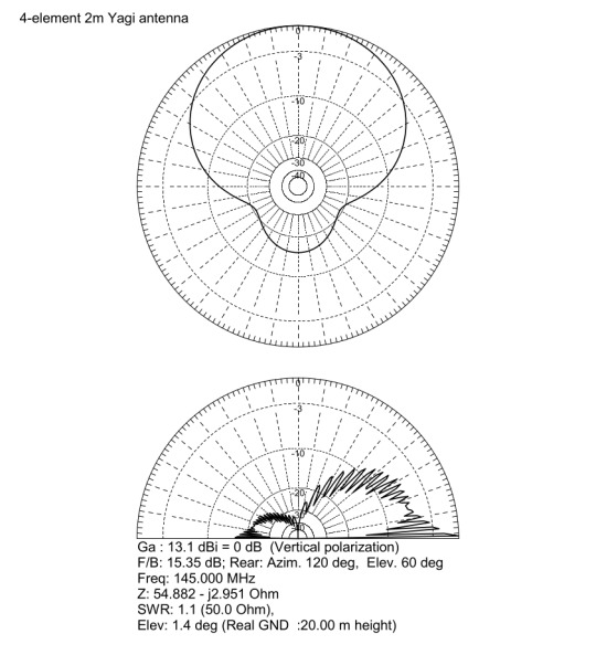
4-Element Yagi antenna for the 2m band
This blog post discusses the engineering design, construction, and performance evaluation of a 4-element Yagi-Uda antenna specifically optimized for the 2-meter amateur radio band, focusing on the frequency range of 144MHz to 145.5MHz. The project was initiated to establish strong and reliable communication with distant VHF repeaters of the RSSL (Radio Society of Sri Lanka), which are located approximately 58km and 96km from my location.

The primary objective was to develop a high-gain, directional antenna with a superior front-to-back ratio. This directionality is essential for maximizing signal capture from the desired repeater while minimizing interference and noise from unwanted directions, ultimately improving the SNR and the quality of the communication link.
VHF communication at these distances typically relies on line-of-sight propagation, making antenna gain a critical factor in overcoming path loss and achieving reliable signal levels.

The antenna design was carried out using MMANA-GAL, a well-known and validated software suite based on the Method of Moments (MoM) for antenna analysis. While MoM simulations require significant computational resources, they deliver accurate predictions of antenna performance. This is achieved by breaking down the antenna structure into small segments and solving Maxwell's equations to determine the current distribution. This approach enables precise modeling of antenna impedance, radiation patterns, gain, and front-to-back ratio.
Key design parameters were iteratively optimized within MMANA-GAL to achieve the desired performance:
Target Frequency Band: 144MHz - 145.5MHz, encompassing the primary 2m amateur band frequencies.
Characteristic Impedance: 50Ω, to ensure impedance matching with standard RG-58 coaxial transmission line and transceiver equipment, minimizing reflected power and maximizing power transfer to the antenna.
Front-to-Back Ratio Optimization: Aiming for a high front-to-back ratio to minimize reception from the rear hemisphere, reducing interference and improving signal clarity, especially in noisy RF environments.
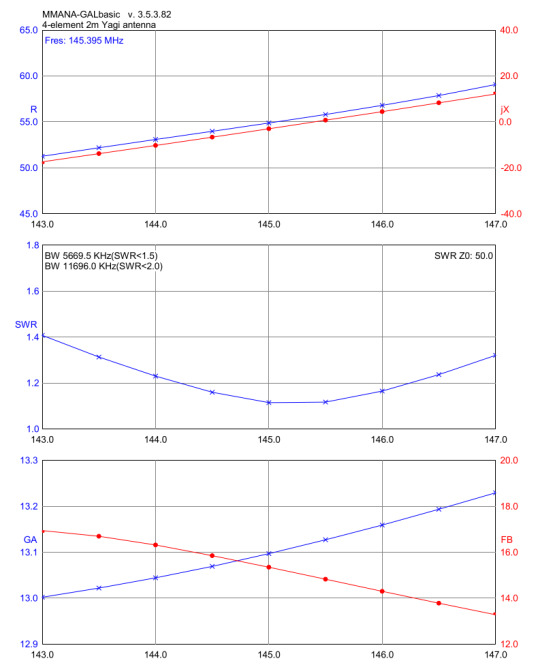
SWR Minimization: Achieving a VSWR as close to 1:1 as possible across the target frequency band. Low VSWR indicates efficient impedance matching and minimal power reflection back to the transmitter.
The simulation process involved adjusting the lengths of the elements and the spacing between them for the reflector, driven element, and directors of the Yagi antenna. This antenna operates on the principles of constructive and destructive interference of electromagnetic waves. The reflector, positioned behind the driven element, reflects waves forward, while the directors, located in front of the driven element, help to focus the radiated energy toward the main lobe. This arrangement increases both the forward gain and directivity of the antenna.

The optimized design, after multiple simulation iterations in MMANA-GAL, predicted the following performance metrics:
Simulated Gain: 13.1dBi. This represents a significant gain increase over a dipole antenna (approximately 2.15dBi) and translates to a substantial improvement in signal strength.
Simulated Front-to-Back Ratio: 15.35dB. This indicates that the power radiated in the forward direction is over 15dB stronger than in the backward direction, providing good directivity and rejection of rearward signals.
Simulated Input Impedance: Close to 50Ω across the 144MHz - 145.5 MHz band, ensuring a good match to standard 50Ω transmission lines.
The construction of the antenna focused on durability, lightweight design, weather resistance, and good electrical conductivity, all while keeping costs reasonable. We used 10mm diameter aluminum alloy tubes sourced from Lanka Aluminum. This diameter was selected because it is commonly available at many aluminum stores.
For the boom, we use a rigid 19.05mm (3/4 inch) square aluminum box bar, also sourced from Lanka Aluminum. This material is made from a similar aluminum alloy to ensure structural integrity and to serve as a common ground plane for the parasitic elements. The square profile enhances torsional stiffness compared to a round boom.
To effectively secure the components, we use 10mm ABS element holders. These holders are commonly utilized here to construct VHF/UHF TV antennas. Both the plastic holders and 10mm end caps are sourced from Kumarasinghe Radio.

The Polychrome junction box, measuring 85×85×50 mm and designed for outdoor use, is waterproof with an IP55 rating. This rating indicates that the box provides protection against dust ingress (although some dust may enter, it won’t cause harm) and shields against water jets from any direction. This makes it an essential choice for long-term outdoor deployment, ensuring the critical dipole feedpoint remains protected.
We used corrosion-resistant M3 stainless steel nuts, bolts, and washers to secure all elements and the IP box.
Precise assembly is crucial for achieving the intended performance of a Yagi antenna. All elements, except for the driven dipole, were directly and electrically bonded to the aluminum boom. This is a standard practice for Yagi antennas, as it utilizes the boom as a common ground, simplifying construction. Electrical connections were established using M3 stainless steel bolts that passed through pre-drilled holes in the aluminum tubes and boom, ensuring reliable electrical contact. The element holders provided mechanical support and maintained precise spacing between the elements, as well as a 90° angle with the boom, in accordance with the design specifications from MMANA-GAL.

The IP55 box containing the dipole was securely mounted to the underside of the aluminum boom using M3 stainless steel fasteners. To ensure consistent height with other elements, we used a strip of 10mm acrylic sheet.
Antenna VSWR and input impedance were measured across the frequency range of 144MHz - 145.5MHz using a VNA. The measured SWR of 1.1 at 145.025MHz confirms excellent impedance matching at the desired operating frequency. A Smith chart, generated by the VNA, visually represented the antenna's impedance characteristics throughout the band. It demonstrated that the impedance remained close to the target of 50Ω, indicating a broadband match across the intended operating frequencies.

The antenna was deployed at the designated operating location and oriented towards the target RSSL VHF repeaters. A subjective performance evaluation was conducted by attempting communication with the repeaters at distances of 58km (Yatiyanthota) and 96km (Piduruthalagala).
Reports from repeater users consistently indicated an S9+ signal strength, showing a significant improvement in reception when compared to a baseline mobile whip antenna.
You can find the complete design of this antenna, including all dimensions, in the PDF linked here. The Fusion 360 design file for the antenna is also available here. Additionally, the MMANA-GAL design file (in .mma format) can be downloaded from this link.
0 notes
Text
This FS1000A 433mHz Tx & Rx RF Module is a Compact, Economic and easy to use wireless RF module with both transmitter and receiver. The module operates at 433MHz and could communicate upto a range of 100 meters with proper antenna design. Practically with normal antenna it could cover distance of 20-50 meters. It can transmit at a speed of 1Kbps to 10Kbps and is easy to use with microcontrollers like Arduino, PIC, AVR etc..
5 notes
·
View notes