#vacuum tube
Text
AM-Detection -the not easy way
Sometimes quite simple things can be a real nightmare if you take a closer look. One of those is AM detection. Your worst enemies are distortion and fading (the latter results in the first). The AM-Detector is only one little part in a receiver, exactly that kind of part usually no one thinks about. "It works, so what should be wrong with?" -a lot and sometimes there's more wrong than right.
A good part of that distinctive AM-Sound we all know is because of the Detector, even under the best conditions. If you're listen to shortwave or the broadcast band during the night then you also have to cope with Fading. Shouldn't be that problem, the automatic gain control takes care of that, right? Ehmmm... Yes. Sometimes. Why the sound gets so distorted when the signal goes down? Just because it's very often 'Selective Fading' and not just Fading -and your Detector doesn't like it.
Really good AM-Reception has a lot in common with High-End-Audio: if it shall work well EVERYTHING has to be well. So let's just talk a bit about Detectors...
Basically the Detector just splits the Audio Signal from the received and amplified Signal. Sounds easy and in fact it is -up to some degree. If you want more than this things getting complicated -really complicated. In at least 999 out of 1000 AM-Receivers for the Detector a small circuitry called 'Envelope Detector' is used, it's just a small Diode (Tube or Semiconductor), a few Resistors and small Capacitors. So, from the view of the Development Engineer: just put half a dozen cheap Components together and Bob's your Uncle. To tell the Truth: compared to the expense that thingy works surprisingly well. Because of this it's the 'Gold Standart' for this task since at least the mid 30s. But as good as it is, it absolutely has it's Limitations. Up to about 15...30% Distortion at a 100% Modulation Level is one, the inability to detect a signal with different sidebands (>selective Fading!) properly another.
To overcome these Limitations a thing named 'Synchronous Detector' was developed many Decades ago. This kind of Circuit has many advantages over the Envelope Detector, but to make one the complexity and the component count of those is just hilarious compared to the Envelope Detector. If only the result counts and nothing else: that's the way to go. We'll talking later how this exactly works, but before this you have to know that in a receiver with a Synchronous Detector also an Envelope Detector is needed: just for tuning in. So first we'll have a closer look how we can get the most ideal Envelope Detector.
Basically it's quite simple: want to have low overall Distortion? Feed it with at least 'a few' volts RF at it's input for having a high ratio between the input voltage and the 'forward voltage' of the Diode. Want low Distortion at low modulation levels? Use a Diode with low Impedance and a load Resistor with a value as low as possible. Want low Distortion at high modulation levels? Just make the input Impedance of the following Stage as high as possible for having the highest possible Ratio between the Resistance of the Load Resistor and the input Impedance of the following Stage.
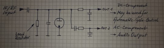
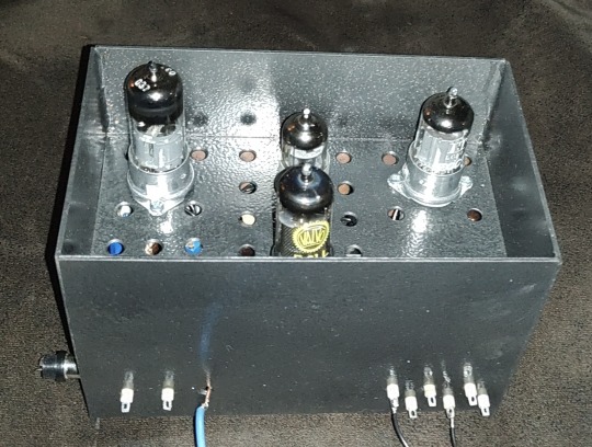
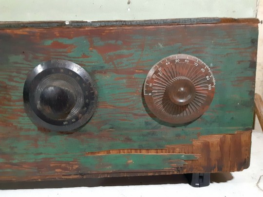
The Receiver i wanted to use (R+S EK07) has an IF output, meant for exactly such things, the IF Level there's about 250mVpp @ 300kHz. So having everything above in mind -and just adding a 700mVpp IF output for the Synchronous Detector and an additional AGC-Circuitry, then we're coming to this:

The EK07 is a fully tube equipped receiver, so i also want to use tubes as far as possible and -like in the EK07- in a way which guarantees 10k's of Service hours. If at one point a Semiconductor may perform muuuch better -ok, so then. First of all i want high performance. So what tubes may perform optimal here?
For the first IF-Amp (IF1) not much is needed, the Gain is only about 3, the output voltage low and besides that it has to be an remote-controlled type. Selectivity isn't needed or desired, so no IF-Can, only a Broad-Band setup. Nearly every IF-Tube with a Transconductance of at least about 3000mhos (3mA/V) would do that job. To have better performance i took the EF805s, which is a Special Quality Version of the EF85 -or 6BY7.
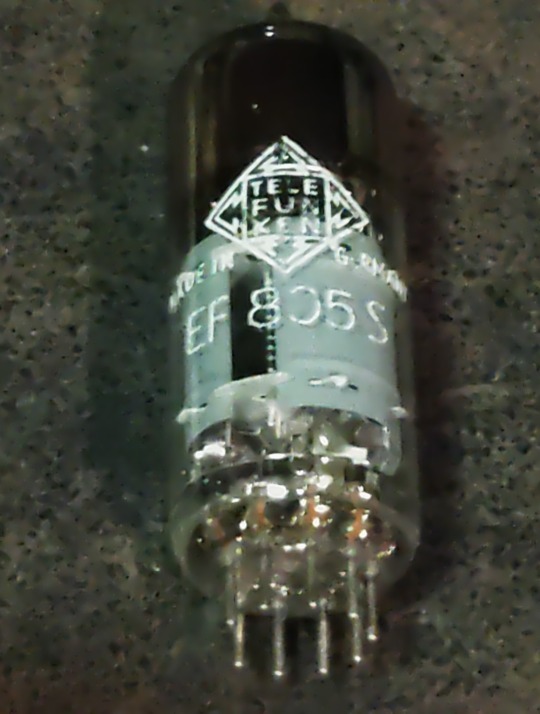
Transconductance is about twice what's needed, so we'll have Gain to spare, anyway, it's getting controlled with the AGC so it will work with less current which adds greatly to the service life. So no problems here.
For the second IF-Amp (IF2), things aren't exactly that easy. First: the output for the Synchronous Detector is placed between both Amps and has to deliver a constant voltage, so for the 2nd IF we need an Amplifier with an fixed Gain. A STABLE fixed Gain over long time periods. Further we want to have a relatively high and undistorted output voltage which calls for quite a bit of gain. Wait: there was also that thing with the low-value Load Resistor in the detector itself -so we also need a quite reasonable amount of output power from this stage. In Addition we want to have a stable gain for a time as long as possible. A IF-Tube like the EF805s could also handle this, but then we have to 'beat the crap' out of this thing. Not a good start for a long and stable service life, also not with Special Quality Tubes.
Because of all that my choice was a kinda 'special'-Special-Quality type: the E81L.

The datasheet calls this a 'Long range, Special Quality Tube for the use in Telephone Equipment'. Telephone Equipment? Like an answering machine?? Nope, by far not. Back in these days telephone companies needed to have Amplifiers for pushing the calls through loooong cables for long range service. But: this was all multiplex service, so they pushed dozens and dozens of calls simultaneously through one pair of wires or a Coax. The same way like for cable TV. THIS was these bulbs were meant for. For this task every company employed tens of thousands of such tubes 24/7/365. If a single one failed -most likely somewhere in nowhere of course- they had a problem. So they absolutely had to last.
These little bulbs are designed for about 4.5W plate dissipation at 20mA, the Transconductance is 11000mhos (11mA/V)-so it's about twice an usual IF Tube in every respect. So that's exactly what's needed here: a tube especially designed to last, quite powerful, so we can drive it with comfortable low settings, enhancing service life and stability much further.
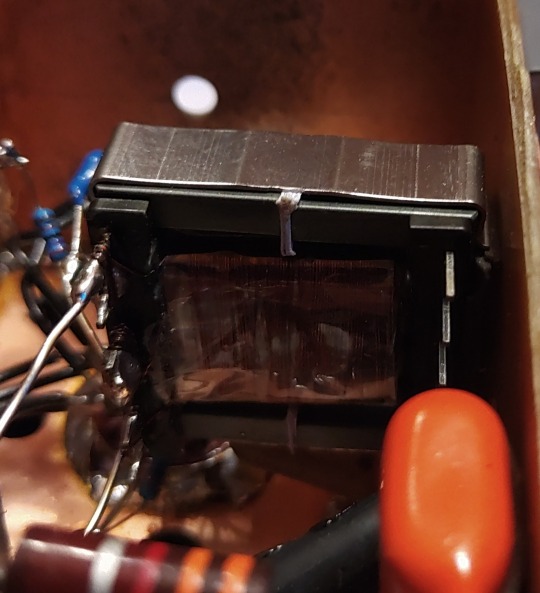
Because we need some amount of power the usual Broad-Band Amplifier arrangement (still: selectivity is not wanted or desired) with just a plate Resistor isn't good here, a suitable inductor works way better here. This has the further advantage that we can build it with a Tab like an Autotransformer -we don't need that much voltage it could deliver with that inductor by far, so this adds further to a good SNR and lower output Impedance. 300kHz trough a transformer? Yep, no problem. Just use the right core. Here it's not a laminated iron core but a ferrite one instead. Cause it's a single-A Amplifier of course we must add an air-gap, preventing saturation.
In a penthode stage the gain depends nearly exclusively on the Transconductance of the tube used, have to much just cut it down. The E81L has a quite high transconductance, about 3 times more than needed -and in the same order than big output tubes like the 6550, EL34 or 6CA7. For cutting that down to the desired level just put a Resistor or Pot in series to the bypass cap of the cathode Resistor. This acts as an series feedback so it also enhances linearity and long time stability greatly. Yap, i thought quite a while about which tube i should use here.
So after all Amplification is done now, we need a Diode for the Envelope Detector. Back in the Octal-Days this was the 6H6 / EB34, later in the Miniature-Days the 6AL5 / EAA91, both with two separate diodes in one bottle (or Can for the 6H6). These were not A DIODE, these were THE DIODE, so there's not much to choose from. Both are kinda close to each other, but are these ideal for what we want? They both can handle a reverse voltage of several hundreds of volts, so waaaay more than we need here. Both having a Plate Resistance of 600-something Ohms per System which is quite low -could be lower, even with both Systems in parallel. Of course these would be work well, no doubt about. But still.... Hey, this should be High-end so we're whining here at a very high level!
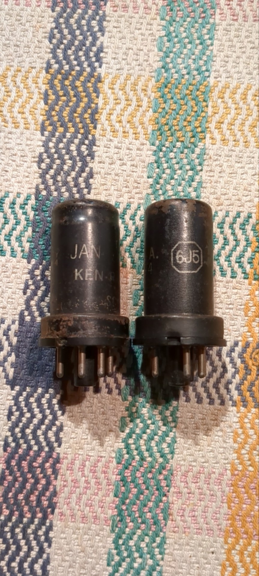
Basically we can use EVERY TUBE as a diode: just take the control grid as Anode, the Cathode as what it is and everything else as Shielding. We don't need hundreds of Volts reverse Voltage, nor high current, so also no big Cathode. We only want to have an internal Resistance as low as possible, so a close spacing between the Grid and the Cathode. This calls for a small Tube with a high Gm (or Transconductance) -like the 6AK5 / EF95. Can it handle the reverse voltage we need? Datasheet says 50V, so at least twice of what's needed. So just take one, put some current trough and take the voltage drop. Result: 210 ohms -way less than that what one of the double-diodes would provide, even with both Systems in parallel. Fits very well!

This is the soviet-military version of the 6AK5W / E95F. Special Quality. See these 'trenches' in the bulb? And the microscopic rivets holding the Plate together? The Soviets literally ruggedized the heck out of this tube! Why? Just because they used it widely in their Fighter Planes, ICBM's, Tanks and so on. Doubts about the soviet built quality? Hey, they wanted to win WWIII with them -so: nope. If you ever saw a ruggedized tube: this it is.
After the Detector itself is done, we come to last part of our little contraption: the buffer Amplifier. At the output of the Detector we have the AF as well with the overlayed AGC-Voltage and we want to have an input Impedance as high as possible for the Buffer Amp. Voltage Gain isn't needed -we have plenty of both from the Detector- so we just can use a Cathode Follower for the buffer. Ideally the Buffer should handle both voltages simultaneously, but then the output will be negative with respect to Ground. How to....? Simple: just put that thing between a positive and a negative supply rail. Then the output can swing freely between every positive or negative Potential as desired. Further: we don't need a Grid Resistor! The Grid just follows any voltage swing of the Detector, this also adds to a high input Impedance.
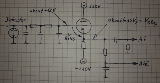
This Circuit will provide us a very high input Impedance, but this is High-End! So: what tube will be the best for? Because of the lack of any Grid Resistor the input Impedance depends now largely on the contact potential of the grid. So we want a tube with low contact potential which calls for a tube with a low Transconductance. Further we want a tube which needs only a low bias voltage for it's Grid, 'cause we'll loose any bias-volt in our AGC-Output voltage. This calls for a tube with an high Gain. Low contact potential and low Transconductance? High Gain?? That's the 12AX7 / ECC83! Ok, it's of course a double Triode, but we still can use the second system for something else -like for the Line-Output Amp. In that Stage there's not much needed so it also will perform well enough there -we're still talking about AM!
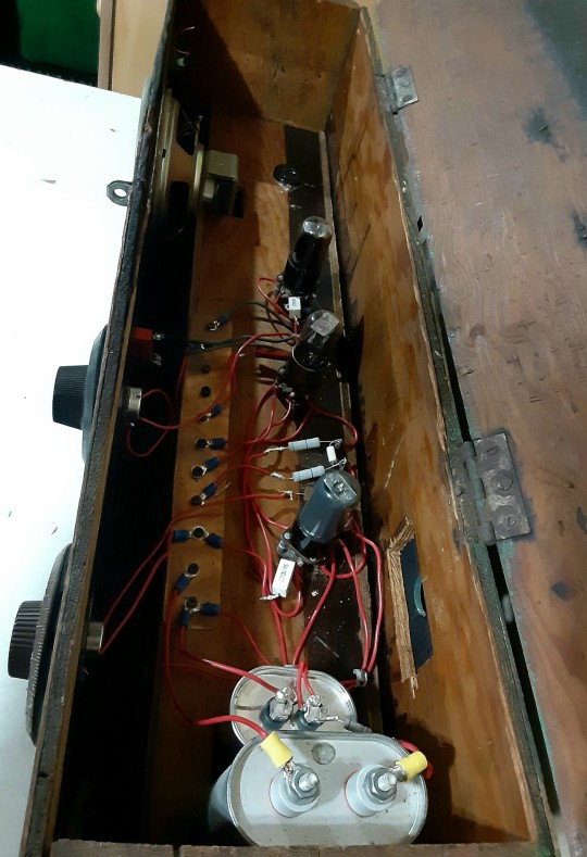
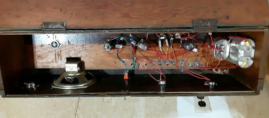
So let's put everything neatly together, adding adequate shielding and so on -and we get this:
So now it's time to have a closer look we did everything right. Just put a 300kHz-Carrier in, 100% modulated with a triangle-signal. We should get a perfect Triangle at the AF-Output -if physics are with us. Due to the Triangle Signal any Distortion can easily be spotted on the Scope.
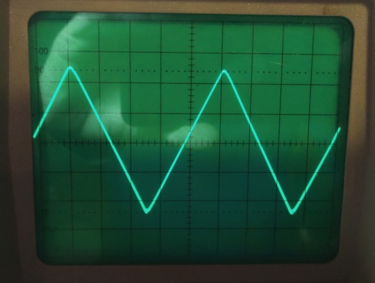
Looks promising! But somehow... Is the beam defocused? Let's take a very close look:

No, it's not. Those are just the very small remnants of the Carrier, so we actually have a look how the Detector works on a nearly 'microscopic' Level. I could take a measurement how much distortion we have left, but the Flanks of the Triangle are perfectly straight, so the Distortion will be really small -like 1% or so worst case. At least for the moment it's not worth the Effort. Compared to the usual 15...30% Distortion at a 100%-Modulation level this works really well, there's no doubt about.
So finally: we wanted to have a Envelope-Detector as good as possible and here we are. Ok, tbh it's better than needed, cause finally the REAL Detector will be a synchronous one. So why i took this that far? Easy: because of mental peace. Now i never have to think about if that part of the whole final thing could work better. As i said before: it's High-End.
Will update you if the next module is ready. But i fear this here was just the more easy part of the whole thing. From now on things may get a bit more tricky...
2 notes
·
View notes
Photo


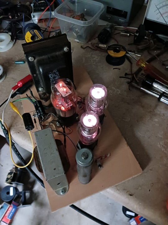

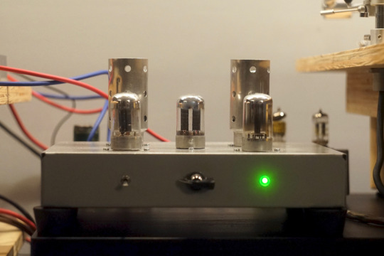
Put the finishing touches on my vacuum tube power supply yesterday.
This is the first time I’ve designed any tube gear from scratch, so I was really relieved when it didn’t blow up. :D
This supply uses a type 83V rectifier and 2 0D3 voltage regulator tubes, outputting around 300V at 40mA. I’m going to use this supply to power a vacuum tube preamp. I know I’ve built one of those already, but the one I built is a line-level preamp. I’d like to build a phono preamp so I can experiment with a pure analog signal from my turntable, through the preamp, into my vacuum tube amplifier and out to my speakers.
The 0D3 tubes aren’t really necessary for this application, but I wanted to use them because they glow a cool purple-pink color when activated. Like other builds I’ve done it’s part function, part aesthetics.
Next step is to order some of the parts (mostly electrolytic capacitors) I need for the audio section, then layout a chassis and start building!
Stay tuned for other things that glow.
38 notes
·
View notes
Text
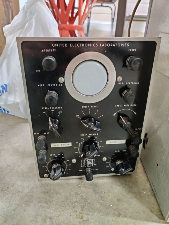
A kit oscilloscope! Given out to institutions such as aircraft mechanic training centers, with a few replacement vacuum tubes maybe I can get it working again!
35 notes
·
View notes
Photo
De-noising the JEL Loctal Phono Preamp
3 notes
·
View notes
Text
Retro apocalyptic tri-tube amplifier
Created a few years ago, now being reworked for bluetooth; maybe more.
2 notes
·
View notes
Text
Arkham Sound Oracle: Vintage-Inspired Tube Pre-Amplifier
The Arkham Sound Oracle has been updated and refined. This single-channel vacuum tube pre-amplifier draws its inspiration from the iconic Portaflex Bass amps of the 1960s. Designed with a focus on delivering top-notch performance, the Oracle offers a range of features that will elevate your guitar-playing experience.
Arkham Sound Oracle
The Arkham Sound Oracle is equipped with a buffered 1/4″…

View On WordPress
#&039;60s#12AX7#1960s#Ampeg#Arkham Sound#Arkham Sound Oracle#DAW#DI#Ground Lift#Instagram#James Tonestack#live#Maine#Oracle#Orange#pedal#Portaflex Bass#Pre-amplifier#preamp#Recording#Sixties#stompbox#tube#USA#vacuum tube#video#vintage tube#XLR#YouTube
0 notes
Text

The global hyperloop technology market has garnered significant attention in recent years, promising a revolution in transportation. Read More: https://cmi-reports.blogspot.com/2023/06/exploring-global-hyperloop-technology.html
#coherent market insights#Smart Technologies Industry#Hyperloop Technology Market#Transportation#High-speed#Infrastructure#Magnetic levitation#Vacuum tube#Propulsion system
0 notes
Text
halo effect
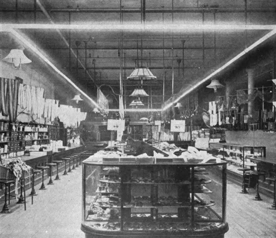
The Moore Tube Light, 1904.
This consisted of a tube about 1¾ inches in diameter and having a length up to 200 feet, in which air at about one thousandth part of atmospheric pressure was made to glow by a very high voltage alternating current.
link
“The first installation of this form of lamp was in a hardware store in Newark, N.J.”
in section Incandescent Light Developments, 1894-1904
Henry Schroeder, History of Electric Light, Smithsonian Miscellaneous Collections 76:2 (August 15, 1923) : link (hathitrust)
—
Henry Schroder (1879-1952)
bio (by Edward J. Covington) and portrait at lamptech.co.uk : link (accessed 20230426)
lamptech : Museum of Electric Light Technology : link
0 notes
Photo
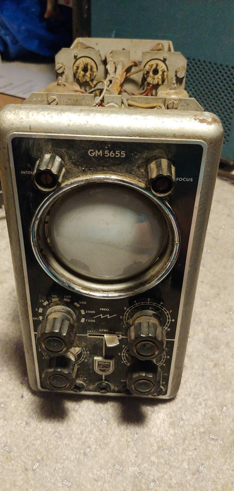

I got this old philips gm 5655 vacuum tube osciloscope from a person on facebook marketplace the other day and I fell like sharing a bit of the restorating process! :)
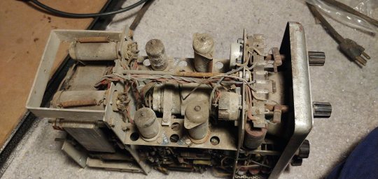
here it is starting off really dirty and nasty. it seems to me like it’s been in storage in someones barn/shed for the last 50 odd years. it’s case has a lot of vent holes cuz it is small and power hungery with no fans to be found and this means that dust and detritus has happily fallen into it along with a couple bugs who have taken home inside of it.
I plugged it in and.... nothing :/
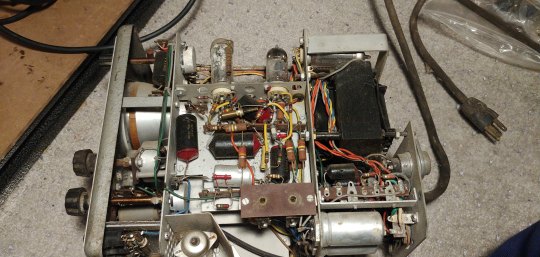
so the first step in restoring it is cleaning it enough to not want to gag while working on it.
1 note
·
View note
Text
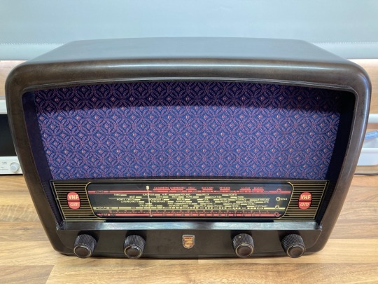
1956 Philips 353A Bakelite Vacuum Tube Radio Repair & Restoration
1956 Philips 353A Bakelite Vacuum Tube Radio Repair & Restoration
View On WordPress
0 notes
Text
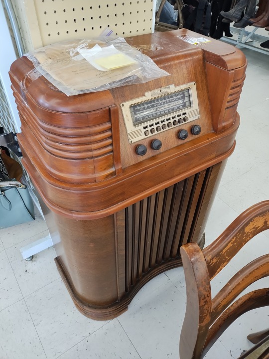
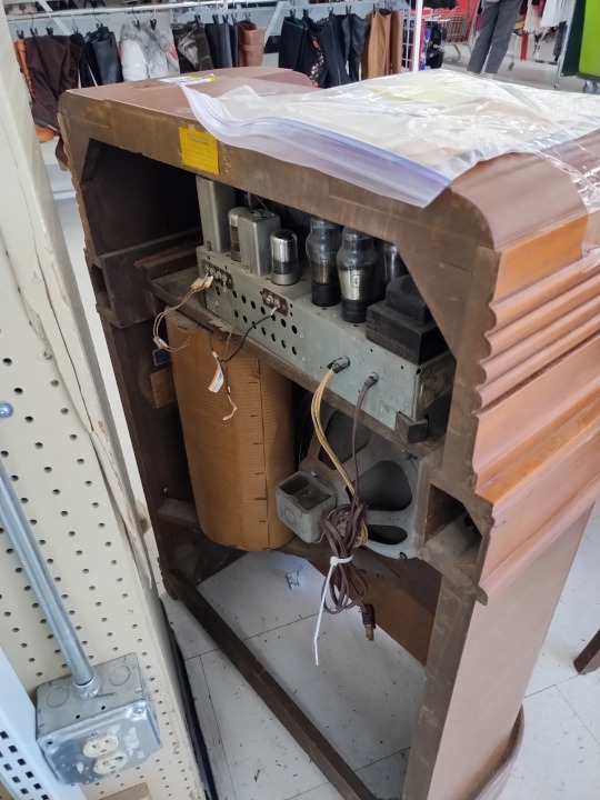
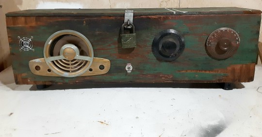
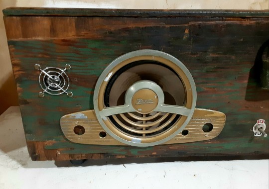
Philco 40-180 seven-tube AM radio from 1940, being sold for parts but I'm sure someone could figure out which vacuum tube to change to get it back into gear.

213 notes
·
View notes
Text
How a Computer Works - Part 1 (Components)
I am about to teach you on a real fundamental, connecting up electronic components level, how a computer actually works. Before I get into the meat of this though (you can just skip down below the fold if you don't care), here's the reasons I'm sitting doing so in this format:
Like a decade or two ago, companies Facebook pushed this whole "pivot to video" idea on the whole internet with some completely faked data, convincing everyone that everything had to be a video, and we need to start pushing back against that. Especially for stuff like complex explanations of things or instructions, it's much more efficient to just explain things clearly in text, maybe with some visual aids, so people can easily search, scan, and skip around between sections. It's also a hell of a lot easier to host things long term, and you can even print out a text based explainer and not need a computer to read it, keep it on a desk, highlight it, etc.
People are so clueless about how computers actually work that they start really thinking like it's all magical. Even programmers. Aside from how proper knowledge lets you get more out of them, this leads to people spouting off total nonsense about "teaching sand to think" or "everything is just 1s and 0s" or "this 'AI' a con artist who was trying to sell me NFTs a month ago probably really is an amazing creative thinking machine that can do everything he says!"
We used to have this cultural value going where it was expected that if you owned something and used it day to day, you'd have enough basic knowledge of how it worked that if it stopped working you could open it up, see what was wrong, and maybe fix it on your own, or maybe even put one together again from scratch, and that's obviously worth bringing back.
I'm personally working on a totally bonkers DIY project and I'd like to hype up like-minded people for when it gets farther along.
So all that said, have a standard reminder that I am completely reliant on Patreon donations to survive, keep updating this blog, and ideally start getting some PCBs and chips and a nice oscilloscope to get that mystery project off the ground.
Electricity probably doesn't work like how you were taught (and my explanation shouldn't be trusted too far either).
I remember, growing up, hearing all sorts of things about electricity having this sort of magical ability to always find the shortest possible path to where it needs to get, flowing like water, and a bunch of other things that are kind of useful for explaining how a Faraday cage or a lightning rod works, and not conflicting with how simple electronics will have a battery and then a single line of wire going through like a switch and a light bulb or whatever back to the other end of the battery.
If you had this idea drilled into your head hard enough, you might end up thinking that if we have a wire hooked to the negative end of a battery stretching off to the east, and another wire stretching off to the east from the positive end, and we bridge between the two in several places with an LED or something soldered to both ends, only the westernmost one is going to light up, because hey, the shortest path is the one that turns off as quickly as possible to connect to the other side, right? Well turns out no, all three are going to light up, because that "shortest path" thing is a total misunderstanding.
Here's how it actually works, roughly. If you took basic high school chemistry, you learned about how the periodic table is set up, right? A given atom, normally, has whatever number of protons in the core, and the same number of electrons, whipping all over around it, being attracted to those protons but repelled by each other, and there's particular counts of electrons which are super chill with that arrangement so we put those elements in the same column as each other, and then as you count up from those, you get the elements between those either have some electrons that don't fit all tight packed in the tight orbit and just kinda hang out all wide and lonely and "want to" buddy up with another atom that has more room, up to the half full column that can kinda go either way, then as we approach the next happy number they "want to" have a little more company to get right to that cozy tight packed number, and when you have "extra" electrons and "missing" electrons other atoms kinda cozy up and share so they hit those good noble gas counts.
I'm sure real experts want to scream at me for both that and this, but this is basically how electricity works. You have a big pile of something at the "positive" end that's "missing electrons" (for the above reason or maybe actually ionized so they really aren't there), and a "negative" end that's got spares. Then you make wires out of stuff from those middle of the road elements that have awkward electron counts and don't mind buddying up (and also high melting points and some other handy qualities) and you hook those in there. And the electron clouds on all the atoms in the wire get kinda pulled towards the positive side because there's more room over there, but if they full on leave their nucleus needs more electron pals, so yeah neighbors get pulled over, and the whole wire connected to the positive bit ends up with a positive charge to it, and the whole wire on the negative bit is negatively charged, and so yeah, anywhere you bridge the gap between the two, the electrons are pretty stoked about balancing out these two big awkward compromises and they'll start conga lining over to balance things out, and while they're at it they'll light up lights or shake speakers or spin motors or activate electromagnets or whatever other rad things you've worked out how to make happen with a live electric current.
Insulators, Resistors, Waves, and Capacitors
Oh and we typically surround these wires made of things that are super happy about sharing electrons around with materials that are very much "I'm good, thanks," but this isn't an all or nothing system and there's stuff you can connect between the positive and negative ends of things that still pass the current along, but only so much so fast. We use those to make resistors, and those are handy because sometimes you don't want to put all the juice you have through something because it would damage it, and having a resistor anywhere along a path you're putting current through puts a cap on that flow, and also sometimes you might want a wire connected to positive or negative with a really strong resistor so it'll have SOME sort of default charge, but if we get a free(r) flowing connection attached to that wire somewhere else that opens sometimes, screw that little trickle going one way, we're leaning everyone the other way for now.
The other thing with electricity is is that the flow here isn't a basic yes/no thing. How enthusiastically those electrons are getting pulled depends on the difference in charge at the positive and negative ends, and also if you're running super long wires then even if they conduct real good, having all that space to spread along is going to kinda slow things to a trickle, AND the whole thing is kinda going to have some inherent bounciness to it both because we're dealing with electrons whipping and spinning all over and because, since it's a property that's actually useful for a lot of things we do with electricity, the power coming out of the wall has this intentional wobbly nature because we've actually got this ridiculous spinny thing going on that's constantly flip flopping which prong of the socket is positive and which is negative and point is we get these sine waves of strength by default, and they kinda flop over if we're going really far.
Of course there's also a lot of times when you really want to not have your current flow flickering on and off all the time, but hey fortunately one of the first neat little electronic components we ever worked out are capacitors... and look, I'm going to be straight with you. I don't really get capacitors, but the basic idea is you've got two wires that go to big wide plates, and between those you have something that doesn't conduct the electricity normally, but they're so close the electromagnetic fields are like vibing, and then if you disconnect them from the flow they were almost conducting and/or they get charged to their limit, they just can't deal with being so charged up and they'll bridge their own gap and let it out. So basically you give them electricity to hold onto for a bit then pass along, and various sizes of them are super handy if you want to have a delay between throwing a switch and having things start doing their thing, or keeping stuff going after you break a connection, or you make a little branching path where one branch connects all regular and the other goes through a capacitor, and the electricity which is coming in in little pulses effectively comes out as a relatively steady stream because every time it'd cut out the capacity lets its charge go.
We don't just have switches, we have potentiometers.
OK, so... all of the above is just sort of about having a current and maybe worrying about how strong it is, but other than explaining how you can just kinda have main power rails running all over, and just hook stuff across them all willy-nilly rather than being forced to put everything in one big line, but still, all you can do with that is turn the whole thing on and off by breaking the circuit. Incidentally, switches, buttons, keys, and anything else you use to control the behavior of any electronic device really are just physically touching loose wires together or pulling them apart... well wait no, not all, this is a good bit to know.
None of this is actually pass/fail, really, there's wave amplitudes and how big a difference we have between the all. So when you have like, a volume knob, that's a potentiometer, which is a simple little thing where you've got your wire, it's going through a resistor, and then we have another wire we're scraping back and forth along the resistor, using a knob, usually, and the idea is the current only has to go through X percent of the resistor to get to the wire you're moving, which proportionately reduces the resistance. So you have like a 20 volt current, you've got a resistor that'll drop that down to 5 or so, but then you move this other wire down along and you've got this whole dynamic range and you can fine tune it to 15 or 10 or whatever coming down that wire. And what's nice about this again, what's actually coming down the wire is this wobbily wave of current, it's not really just "on" or "off, and as you add resistance, the wobble stays the same, it's just the peaks and valleys get closer to being just flat. Which is great if you're making, say, a knob to control volume, or brightness, or anything you want variable intensity in really.
Hey hey, it's a relay!
Again, a lot of the earliest stuff people did with electronics was really dependent on that analog wobbly waveform angle. Particularly for reproducing sound, and particularly the signals of a telegraph. Those had to travel down wires for absurd distances, and as previously stated, when you do that the signal is going to eventually decay to nothing. But then someone came up with this really basic idea where every so often along those super long wires, you set something up that takes the old signal and uses it to start a new one. They called them relays, because you know, it's like a relay race.
If you know how an electromagnet works (something about the field generated when you coil a bunch of copper wire around an iron core and run an electric current through it), a relay is super simple. You've got an electromagnet in the first circuit you're running, presumably right by where it's going to hit the big charged endpoint, and that magnetically pulls a tab of metal that's acting as a switch on a new circuit. As long as you've got enough juice left to activate the magnet, you slam that switch and voom you've got all the voltage you can generate on the new line.
Relays don't get used too much in other stuff, being unpopular at the time for not being all analog and wobbily (slamming that switch back and forth IS going to be a very binary on or off sorta thing), and they make this loud clacking noise that's actually just super cool to hear in devices that do use them (pinball machines are one of the main surviving use cases I believe) but could be annoying in some cases. What's also neat is that they're a logical AND gate. That is, if you have current flowing into the magnet, AND you have current flowing into the new wire up to the switch, you have it flowing out through the far side of the switch, but if either of those isn't true, nothing happens. Logic gates, to get ahead of myself a bit, are kinda the whole thing with computers, but we still need the rest of them. So for these purposes, relays re only neat if it's the most power and space efficient AND gate you have access to.
Oh and come to think of it, there's no reason we need to have that magnet closing the circuit when it's doing its thing. We could have it closed by default and yank it open by the magnet. Hey, now we're inverting whatever we're getting on the first wire! Neat!
Relay computers clack too loud! Gimme vacuum tubes!
So... let's take a look at the other main thing people used electricity for before coming up with the whole computer thing, our old friend the light bulb! Now I already touched a bit on the whole wacky alternating current thing, and I think this is actually one of the cases that eventually lead to it being adopted so widely, but the earliest light bulbs tended to just use normal direct current, where again, you've got the positive end and the negative end, and we just take a little filament of whatever we have handy that glows when you run enough of a current through it, and we put that in a big glass bulb and pump out all the air we can, because if we don't, the oxygen in there is probably going to change that from glowing a bit to straight up catching on fire and burning immediately.
But, we have a new weird little problem, because of the physics behind that glowing. Making something hot, on a molecular level, is just kinda adding energy to the system so everything jitters around more violently, and if you get something hot enough that it glows, you're getting it all twitchy enough for tinier particles to just fly the hell off it. Specifically photons, that's the light bit, but also hey, remember, electrons are just kinda free moving and whipping all over looking for their naked proton pals... and hey, inside this big glass bulb, we've got that other end of the wire with the more positive charge to it. Why bother wandering up this whole coily filament when we're in a vacuum and there's nothing to get in the way if we just leap straight over that gap? So... they do that, and they're coming in fast and on elliptical approaches and all, so a bunch of electrons overshoot and smack into the glass on the far side, and now one side of every light bulb is getting all gross and burnt from that and turning all brown and we can't have that.
So again, part of the fix is we switched to alternating current so it's at least splitting those wild jumps up to either side, but before that, someone tried to solve this by just... kinda putting a backboard in there. Stick a big metal plate on the end of another wire in the bulb connected to a positive charge, and now OK, all those maverick electrons smack into here and aren't messing up the glass, but also hey, this is a neat little thing. Those electrons are making that hop because they're all hot and bothered. If we're not heating up the plate they're jumping to, and there's no real reason we'd want to, then if we had a negative signal over on that side... nothing would happen. Electrons aren't getting all antsy and jumping back.
So now we have a diode! The name comes because we have two (di-) electrodes (-ode) we care about in the bulb (we're just kind of ignoring the negative one), and it's a one way street for our circuit. That's useful for a lot of stuff, like not having electricity flow backwards through complex systems and mess things up, converting AC to DC (when it flips, current won't flow through the diode so we lop off the bottom of the wave, and hey, we can do that thing with capacitors to release their current during those cutoffs, and if we're clever we can get a pretty steady high).
More electrodes! More electrodes!
So a bit after someone worked out this whole vacuum tube diode thing, someone went hey, what if it was a triode? So, let's stick another electrode in there, and this one just kinda curves around in the middle, just kinda making a grate or a mesh grid, between our hot always flowing filament and that catch plate we're keeping positively charged when it's doing stuff. Well this works in a neat way. If there's a negative charge on it, it's going to be pushing back on those electrons jumping over, and if there's a positive charge on it, it's going to help pull those electrons over (it's all thin, so they're going to shoot right past it, especially if there's way more of a positive charge over on the plate... and here's the super cool part- This is an analog thing. If we have a relatively big negative charge, it's going to repel everything, if it's a relatively big positive, it's going to pull a ton across, if it's right in the middle, it's like it wasn't even in there, and you can have tiny charges for all the gradients in between.
We don't need a huge charge for any of this though, because we're just helping or hindering the big jump from the high voltage stuff, and huh, weren't we doing this whole weak current controlling a strong current thing before with the relay? We were! And this is doing the same thing! Except now we're doing it all analog style, not slapping switch with a magnet, and we can make those wavy currents peak higher or lower and cool, now we can have phone lines boost over long distances too, and make volume knobs, and all that good stuff.
The relay version of this had that cool trick though where you could flip the output. Can we still flip the output? We sure can, we just need some other toys in the mix. See we keep talking about positive charges and negative charges at the ends of our circuits, but these are relative things. I mentioned way back when how you can use resistors to throttle how much of a current we've got, so you can run two wires to that grid in the triode. One connects to a negative charge and the other positive, with resistors on both those lines, and a switch that can break the connection on the positive end. If the positive is disconnected, we've got a negative charge on the grid, since it's all we've got, but if we connect it, and the resistor to the negative end really limits flow, we're positive in the section the grid's in. And over on the side with the collecting plate, we branch off with another resistor setup so the negative charge on that side is normally the only viable connection for a positive, but when we flip the grid to positive, we're jumping across the gap in the vacuum tube, and that's a big open flow so we'll just take those electrons instead of the ones that have to squeeze through a tight resistor to get there.
That explanation is probably a bit hard to follow because I'm over here trying to explain it based on how the electrons are actually getting pulled around. In the world of electronics everyone decided to just pretend the flow is going the other way because it makes stuff easier to follow. So pretend we have magical positrons that go the other way and if they have nothing better to do they go down the path where we have all the fun stuff further down the circuit lighting lights and all that even though it's a tight squeeze through a resistor, because there's a yucky double negative in the triode and that's worse, but we have the switch rigged up to make that a nice positive go signal to the resistance free promised land with a bonus booster to cut across, so we're just gonna go that way when the grid signal's connected.
Oh and you can make other sorts of logic circuits or double up on them in a single tube if you add more grids and such, which we did for a while, but not really relevant these days.
Cool history lesson but I know there's no relays or vacuum tubes in my computer.
Right, so the above things are how we used to make computers, but they were super bulky, and you'd have to deal with how relays are super loud and kinda slow, and vacuum tubes need a big power draw and get hot. What we use instead of either of those these days are transistors. See after spending a good number of years working out all this circuit flow stuff with vacuum tubes we eventually focused on how the real important thing in all of this is how with the right materials you can make a little juncture where current flows between a positive and negative charge if a third wire going in there is also positively charged, but if it's negatively charged we're pulling over. And turns out there is a WAY more efficient way of doing that if you take a chunk of good ol' middle of the electron road silicon, and just kinda lightly paint the side of it with just the tiniest amount of positive leaning and negative leaning elements on the sides.
Really transistors don't require understanding anything new past the large number of topics already covered here, they're just more compact about it. Positive leaning bit, negative leaning bit, wildcard in the middle, like a vacuum tube. Based on the concepts of pulling electrons around from chemistry, like a circuit in general. The control wire in the middle kinda works in just a pass-fail sort of way, like a relay. They're just really nice compared to the older alternatives because they don't make noise or have moving parts to wear down, you don't have to run enough current through them for metal to start glowing and the whole room to heat up, and you can make them small. Absurdly small. Like... need an electron microscope to see them small.
And of course you can also make an inverter super tiny like that, and a diode (while you're at it you can use special materials or phosphors to make them light emitting, go LEDs!) and resistors can get pretty damn small if you just use less of a more resistant material, capacitors I think have a limit to how tiny you can get, practically, but yeah, you now know enough of the basic fundamentals of how computers work to throw some logic gates together. We've covered how a relay, triode, or transistor function as an AND gate. An OR gate is super easy, you just stick diodes on two wires so you don't have messy backflow then connect them together and lead off there. If you can get your head around wiring up an inverter (AKA NOT), hey, stick one after an AND to get a NAND, or an OR to get a NOR. You can work out XOR and XNOR from there right? Just build 4 NANDs, pass input A into gates 1 and 2, B into 2 and 3, 2's output into 1 and 3, 1 and 3's output into 4 for a XOR, use NORs instead for a XNOR. That's all of them right? So now just build a ton of those and arrange them into a computer. It's all logic and math from there.
Oh right. It's... an absurd amount of logic and math, and I can only fit so many words in a blog post. So we'll have to go all...
CONTINUED IN PART 2!
Meanwhile, again, if you can spare some cash I'd really appreciate it.
489 notes
·
View notes
Text

(http://yoshimoto.a.la9.jp/Njta/Njtalogo.htm)
日本駄球協会
National Junk Tube Association
National Junk Tube Society
2 notes
·
View notes
Text
Another oscilloscope score. This one has since been moved to a better home
32 notes
·
View notes
Text
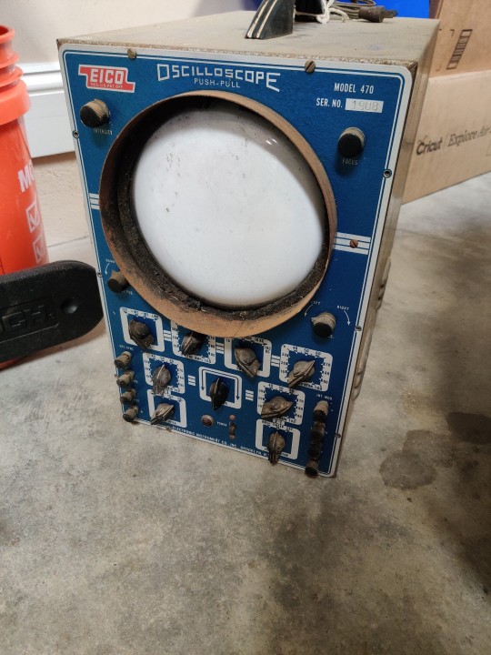
A "String Theory Time Machine Calculator" at the Forest Wood Antique Mall in Dallas, Texas. Working condition (allegedly).

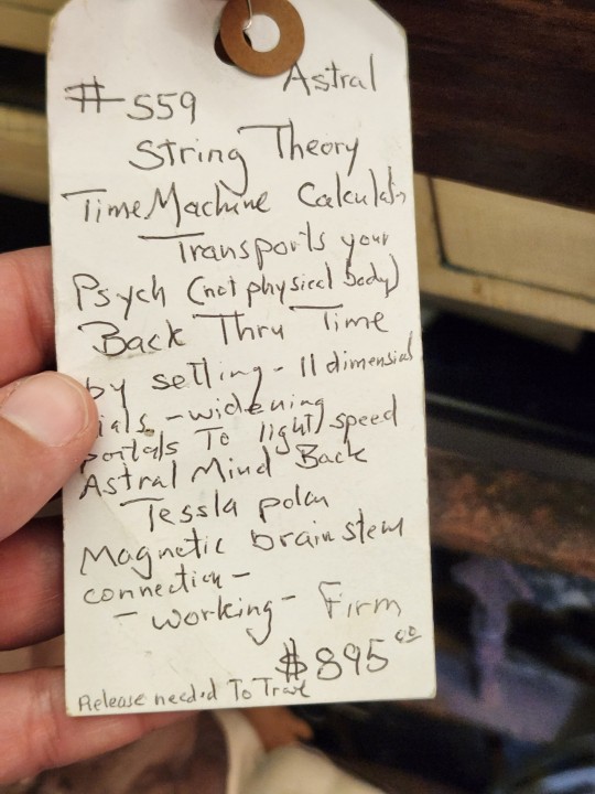
#thrifting#shiftythrifting#submission#bunted skalamarang#time machine#objects#the flag is a nice touch#vacuum tube tester
1K notes
·
View notes
Last Seen Blogs

viscus-0
Мяso

midnight9977
Midnight

starryyskies
I draw sometimes

wildthunder312
Keep Moving Forward

boy-create
Untitled