#ArduinoJSON
Explore tagged Tumblr posts
Visit Tumblr Blog
Explore Tumblr blogs with no restrictions, modern design and the best experience.
Last Seen Tumblr Blogs


Fun Fact
The “We are the 99%” Tumblr blog became the slogan for the Occupy Wall Street movement.
Text
Универсальный бокс для дрона
Предисловие
Данная статья это рассказ об отдельной части моего проекта по созданию системы доставки дронами. Система совсем в ранней стадии разработки. Но в принципе эта часть готова и если кому интересно может пользоваться в своих проектов. Если будет заинтересованность могу продолжить публиковать чертежи, схемы и программный код.
Введение
📦 открывать и закрывать отсек для груза;
🔋 открывать и закрывать отсек для сменного аккумулятора;
📡 передавать телеметрию о состоянии устройства;
✅ принимать команды через WebSocket-сервер.
Аппаратная часть
Устройство построено на контроллере ESP8266 (например, ESP-01 или NodeMCU) и включает в себя:
2 сервопривода: Servo1 — управление крышкой грузового отсека. Servo2 — управление крышкой отсека аккумулятора.
2 концевых переключателя: Button1 — наличие груза в боксе. Button2 — наличие аккумулятора.
Светодиод: используется для индикации состояния соединения.
Сеть и связь
Контроллер подключается к заданной Wi-Fi-сети и устанавливает соединение с WebSocket-сервером. Это позволяет ��ператору дрона или логистической системе управлять боксом в режиме реального времени.
Состояния подключения визуализируются через встроенный светодиод:
✴️ Быстро мигает — нет подключения к Wi-Fi.
⏳ Медленно мигает — Wi-Fi подключен, WebSocket нет.
✅ Постоянно горит — соединение WebSocket установлено.
Принцип работы
После включения устройство:
Подключается к Wi-Fi.
Периодически пытается установить WebSocket-соединение.
После подключения отправляет данные об устройстве (идентификатор и пароль).
Ожидает команды от сервера и реагирует на них.
Обработка команд
Поддерживаются следующие команды:
"servo1" — установить угол открытия грузового отсека.
"servo2" — установить угол открытия аккумуляторного отсека.
"reboot" — перезагрузка устройства.
Телеметрия
Устройство автоматически отправляет телеметрию по команде "PING":
Статус "работает",
Углы обоих сервоприводов,
Состояние обоих концевиков ("pressed" или "released").
Кнопки (концевики)
Концевики подключены с использованием программного класса Button. Система отслеживает их состояния и отправляет обновления при нажатии или по таймеру (раз в секунду), если WebSocket-соединение активно.
Программная архитектура
Ключевые технологии:
ESP8266WiFi — подключение к сети.
WebSocketsClient — двусторонняя связь с сервером.
ArduinoJson — обработка JSON-команд и телеметрии.
Servo — управление сервоприводами.
Кастомный класс Button — простая логика обработки состояний кнопок.
Применение
Такая система может использоваться в следующих случаях:
📦 Доставка малых грузов: автоматически открыть отсек для выгрузки.
🔋 Обслуживание дронов: быстрое извлечение и замена аккумуляторов.
📡 Мониторинг состояния: оператор всегда знает, находится ли груз или аккумулятор в боксе.
Куда что подключать можно понять из прошивки.
Код для прошивки.
#include <ESP8266WiFi.h> #include <WebSocketsClient.h> #include <ArduinoJson.h> #include <Servo.h> #include "Button.h" // Подключаем наш класс Button
const char* ssid = "----"; const char* password = "-----";
WebSocketsClient webSocket;
const char* deviceName = "esp01"; const char* devicePassword = "1234";
const int LED_PIN = LED_BUILTIN; const int BUTTON1_PIN = 14; // GPIO14 (D5 на NodeMCU) const int BUTTON2_PIN = 4; // GPIO4 (D2 на NodeMCU) const int SERVO1_PIN = 12; // Пин первого сервопривода (D6) const int SERVO2_PIN = 13; // Пин второго сервопривода (D7) Button button1(BUTTON1_PIN); Button button2(BUTTON2_PIN);
Servo servo1; Servo servo2;
unsigned long previousMillis = 0; unsigned long lastConnectionAttempt = 0; const long connectionInterval = 10000; // 10 секунд между попытками подключения
int ledState = LOW; int connectionState = 0; // 0 - нет подключения, 1 - WiFi подключен, 2 - WebSocket подключен int servo1Pos = 90; // Текущее положение сервопривода 1 (0-180) int servo2Pos = 90; // Текущее положение сервопривода 2 (0-180)
void updateLed() { unsigned long currentMillis = millis(); unsigned long interval;
switch(connectionState) { case 0: // Нет подключения - быстрое мигание (500ms) interval = 500; break; case 1: // WiFi подключен - медленное мигание (1000ms) interval = 1000; break; case 2: // WebSocket подключен - постоянно включен digitalWrite(LED_PIN, LOW); return; }
if (currentMillis - previousMillis >= interval) { previousMillis = currentMillis; ledState = (ledState == LOW) ? HIGH : LOW; digitalWrite(LED_PIN, ledState); } }
void handleCommand(const char* cmd, const char* value) { Serial.printf("Received command: %s, value: %s\n", cmd, value);
if (strcmp(cmd, "servo1") == 0) { int pos = atoi(value); if (pos >= 0 && pos <= 360) { servo1Pos = pos; servo1.write(servo1Pos); Serial.printf("Servo1 set to %d\n", servo1Pos); } } else if (strcmp(cmd, "servo2") == 0) { int pos = atoi(value); if (pos >= 0 && pos <= 360) { servo2Pos = pos; servo2.write(servo2Pos); Serial.printf("Servo2 set to %d\n", servo2Pos); } } else if (strcmp(cmd, "reboot") == 0) { Serial.println("Rebooting..."); ESP.restart(); } }
void webSocketEvent(WStype_t type, uint8_t* payload, size_t length) { switch (type) { case WStype_CONNECTED: Serial.println("[WS] Connected"); connectionState = 2; // WebSocket подключен updateLed();
// Отправляем информацию об устройстве при подключении { StaticJsonDocument<256> doc; doc["type"] = "auth"; doc["name"] = deviceName; doc["password"] = devicePassword; String json; serializeJson(doc, json); webSocket.sendTXT(json); } break;
case WStype_DISCONNECTED: Serial.println("[WS] Disconnected"); connectionState = (WiFi.status() == WL_CONNECTED) ? 1 : 0; break;
case WStype_TEXT: Serial.printf("[WS] Received: %s\n", payload); //Serial.printf("-%s-\n", payload);
// Обработка PING //if (strstr((char*)payload, "\"command\":\"PING\"") != NULL) { if (strstr((char*)payload, "\"command\": \"PING\"") != NULL) {
Serial.println("Processing PING command"); StaticJsonDocument<512> doc; doc["type"] = "telemetry"; doc["status"] = "работает"; doc["servo1"] = servo1Pos; doc["servo2"] = servo2Pos; doc["button1"] = button1.isPressed() ? "pressed" : "released"; doc["button2"] = button2.isPressed() ? "pressed" : "released"; String json; serializeJson(doc, json); webSocket.sendTXT(json); Serial.println("Телеметрия отправлена"); } // Обработка команд else { StaticJsonDocument<256> doc; DeserializationError error = deserializeJson(doc, payload);
Serial.print("Deserialization error: "); Serial.println(error.c_str()); // Выведет "Ok" если ошибок нет
// Выводим сырой payload для проверки Serial.print("Raw payload: "); Serial.println((char*)payload);
// Выводим содержимое doc в Serial Serial.println("Parsed JSON content:"); serializeJsonPretty(doc, Serial); // Красивый вывод с отступами Serial.println("\n---");
if (!error && doc.containsKey("command") && doc.containsKey("value")) { const char* cmd = doc["command"]; const char* value = doc["value"]; handleCommand(cmd, value);
// Отправляем подтверждение doc["type"] = "command_ack"; doc["status"] = "ok"; String json; serializeJson(doc, json); webSocket.sendTXT(json); Serial.println(""); } } break; } }
void setup() { pinMode(LED_PIN, OUTPUT); digitalWrite(LED_PIN, HIGH);
pinMode(BUTTON1_PIN, INPUT_PULLUP); pinMode(BUTTON2_PIN, INPUT_PULLUP);
servo1.attach(SERVO1_PIN); servo2.attach(SERVO2_PIN); servo1.write(servo1Pos); servo2.write(servo2Pos);
Serial.begin(115200); WiFi.begin(ssid, password);
// Начальное состояние - нет подключения connectionState = 0; }
void handleButtons() { static unsigned long lastSend = 0;
// Проверяем нажатия if (button1.click() button2.click() millis() - lastSend > 1000) { if (webSocket.isConnected()) { sendButtonStates(); lastSend = millis(); } } } void sendButtonStates() { StaticJsonDocument<200> doc; doc["type"] = "button_state"; doc["button1"] = button1.isPressed() ? "pressed" : "released"; doc["button2"] = button2.isPressed() ? "pressed" : "released";
String json; serializeJson(doc, json); webSocket.sendTXT(json); }
void loop() { unsigned long currentMillis = millis();
// Обновляем состояние подключения WiFi if (WiFi.status() != WL_CONNECTED) { connectionState = 0; if (currentMillis - lastConnectionAttempt >= connectionInterval) { Serial.println("Connecting to WiFi..."); WiFi.begin(ssid, password); lastConnectionAttempt = currentMillis; } } else if (connectionState == 0) { connectionState = 1; Serial.println("\nWiFi connected"); Serial.print("IP address: "); Serial.println(WiFi.localIP()); }
updateLed(); handleButtons(); webSocket.loop();
// Если WiFi подключен, но WebSocket еще нет - пытаемся подключиться if (WiFi.status() == WL_CONNECTED && !webSocket.isConnected() && currentMillis - lastConnectionAttempt >= connectionInterval) { connectionState = 1; Serial.println("Connecting to WebSocket server..."); webSocket.begin("192.168.1.10", 8765, "/"); webSocket.onEvent(webSocketEvent); webSocket.setReconnectInterval(5000); lastConnectionAttempt = currentMillis; }
delay(10); // Небольшая задержка для стабильности
Библиотека button.h
#ifndef Button_h #define Button_h #include class Button { public: Button(byte pin) : pin(pin), lastState(HIGH), lastDebounceTime(0), flag(false) { pinMode(_pin, INPUT_PULLUP); } bool click() { bool currentState = digitalRead(_pin); bool result = false; if (currentState != lastState) { lastDebounceTime = millis(); } if ((millis() - lastDebounceTime) > DEBOUNCEDELAY) { if (!currentState && !_flag) { flag = true; result = true; } if (currentState && flag) { flag = false; } } lastState = currentState; return result; } bool isPressed() { return (digitalRead(_pin) == LOW); } private: static const uint32_t DEBOUNCE_DELAY = 50; byte pin; bool lastState; uint32_t lastDebounceTime; bool flag; };
Код сервера который будет управлять данным устройством я приведу в следующей статье если будет кому интересно.
Заключение
Разработанный программный модуль представляет собой надёжную и гибкую платформу для удаленного управления дроновым оборудованием. Благодаря WebSocket-соединению обеспечивается высокая скорость отклика, а наличие телеметрии и визуальной индикации делает эксплуатацию безопасной и предсказуемой. Данный подход легко масштабируется и может быть адаптирован под различные типы дронов и задач.
заказывали в этой компании производство упаковок для бизнеса из гофрокартона, объемом 11 000 шт. с нанесением на них картинки своего товара
индивидуалки саратова
проститутки саратова
0 notes
Text
JSON-Format zur Datenübertragung zwischen zwei Mikrocontroller
In diesem Beitrag möchte ich dir zeigen, wie du das JSON-Format zur Datenübertragung zwischen zwei Mikrocontroller verwenden kannst.

Die Idee zu diesem Beitrag kam aus den Kommentaren zum Beitrag Übertragen von Sensordaten per nRF24L01 Modul wo ich Sensordaten mit diesem Format von einem Arduino zum anderen sende. In dem verlinkten Beitrag habe ich die JSON-Daten per Hand geparst, hier möchte ich nun einen bequemen Weg zeigen, wie dieses mit einer Bibliothek geht.
Warum das JSON-Format?
Der Vorteil am JSON-Format ist, dass dieses einfach zu lesen und auch zu erweitern ist. Des Weiteren ist dieses gut komprimiert bzw. lässt sich gut komprimieren und somit ist eine hohe Datenübertragung möglich. { "vorname":"Stefan", "nachname":"Draeger", "alter":42 } Um ein selbst erstelltes JSON-Objekt zu prüfen, bieten sich einige Onlinetools wie Bsp https://jsonformatter.curiousconcept.com/# an. Hier bekommst du bei einem Fehler gleich den Hinweis, was fehlerhaft ist bzw. das Tool ergänzt sogar fehlende Anführungszeichen.
Benötigte Ressourcen für den Aufbau
Wenn du dieses kleine Projekt nachbauen möchtest, dann benötigst du: - einen Mikrocontroller Bsp Arduino Mega 2560 R3, - ein USB Datenkabel Der Arduino Mega 2560 R3 hat den Vorteil, dass dieser mehrere hardwareseitige serielle Schnittstellen hat.
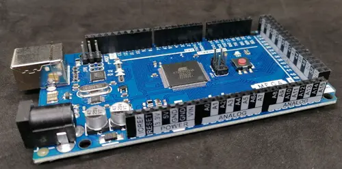
Funduino MEGA 2560 R3 - Buchsenleisten mit Pinbeschriftungen
Arduino UNO / Nano V3
Natürlich kannst du auch einen Arduino UNO oder Nano verwenden, diese haben lediglich nur einen seriellen Anschluss, und dieser ist beim Upload des Sketches belegt, somit musst du die Verbindungen (Breadboardkabel) vor dem Hochladen des Programmes entfernen. Alternativ kannst du auch die Bibliothek SoftwareSerial verwenden und somit zwei digitale Pins des Arduino UNOs als zusätzlichen seriellen Anschluss definieren.
Verbinden von zwei Mikrocontroller per serieller Schnittstelle
https://youtu.be/bEx_ASdbDXQ Die beiden Mikrocontroller kannst du auf verschiedene Wege verbinden, entweder per Bluetooth, nRF24L01, LoRa oder ganz einfach per serieller Schnittstelle. In diesem Beitrag verwende ich die serielle Schnittstelle, da dieses recht einfach ist und vor allem das eigentliche Projekt nicht zusätzlich durch Bibliotheken aufbläht.

zwei Arduino Mega per serieller Schnittstelle verbunden Auf der Grafik ist zu sehen, dass die Kontakte RX & TX jeweils über Kreuz verbunden sind.
Programmieren
Nachdem wir nun die beiden Mikrocontroller verbunden haben, kommen wir zur Programmierung. Wie erwähnt möchte ich eine Bibliothek zum Verarbeiten der JSON Daten verwenden. Bibliothek - Arduino_JSON Bevor wir mit der eigentlichen Programmierung beginnen, installieren wir die benötigte Bibliothek über den Bibliotheksmanager der Arduino IDE. Zunächst öffnen wir den Bibliotheksverwalter in der Arduino IDE (1) danach suchen wir nach "json" (2) und wählen an dem Eintrag "Arduino_JSON by Arduino" die Schaltfläche "INSTALL" (3). Wenn die Installation abgeschlossen ist, dann erscheint der Text "INSTALLED" (4).
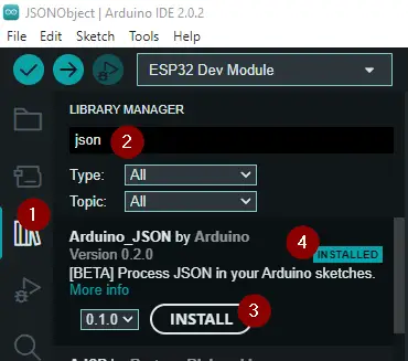
Installieren der Bibliothek Arduino_JSON über den Bibliotheksverwalter Parsen eines JSONs Zerlegen wir zunächst einmal auf einem Mikrocontroller ein kleines JSON. { "vorname":"Stefan", "nachname":"Draeger", "alter":42 } Damit wir dieses JSON in eine String Variable ablegen können, müssen wir alle Anführungszeichen escapen, d.h. wir setzen ein Backslash davor. {"vorname":"Stefan", "nachname":"Draeger", "alter":42} Nachfolgend ein kleines Programm zum Parsen von JSON Daten auf dem Arduino. // einbinden der Bibliothek zum verarbeiten von JSON #include // das JSON-Objekt welches verarbeitet werden soll String input = "{"vorname":"Stefan", "nachname":"Draeger", "alter":42}"; void setup() { // beginn der seriellen Kommunikation mit 9600 baud Serial.begin(9600); // initialisieren eines JSONVar Objektes // mit den verarbeiteten JSON Daten JSONVar jsonVar = JSON.parse(input); // prüfen ob es ein Key mit der Bezeichnung "vorname" gibt. if (jsonVar.hasOwnProperty("vorname")) { // Ausgeben der Zeichenkette "vorname:" auf der seriellen Schnittstelle Serial.print("vorname:"); // Ausgeben des Wertes zum Key Serial.println(jsonVar); } if (jsonVar.hasOwnProperty("nachname")) { Serial.print("nachname:"); Serial.println(jsonVar); } if (jsonVar.hasOwnProperty("alter")) { Serial.print("alter:"); Serial.println(jsonVar); } } void loop() { // bleibt leer } Die Ausgabe auf der seriellen Schnittstelle bzw. im seriellen Monitor sieht wie folgt aus:
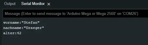
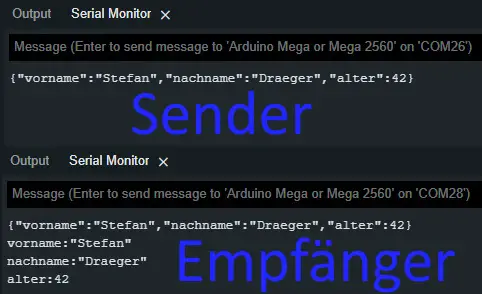
Übertragen eines JSON zwischen zwei Mikrocontroller per serieller Schnittstelle Im nächsten Schritt wollen wir ein JSON zwischen zwei Mikrocontroller übertragen. Das JSON könnte hier Sensordaten (Temperatur, Luftdruck, relative Luftfeuchtigkeit, CO₂ Konzentration etc.) enthalten. In meinem Fall möchte ich das JSON mit festen Daten beschreiben. Quellcode des Senders // einbinden der Bibliotheken zum verarbeiten // von JSON #include JSONVar output; void setup() { // beginn der seriellen Kommunikation mit 9600 baud Serial.begin(9600); Serial1.begin(9600); // einfügen des Schlüssel/Werte Paares in // das JSON-Objekt output = "Stefan"; output = "Draeger"; output = 42; // Umwandeln des JSON-Objektes in ein String String jsonOutput = JSON.stringify(output); Serial.print(jsonOutput); Serial1.print(jsonOutput); } void loop() { // put your main code here, to run repeatedly: } Quellcode des Empfängers Am Empfänger müssen wir "lauschen", ob Daten an der seriellen Schnittstelle anliegen und diese dann mit der Funktion "readString()" im Ganzen lesen. Diese gelesenen Daten parsen wir dann in ein JSON-Objekt und können diese, wie zuvor im einfachen Beispiel gezeigt, auswerten und ausgeben. // einbinden der Bibliotheken zum verarbeiten // von JSON #include void setup() { // beginn der seriellen Kommunikation mit 9600 baud Serial.begin(9600); Serial1.begin(9600); } void loop() { while (Serial1.available() > 0) { String data = Serial1.readString(); Serial.println(data); // initialisieren eines JSONVar Objektes // mit den verarbeiteten JSON Daten JSONVar jsonVar = JSON.parse(data); // prüfen ob es ein Key mit der Bezeichnung "vorname" gibt. if (jsonVar.hasOwnProperty("vorname")) { // Ausgeben der Zeichenkette "vorname:" auf der seriellen Schnittstelle Serial.print("vorname:"); // Ausgeben des Wertes zum Key Serial.println(jsonVar); } if (jsonVar.hasOwnProperty("nachname")) { Serial.print("nachname:"); Serial.println(jsonVar); } if (jsonVar.hasOwnProperty("alter")) { Serial.print("alter:"); Serial.println(jsonVar); } } } Hier nun die Ausgaben auf der seriellen Schnittstelle in der Arduino IDE.
Downloads
Hier der Quellcode zu den Beispielen aus diesem Beitrag zum bequemen Download. Read the full article
0 notes
Text
ESP32: serializing DS18B20 temperature measurement to MessagePack format
ESP32: serializing DS18B20 temperature measurement to MessagePack format

In this tutorial we will check how to obtain a temperature measurement from the DS18B20 sensor and serialize it using the MessagePack format. The tests were performed using a DFRobot’s ESP32 module integrated in a ESP32 development board and a waterproof version of the sensor.
(more…)
View On WordPress
0 notes
Text
マイコンスピードメーターの続き3

この投稿の続きです。 AdafruitさんのAdafruit_GFXライブラリとAdafruit_ST7735ライブラリを使ってTFT液晶に表示をするようにしたものです。描画が遅くて使えそうにありません。7セグメントLEDを使うか、もっと高速に描画できる仕組みに変えるなどを検討する必要があります。 ソースコードはGitHubに載せてあります。
View On WordPress
0 notes
Photo


API <--> Arduino
Toen de API werkte, ben ik als eerste begonnen met de connectie tussen de API en Arduino. Echter nadat ik had uitgevonden hoe ik een request kon versturen, moest ik de data verwerken binnen Arduino. Hier ben ik helaas vastgelopen.
Al snel bleek dat de ArduinoJSON library NIET goed samengaat met de Wifi101 library die gebruikt wordt voor de arduino MKR1000. Het parsen van de JSON lukt namelijk niet omdat de code niet wilt compilen. Het gaat fout ergens tussen de twee library’s en het object dat aangeroepen moet worden om de json te decoden. Andere manieren om de JSON te verwerken heb ik wel al geprobeerd maar ik heb nog geen goed werkende methode gevonden om mee verder te kunnen.
Nu ga ik dus eerst even verder met de app, zodat ik later weer met een frisse blik kan kijken naar het probleem.
0 notes
Text
ESP32 で HEOS デバイスを叩く
概要
最近のデノンやマランツのアンプはスマホアプリなどネットワーク経由で操作ができるので、実際に ESP32 を使って wifi 経由での操作を試してみました。
通信プロトコル
"HEOS Protocol" と検索すればデノン、マランツ、B&W などのダウンロード��ージがみつかりました。telnet でポート1255に接続してコマンドを送ると JSON フォーマットで応答が返ってくるようです。
用意するもの
ESP32 の開発基板
ブレッドボード・操作ボタン・ジャンパ
HEOS CLI Protocol Specification (仕様書)
Arduino IDE + esp32 + ArduinoJson
完成写真

サンプルコード
Pin14 に接続したボタンを押すと Mute on/off 切り替えするサンプル
ssid, password, heosdevice は要書き換え
HEOS デバイスが固定IPであることを前提としているので動的IPの場合は追加のコードが必要
#include <WiFi.h> #include <ArduinoJson.h> WiFiClient self; const char* ssid = "SSID"; const char* password = "PASSWORD"; const IPAddress heosdevice(192,168,1,40); const int heosport = 1255; volatile bool g_irq0 = false; char g_buf[1024]; long g_pid = 0; // 0 is handled as invalid void setup() { Serial.begin(115200); WiFi.begin(ssid, password); Serial.print("Connecting to "); Serial.println(ssid); while (WiFi.status() != WL_CONNECTED) { delay(500); Serial.print("."); } Serial.print("\r\nWiFi connected\r\n"); self.connect(heosdevice, heosport); Serial.print("Connecting to HEOS device\r\n"); if(self.connected()){ Serial.print("Connected\r\n"); self.print("heos://player/get_players\r\n"); int len = waitJsonResponse(); if(len>0){ g_pid = getPlayerId(g_buf); } Serial.print("Command: Get Players\r\n"); Serial.print("Response: "); Serial.write(g_buf, len); } pinMode(14, INPUT_PULLUP); attachInterrupt(digitalPinToInterrupt(14), setIRQ0, FALLING); } // @return length of a json packet. 0 if failed. size_t waitJsonResponse(){ int nestlevel = -1; size_t readlen = 0; while(1){ if (self.available()) { char c = self.read(); g_buf[readlen++] = c; if(c == '{'){ nestlevel++; }else if(c == '}'){ nestlevel--; if(nestlevel < 0){ break; } } if(nestlevel < 0){ // error (Invalid first character) return 0; } if(readlen >= 1024){ return 0; // error (Buffer limit) } } } return readlen; } long getPlayerId(char* buf){ StaticJsonDocument<256> doc; DeserializationError error = deserializeJson(doc, buf); if (error) { Serial.print("deserializeJson() failed: "); Serial.println(error.c_str()); return 0; } JsonObject payload_0 = doc["payload"][0]; long payload_0_pid = payload_0["pid"]; return payload_0_pid; } void loop() { if (self.available()) { char c = self.read(); Serial.print(c); } if(g_irq0){ Serial.print("toggleMute\r\n"); toggleMute(); g_irq0 = false; } } void setIRQ0(){ g_irq0 = true; } void toggleMute(){ if(!self.connected()){ return; } if(g_pid == 0){ return; } auto command = String("heos://player/toggle_mute?pid=") + String(g_pid) + String("\r\n"); auto len = command.length(); if(len>255){ return; } char buf[256]; command.toCharArray(buf, len+1); self.write(buf, len); return; }
0 notes
Text
Pixelstick logo

Pixelstick logo code#
Pixelstick logo professional#
If that is your case, try installing older versions of the app. Even in some rare cases, the re-install step also don't work.iOS usually provides an option to restore settings and content from iCloud backup, if you've enabled it previously. Finally, if you can't fix it with anything, you may need to uninstall the app and re-install it.After that put it to charge, and press the power button. If none of the above working, you can wait till your phone battery drains and it turns off automatically.Press the power off button for few seconds and then choose restart from the menu to restart your device.Now you can try opening the app, it may work fine. Then you close the app that has this issue. You just need to press the recent applications menu (usually the first left button) in your phone. Most of the times, it might be a temporary loading issue.Usually when you open an app, you will see a black screen for few seconds and then app will crash with or without an error message. It is one of the most common problem in mobile phones and tablets. jules.dukers liked DIY Beam-on-Target Fusion Particle Accelerator.Common PixelStick App Problems and Troubleshooting Steps ✅ I'm getting black screen / white screen (blank screen) when I open PixelStick?.jules.dukers liked Web security everywhere.Florian Festi wrote a reply on Boxes.py.kelvinA wrote a comment on project log Project Log 4: Not So Much Fun With FEA.micl has updated the project titled PicoPad.Charlie Lindahl liked Solar Powered WiFi Weather Station V4.0.Steven J Greenfield wrote a comment on Metrix Create:Space.Elliot Williams on As Europe Goes To LEDs, Scientists Worry.Darren on Better Mousetraps (or Screw Drives) Don’t Always Win.thoriumbr on Raspberry Pi Grants Remote Access Via PCIe (Sort Of).one on Mechanical Color Picker Types Hex Codes For You.70sJukebox on Raspberry Pi Grants Remote Access Via PCIe (Sort Of).Elliot Williams on 3D Printed String Vase Shows What’s Possible.Eric Chapin on Mechanical Color Picker Types Hex Codes For You.daveboltman on It’s Pi All The Way Down With This Pi-Powered Pi-Picking Robot.Alexandre on Mechanical Color Picker Types Hex Codes For You.Hackaday Podcast 185: A 2022 Rotary Phone, How AI Imagines Zepplin, Are We Alone In The Universe 1 Comment Posted in Arduino Hacks, LED Hacks Tagged addressable led, ESP8266, light painting Post navigation This isn’t the first LED light stick we’ve seen, if you’re interested in such things. There aren’t currently too many galleries of DIY LED-enabled light paintings, but we’d love to see some custom modded light painting approaches in the future. Some future improvements planned for the project include TFT/OLED support, rainbow or color gradient patterns in the LEDs, and accelerometer or gyroscope support for supporting animation. Images are drawn from the bottom row to the top, so images have to be transformed before updating to the LED painter.
Pixelstick logo code#
The project uses the Adafruit NeoPixel, ArduinoJson, and Bodmer’s TFT_HX8357 libraries for implementing the BMP drawing code, which also allows for an image preview prior to uploading the code to the microcontroller. The settings for the number of LEDs, time for the image row, and STA/AP-mode for wireless connections are also set by the web interface. Images are stored internally in Flash memory and are uploaded through a web interface. It directly supports 24-bit BMP, with no conversion needed. The LED Lightpainter takes the Pixelstick a few notches lower for amateur photographers and hobbyists. Nevertheless, it’s a huge step up from waving around a flashlight with your friends.
Pixelstick logo professional#
The equipment needed for setting up the light painting sticks runs in the order of hundreds, not to mention the professional camera and lenses needed. It’s actually based on the Pixelstick, a tool used by professional photographers for setting up animations and photorealism shots. This weekend project from uses an ESP8266-based microcontroller and an addressable WS2812-based LED strip to paint words or custom images in thin air. Light painting has long graced the portfolios of long-exposure photographers, but high resolution isn’t usually possible when you’re light painting with human subjects.
0 notes
Text
February 8, Arduino as API II & III - Reading data from web serial and reading from a joystick with web serial

We first started to look at how we can read the data from the web serial from the lecture slides. We were presented with an example of an Arduino and its joystick next to a canvas spleen. The canvas will visualize the space and position of the joystick to get an understanding of how the Arduino maps the visual space. To do this, we’ll need the ArduinoJson library again.
The sketch has some variables representing the axis of the joystick and when the button is pressed, then we see a function that makes a new JSON document. The serializeJson and serial.pintln(), the last one without arguments because this will send our Json and print a new line.
The Demo
Note: The code for the demo II is almost the same as the demo III:
Joystick and LED with Json.
The main goal here is to communicate bidirectionally with the Arduino. This is the concatenated version of the first two demos combined, the main difference is that we have more functions in our loop.
I have set these like steps, for my better understanding.
The alert to make sure we can connect the serial to the browser.
The serial connection, the button, the event listener, an asynchronous function and the await to get the port. Then the baud rate and a query selector to get our connection status, and our function to read JSON from Arduino, that has an asynchronous callback with no arguments to update the data display.
To get the function to read the JSON we need the text encoder function and the line buffer. The text encoder is there so it can get values from the serial to string. If we have a callback function here, it will run the callback. The parse line will pop into the state of the joystick.
We need something to update the data so we create another function that query selects the joystick state and shows in the HTML.
We add the canvas into the JavaScript. We need a map range, and the same update canvas function to clear the screen.
We get the ‘x’ and ‘y’ axis, and arrange it to fit in canvas.
We draw a circle, and change the color.
We update the canvas to request the animation frame with the update function, then the function that creates the canvas. and finally the state, with the writing and the reading part.
The point is to control the LED with our joystick from JavaScript because in the Arduino code there are no functions to do so. The Javascript will take the joystick inputs and send them back to communicate with the LED in Arduino, so when we write Json to Arduo the button of the joystick needs to be pressed. If not pressed we want to write from the brightness slider.
I managed to connect everything correctly, followed through every step of the way and everything worked. However, I do not feel so positive about getting to understand the canvas part just as well, although I have little experience using it in previous assignments. Certainly it is something I need to dig into more if I want to completely understand how everything gets done.
youtube
0 notes
Text
Mastering ArduinoJson: Efficient JSON serialization for embedded C++ by Benoit Blanchon [PDF EBOOK EPUB MOBI Kindle][Read] PDF Mastering ArduinoJson: Efficient JSON serialization for embedded C++ by Benoit Blanchon
Last access: 49089 user
Last server checked: 17 Minutes ago!
Click Here -> https://newaccessmedia.blogspot.com/media42.php?asin=B078NB88G3
FREE BOOKS were awesome to have as guests and did a great job on communicating on matters like check-in and check-out time. I can recommend them and I hope to have them again as guests. Mastering ArduinoJson: Efficient JSON serialization for embedded C++ by Benoit Blanchon.
Mastering ArduinoJson: Efficient JSON serialization for embedded C++ by Benoit Blanchon [PDF EBOOK EPUB MOBI Kindle]
Mastering ArduinoJson: Efficient JSON serialization for embedded C++ by Benoit Blanchon pdf d0wnl0ad
Mastering ArduinoJson: Efficient JSON serialization for embedded C++ by Benoit Blanchon read online
Benoit Blanchon by Mastering ArduinoJson: Efficient JSON serialization for embedded C++ epub
Mastering ArduinoJson: Efficient JSON serialization for embedded C++ by Benoit Blanchon vk
Mastering ArduinoJson: Efficient JSON serialization for embedded C++ by Benoit Blanchon pdf d0wnl0ad free
Mastering ArduinoJson: Efficient JSON serialization for embedded C++ by Benoit Blanchon d0wnl0ad ebook
Mastering ArduinoJson: Efficient JSON serialization for embedded C++ pdf
Mastering ArduinoJson: Efficient JSON serialization for embedded C++ by Benoit Blanchon amazon
Mastering ArduinoJson: Efficient JSON serialization for embedded C++ by Benoit Blanchon free d0wnl0ad pdf
Last access: 87865 user
Last server checked: 12 Minutes ago!
Last Online: 73427 user
Mastering ArduinoJson: Efficient JSON serialization for embedded C++ by Benoit Blanchon pdf free
Mastering ArduinoJson: Efficient JSON serialization for embedded C++ by Benoit Blanchon pdf
Mastering ArduinoJson: Efficient JSON serialization for embedded C++ by Benoit Blanchon epub d0wnl0ad
Mastering ArduinoJson: Efficient JSON serialization for embedded C++ by Benoit Blanchon online
Benoit Blanchon by Mastering ArduinoJson: Efficient JSON serialization for embedded C++ epub d0wnl0ad
Mastering ArduinoJson: Efficient JSON serialization for embedded C++ by Benoit Blanchon epub vk
Mastering ArduinoJson: Efficient JSON serialization for embedded C++ by Benoit Blanchon mobi
d0wnl0ad Mastering ArduinoJson: Efficient JSON serialization for embedded C++ PDF - KINDLE - EPUB - MOBI
Mastering ArduinoJson: Efficient JSON serialization for embedded C++ d0wnl0ad ebook PDF EPUB, book in english language
[d0wnl0ad] book Mastering ArduinoJson: Efficient JSON serialization for embedded C++ in format PDF
[PDF] [EPUB] Mastering ArduinoJson: Efficient JSON serialization for embedded C++ by Benoit Blanchon d0wnl0ad
synopsis of Mastering ArduinoJson: Efficient JSON serialization for embedded C++ by Benoit Blanchon
review online Mastering ArduinoJson: Efficient JSON serialization for embedded C++ by Benoit Blanchon
D0wnl0ad & Read Online Mastering ArduinoJson: Efficient JSON serialization for embedded C++ by Benoit Blanchon ->
https://newaccessmedia.blogspot.com/media13.php?asin=B078NB88G3
0 notes
Text
Activity board: It's all about the code!

With the activity board controller finally in place and tested. It's time to throw together the actual firmware. Let's fire up VSCode!
VSCode has been my code editor of choice for quite a while now. Microsoft did a great job in developing a light weight but super powerful code editor. And with the advent of a PlatformIO VSCode extension, this makes for THE perfect Arduino IDE.

That being said, It's time to start working on the final firmware. Or actually: the final firmware for now. Because the Activity Board will probably be a project which will receive some (software) updates over time.

All the board's functionality will be seperated into a bunch of controllers. There is no particular reason why I called them controllers, It just sounds like I know what I'm doing. For now, the code consists of the following 5 controller classes:
InputController: Responsible for reading all the switch states by communicating with the MCP23017 over I2C.
SevenSegmentController: Controls the 7-segment display by communicating with the MAX7219 seven segment display.
NeopixelController: Controls all the WS2812B RGB-LEDs using the FastLED library.
LedController: Controls all the regular LEDs (incorporated in some of the buttons) using the Arduino GPIO pins.
CommunicationController: Sends JSON commands (like the buttons state updates) to a Raspberry Pi using the ArduinoJson library.
All of the controller classes have a setup() method which is called in the main.cpp setup routine, and most of the controllers have an update() method which is being called during the main run loop.
All of the update() methods are non blocking, to make sure the Activity Board stays responsive. Any necessary delays are implemented by using the elapsedMillis library. But every so often, I just simply count the update ticks to check if I need to do something.
if (tick++ % 100 == 0) { // do something every 100th cycle. }

Most of the controllers are pretty straight forward, and are just there as an easy to use wrapper for the respective libraries. The only controller that is a bit more exotic, is the InputController. To be honest, this controller gave me some headaches.
Don't interrupt me!
The MCP23017 I2C IO expander is capable of firing interrupts whenever one of the inputs changes. Because of this, I connected the two interrupt outputs of the MCP23017 to the Arduino interrupt pins (Pin 2 & 3). It turned out I only needed to connect one, since the MCP23017 can mirror the interrupt signal on both pins. Luckily this was just resulted in a redundant connection, and didn't caused any issues.
Unfortunately there was a bigger problem which I didn't forsee. While the MCP23017 is capable of triggering the Arduino's interrupt pin(s), I'm not able to read out the pin states in the interrupt service routines, since I2C uses interrupts itself, which aren't available in the interrupt service routines.

This means I can set a flag to request an update in the main loop, but I can never act on any input change in the service routine itself. Now for most of the inputs this is absolutely no problem, but for the rotary encoder I really need to check the state for both pin A and B. Now, if these two pins were both connected to the two different MCP23017 registers, I could have solved this with the two Arduino Interrupt pins. Or better yet. If I would have just connected the Rotary encoder directly to the Arduino's interrupt pins, it would have been even easier. But of course ... I didn't.
So after a lot of grumbling, I decided to give up on the interrupts for the rotary encoder (for now), and simply read out the MCP23017 data every run loop. I might mean the encoder wouldn't react as expected, but I could always make some hardware modifications later.
And with taking this easy route, reading the MCP23017 state was pretty straight forward, using Mizraith's fork of the Adafruit MCP23017 library:
// Initialize the library. Adafruit_MCP23017 mcp; // Configure the MCP23017. mcp.begin(); // Use default address 0. mcp.setGPIOABMode(0xFFFF); // All ports input. mcp.setGPIOABPullUp(0xFFFF); // All ports pull up. // Read out the 16 bits. unsigned int newState = mcp.readGPIOAB();
And then it turned out I spent way to much time in overthinking it. Since non of my other controllers is blocking the main run loop, fetching the current state up the buttons every loop is easily fast enough to handle any rotary encoder input. Once again, it turns out KISS is the best approach: Keep It Simple, Stupid!
And with that issue out the way, it was a matter of hooking up all the controllers in my main.cpp file. Whenever an input change, execute an action for that specific input.

This setup really enables me to easily add more actions to any of the buttons. Now and in the future.
And by sending any input change as a json object over the serial port, I can continue using the inputs in my future Raspberry Pi implementation.
For now, it just resulted in one awesome looking activity board with a lot of light effects!
Enjoy the show!
youtube
Now, if you are interested in all the fine detail of the code, you can check out the full source code on GitHub. Of course it's fully supplied with unit and integration tests (NOPE!). And it's fully and well documented (NOPE!). Check it it out in the ActivityBoardController repository!
Read all posts in this series:
Part 1: Enzo’s Control Room Part 2: Building the Box Part 3: Fire up the Lasers! Part 4: Spray Away! Part 5: Push the button! Part 6: Assembling the panel Part 7: The dial on the board goes round and round Part 8: Take control! Part 9: It’s all about the code! Part 10: Bake me some Pi! Part 11: The Final Touch
#vscode#platformio#activity#board#activityboard#arduino#mcp23017#max7219#ws2812b#ws2812#neopixel#raspberrypi#led#rotaryencoder#interrupts
4 notes
·
View notes
Text
ESP32 ArduinoJSON: Printing prettified JSON string
In this ESP32 tutorial we will check how to print a JSON string in a prettified format, which makes it easier for a human to read. The tests shown here were performed using an ESP32 board from DFRobot.
Introduction
In this ESP32 tutorial
we will check how to print a JSON string in a prettified format, which makes it easier for a human to read.
We will be using the ESP32 and the ArduinoJson library.We have already covered in detail on this tutorial how to serialize JSON using the ESP32 and theArduinoJson library.
The code shown here will be very similar, except for the serializing function we will call at the end.So, instead of printing a minified JSON string without spaces and line breaks like we did in the previous post, the function we will call to serialize the JSON document will output a nicely formatted string with some spaces and line breaks.
Naturally, in a final application where we will be sending the JSON using some protocol (HTTP, websockets, etc..), it is more efficient to use the minified version.
Nonetheless, for debugging, it makes it much easier to interpret the JSON string if we use the approach shown on this tutorial.This tutorial targets version 6 of ArduinoJSON. The tests shown here were performed using an ESP32 board
from DFRobot.The codeWe will start by including the ArduinoJson.h library, so all the functionalities we need to serialize the JSON will become available.
#include <ArduinoJson.h>
Moving on to the Arduino setup function, we will start by opening a serial connection. We will later use it to output the JSON string.
Serial.begin(115200);
After that, we are going to declare an object of class StaticJsonDocument. Recall from the
previous tutorial
that this object will hold the memory representation of our object. This memory will be allocated on the stack.We need to specify the capacity of the StaticJsonDocument as a template parameter. The value is specified in bytes. We will use a value of 100, which is enough for our object. For a more accurate estimation, you can use this assistant.
StaticJsonDocument<100> testDocument;
Next we will take care of adding the members of our JSON. We are going to build the following structure, for testing purposes:
{ "sensorType": "temperature", "value": 10 }
To add members to our StaticJsonDocument we will use the [] operator, as shown below:
testDocument["sensorType"] = "Temperature"; testDocument["value"] = 10;
After this, we will need a buffer to hold the serialized string.
char buffer[100];
To obtain the JSON string in a prettified format, we only need to call the serializeJsonPretty function. As first input we pass our document and as second we pass the buffer we have just declared.This function will output the serialized JSON string to the char buffer.
serializeJsonPretty(testDocument, buffer);
After this, we will print to the serial port the prettified JSON string contained in the buffer.
Serial.println(buffer);
The final code can be seen below.
#include <ArduinoJson.h> void setup() { Serial.begin(115200); StaticJsonDocument<100> testDocument; testDocument["sensorType"] = "Temperature"; testDocument["value"] = 10; char buffer[100]; serializeJsonPretty(testDocument, buffer); Serial.println(buffer); } void loop() {}
Testing the codeTo test the code, simply compile it and upload it to your device using the Arduino IDE.
Once the procedure finishes, open the IDE serial monitor tool.You should get an output similar to figure 1. As can be seen, it prints the JSON string in a prettified format that makes it much easier to read.

Figure 1 – Output of the program, showing the prettified JSON string.
0 notes
Link
0 notes
Text
マイコンスピードメーターを作ろうか

そろそろ入れ替えを考えているオートバイ。XJR1300からもう少しタンデムでの長距離高速走行に向いているものを検討中です。 これまで交通違反と言えば速度超過のみ。他には助手席シートベルトをしていない違反をしたのみです。それほどスピードを出しているつもりはなくても大型バイクはスピードが出てしまうものです。検討している次期オートバイはXJR1300に比べてスピードが出るモデルなので、うっかりすると大変なことになります。…
View On WordPress
0 notes
Photo

This appears to run on some kind of alphabet. It is apparently an example for how to use ArduinoJson but the internet un-formatted it. http://bit.ly/2HcRYAM
0 notes
Text
Résumé de la semaine domotique et objets connectés du 7 au 11 septembre 2020
Résumé de la semaine, domotiques et objets connectés. Manipuler des objets #JSON avec du code #Arduino ou la librairie #ArduinoJSON v6. Comment mettre en veille et réveiller un #ESP32. Comment utiliser la mémoire #RTC de l'ESP32.
Le résumé de la semaine du 7 au 11 septembre 2020 en domotique et objets connectés. Comment sérialiser, désérialiser, manipuler des objets JSON avec du code Arduino ou la librairie ArduinoJSON v6. Comment optimiser l’alimentation sur batterie d’un projet ESP32 en activant la mise en veille. Toutes les méthodes pour réveiller un ESP32. Comment stocker temporairement des données dans la mémoire RTC…
View On WordPress
0 notes
Text
Controlling an Arduino-based car with Solace PubSub+ Event Broker
Let me start with a disclaimer that I am very new to Arduino. Despite having an Electrical Engineering degree, I had never really played around Arduino until very recently. The code referenced in this post was handed down to me by my colleagues at Solace.
Recently, I presented for the first time at Solace’s meetup in New York. For this meetup, we decided to cover a specific feature of Solace PubSub+ which we thought our users and prospects would find interesting: Replay. PubSub+’s Replay feature is relatively new but extremely powerful and one that many users have welcomed.
Every meetup’s success depends on two factors:
Food and drinks
Demo
Food and drinks were a no-brainer. We got a bunch of delicious pizza and lots of craft beer (lagers, pilsners, sours, and even rosé cider!).
However, having a cool demo for your meetup requires a lot of planning. We could have easily demoed Replay via PubSub+ admin UI. While it would have gotten the point across, it wouldn’t have been visually appealing. After a lot of discussions, we decided to use a car powered by Arduino and controlled by PubSub+. The idea was simple and visually appealing. We would build an Arduino-powered car and control it by sending MQTT messages via PubSub+. Then, we will replay those messages and show the car repeating its earlier steps (this is when the crowd goes “oooh aaaah”).
In this post, I would like to show you how you can build your own Arduino-powered car and control it with PubSub+ Event Broker. Let’s get started.
Here are the steps to achieve our goal:
Assemble car from the car kit
Configure code and upload to Arduino chip
Send messages to control the car
Assemble Car from the Car Kit
I don’t want to document all the steps I followed to assemble the car because, to be honest, I was just following instructions from other blogs. The instructions that came with the kit were not very helpful and very difficult to understand.
You can buy the kit from Amazon. More details about the kit can be found on this site. This YouTube video was very helpful and I highly recommend using it as a starting point.
The assembled car should look like this:
Configuring Code and Uploading to Arduino Chip
Once you have the car assembled, it is time to upload code to the Arduino chip. You can find the code on Solace’s github. In the repo, you will find car_demo/arduino/src/car_kit.ino which is the code that you will need to open using Arduino IDE and upload it to chip. Note that the following instructions are meant for the ESP8266 chip only.
Downloading Arduino IDE
To be able to upload code to the chip, you will need to download and use the Arduino IDE. I recommend downloading the software instead of just using the browser version. Once installed, open car_kit.ino in the Arduino IDE.
Configuring code
Before you can upload the code, you need to modify the code slightly to get it to work for you. You need to make a minimum of two changes:
Enter wifi details so the chip can connect to the Internet
Enter MQTT broker details
Modify the following lines by entering your Wifi details:
const char* ssid = "<ssid>";const char* password = "<ssid_pwd>";
Modify the following lines by entering your MQTT broker details:
const char* mqttServer = ""; const int mqttPort = ; const char* mqttUser = ""; const char* mqttPassword = "";
You will need an MQTT broker running so you can enter the relevant connection settings. Of course, I would recommend using Solace’s PubSub+ Event Broker which supports MQTT. You can spin up an instance via Solace Cloud for free.
Configuring board
Before uploading this code to your Arduino chip, you will need to configure your IDE to work with the specific model of your chip as well as install PubSubClient and ArduinoJson libraries.
Arduino IDE supports a lot of ‘boards’/chips out-of-box but sadly, doesn’t support the ESP8266 chip. So, we need to add it manually to Arduino’s Board Manager. To do so, go to Arduino > Preferences and enter the URL: https://ift.tt/1N7Vwyq
Click OK.
Now, go to Tools > Boards > Boards Manager, and search for ESP8266. You will now see ESP8266 board by ESP8266 Community. Click on Install to install it. You can also choose to install a specific version if needed. We are using 2.6.3 currently.
Installing necessary libraries
Now, you are ready to install PubSubClient and ArduinoJson libraries. You can easily do that by going to Tools > Manage Libraries and simply searching for them and installing them.
Once you have these libraries installed, you are ready to upload the code to the Arduino chip. Plug your chip into your computer via Micro USB cable. You will see a blue LED light as soon as you plug in the chip. If you don’t see the light, try toggling the white switch on the chip to turn it on.
Finally, go to Sketch > Upload to upload the code to your chip.
That’s it!
Sending MQTT messages via PubSub+
You can now go to PubSub+ UI and send some sample messages to your chip to control the car.
Getting the Chip ID
If you are using the exact code from car_kit.ino, you will need to publish messages to car/drive/${chipID} topic where chipID is your Chip’s ID. You can get the Chip ID by looking at the output of your code in the Serial Monitor. To be able to run the Serial Monitor from Arduino, you will need to make sure your chip is plugged in via USB to your laptop. When you upload the code, you can run the Serial Monitor to see the output.
Here is the output of my Serial Monitor:
As shown in the screenshot above, my Chip ID is 6994174.
Here is some good documentation on how to use Arduino’s Serial Monitor.
Sending MQTT Messages
The payload of your message should be in JSON format and should include three values:
l – power for the left motor with a range of -100 to 100
r – power for the right motor with a range of -100 to 100
d – duration in milliseconds
Negative power will make the motor turn in the opposite direction compared to positive power. For example, l:100, r:100 and d:500 will make the car move forward for 500 milliseconds. If you want to turn right, you can set l to 0 and if you want to turn left, you can set r to 0, respectively. You can control how far the car drives by adjusting the duration (d) parameter.
Here is a sample payload:
{ "l": 100, "r": 100, "d": 700 }
Solace PubSub+ Try Me! Publisher
It’s up to you how you would like to publish these JSON messages. For development, you can simply use Solace’s Try Me! tab and use the Publisher app there to publish these messages.
Of course, you can build a nice shiny app or program a joystick to send such messages. It’s up to you how creative you want to get!
Architecture
Now that we have our car running, let’s take a step back and look at the architecture of our setup:
On the left side, we have our assembled car powered by an Arduino chip and subscribing to an MQTT topic with QoS 1. You can see where we specify the subscription in the code:
// Subscribe to car specific drive commands char carDriveTopic[40]; sprintf(carDriveTopic, "car/drive/%lu", chipId); client.subscribe(carDriveTopic, 1);
As you can see, we are subscribing to car/drive/${chipId} with QoS of 1. Specifying QoS to be 1 causes PubSub+ to create an internal queue and map car/drive/${chipId} topic to the queue. When we publish JSON messages to the car/drive/${chipId} topic, our messages are sent to the queue and then to the Arduino chip.
On the right side, we have our Controller UI which is simply the javascript Publisher app on Try Me! tab on Solace Cloud.
Needless to say, the MQTT broker being used here is Solace’s PubSub+ Event Broker running on AWS.
That’s pretty much it! I hope you found this post useful. For more information, visit PubSub+ for Developers. If you have any questions, post them to the Solace Developer Community.
The post Controlling an Arduino-based car with Solace PubSub+ Event Broker appeared first on Solace.
Controlling an Arduino-based car with Solace PubSub+ Event Broker published first on https://jiohow.tumblr.com/
0 notes