#ESP32 Tutorial IoT
Explore tagged Tumblr posts
Visit Tumblr Blog
Explore Tumblr blogs with no restrictions, modern design and the best experience.
Last Seen Tumblr Blogs


Fun Fact
In 2020, 44% of users from Denmark used Tumblr daily.
Text

SunFounder ESP32 Ultimate Starter Kit – All-in-One IoT Learning Platform for Every Level
Discover the SunFounder ESP32 Ultimate Starter Kit – perfect for beginners and pros. Learn IoT, home automation, Bluetooth, and camera projects with 50+ tutorials and multi-language coding support.
1 note
·
View note
Text
Creating a Go-Based IoT Project with MQTT and ESP32
Introduction Creating a Go-Based IoT Project with MQTT and ESP32 is an exciting and challenging endeavor that combines the power of IoT, messaging protocols, and a popular programming language. In this tutorial, we will guide you through the process of building a comprehensive IoT project using Go, MQTT, and the ESP32 microcontroller. What Readers Will Learn The basics of Go programming…
0 notes
Link
In this tutorial, we will walk you through the process of displaying your YouTube subscriber count on a MAX7219 8-Digit 7-Segment Display using an ESP32 Node MCU. Whether you’re a YouTuber looking to showcase live stats or an electronics enthusiast diving into IoT projects, this step-by-step guide is for you!
0 notes
Text
How to Learn Embedded Systems: A Comprehensive Guide
Embedded systems are integral to countless applications, from consumer electronics to industrial automation. Understanding how to learn embedded systems can open up a world of opportunities in various fields, including robotics, automotive, healthcare, and IoT. Here’s a structured approach to mastering embedded systems.

1. Understanding the Basics
Start with the fundamentals of embedded systems. Familiarize yourself with key concepts such as:
What are Embedded Systems?
Embedded systems are specialized computing systems that perform dedicated functions within larger mechanical or electrical systems. Unlike general-purpose computers, they are designed to execute specific tasks with high reliability.
Components of Embedded Systems:
Microcontrollers and Microprocessors: Understand the difference between the two. Microcontrollers are compact integrated circuits designed to govern a specific operation in an embedded system, while microprocessors are the central unit of a computer that performs calculations and logic operations.
Memory: Learn about different types of memory (RAM, ROM, Flash) used in embedded systems.
Input/Output Devices: Familiarize yourself with sensors, actuators, and communication interfaces (UART, SPI, I2C).
2. Choose Your Learning Resources
Select resources that match your learning style. Here are some options:
Books:
"Embedded Systems: Introduction to the MSP432 Microcontroller" by Jonathan Valvano
"Programming Embedded Systems in C and C++" by Michael Barr
Online Courses:
Platforms like Coursera, Udemy, and edX offer courses in embedded systems. Look for those that cover microcontrollers, programming, and interfacing.
YouTube Channels:
Channels like "The DIY Life" and "NPTEL" provide practical insights and tutorials on embedded systems.
3. Get Hands-On Experience
Theory is essential, but hands-on practice is crucial for mastering embedded systems. Consider the following:
Development Boards:
Start with popular development boards like Arduino, Raspberry Pi, or ESP32. These platforms are beginner-friendly and have extensive community support.
Build Projects:
Create simple projects like LED blinkers, temperature sensors, or motor controls. Gradually move to more complex projects like home automation systems or robotic applications.
Use Simulation Tools:
Familiarize yourself with simulation tools like Proteus or MATLAB/Simulink for testing your designs virtually.
4. Learn Programming Languages
Embedded systems often require programming skills. Focus on:
C/C++ Programming:
C is the most commonly used language for embedded systems due to its efficiency and control over hardware. Learn the syntax, data structures, and memory management.
Assembly Language:
Understanding assembly language can provide deeper insights into how microcontrollers operate.
5. Explore Real-Time Operating Systems (RTOS)
Many embedded systems require multitasking and real-time performance. Learning about RTOS concepts can be beneficial:
Understand the Basics:
Familiarize yourself with the concepts of task scheduling, inter-task communication, and resource management.
Hands-On with RTOS:
Try using an RTOS like FreeRTOS or Zephyr on your development board. Implement multitasking projects to get practical experience.
6. Join Online Communities
Engaging with fellow learners and professionals can enhance your learning experience:
Forums and Discussion Groups:
Platforms like Stack Overflow, Reddit, and specialized forums (e.g., Embedded Related) are great for seeking help and sharing knowledge.
Attend Workshops and Webinars:
Participate in online workshops or local meetups to learn from experts and network with peers.
7. Stay Updated with Industry Trends
The field of embedded systems is constantly evolving. Keep yourself updated with the latest trends and technologies:
Follow Industry News:
Subscribe to blogs, newsletters, and magazines related to embedded systems.
Participate in Hackathons:
Engage in hackathons or coding competitions focused on embedded systems to test your skills and learn from others.
Conclusion
Learning embedded systems requires a mix of theoretical knowledge and practical experience. By following this structured approach—starting from the basics, choosing the right resources, getting hands-on experience, and staying engaged with the community—you can build a strong foundation in embedded systems. Whether you aim to work in robotics, IoT, or automation, mastering embedded systems can significantly enhance your career prospects. Start your journey today, and embrace the exciting world of embedded systems!
0 notes
Text
How do I start my home automation project with iot at low cost?
Take into account the following steps to start an inexpensive IoT home automation project. First, establish your objectives. List the appliances and processes, such lighting, thermostats, or security cameras, that you wish to automate. Choose open-source solutions with flexibility and device interoperability, such as Home Assistant or OpenHAB.
Next, choose IoT devices from embedded that are being classified as automotive embedded or electric vehicles embedded affordable and compatible with your preferred platform. Affordable smart switches and sensors are offered by companies like Sonoff and Shelly. For device communication, use well accepted protocols like MQTT to ensure easy integration.Repurpose current hardware: The controllers can be Raspberry Pi boards or old iPhones. Utilise cloud services that are free or inexpensive, such as Blynk or Cayenne, for remote access. Investigate do-it-yourself options for creating unique sensors or actuators using Arduino or ESP8266/ESP32 boards.
Use tutorials, forums, and internet tools to educate oneself. There is a wealth of knowledge available on IoT and home automation projects on websites like YouTube and GitHub. Engage the neighbourhood to resolve problems and learn more.Consider security when using strong passwords and frequently updating device firmware. As necessary, gradually extend your system while balancing usefulness and expense. With this strategy, you may create a personalised home automation system while keeping costs down and acquiring important IoT experience.
1 note
·
View note
Text
Tutorial Lengkap Membuat Smart Home dengan Arduino
Tutorial Lengkap Membuat Smart Home dengan Arduino
Membuat smart home berbasis arduino dan internet of things (iot) merupakan pilihan yang tepat dengan harga yang sangat terjangkau, artikel ini akan mengupas tuntas tutorial membangun projek smart home dengan arduino, esp8266, esp32, bluetooth dan wifi. Arduino IDE merupakan software open source yang dibangun dengan berbagai macam bahasa pemograman seperti Java, C++, C dan Python. dengan…
View On WordPress
#ESP32 Smart Home IoT#ESP32 Tutorial IoT#Firebase Arduino#Firestore Arduino#Smart Home ESp32#Tutorial Smart Home Arduino
0 notes
Text
A Camunda Greenhouse, part 3
A Camunda Greenhouse, part 3
Review If you’ve been following this (incredibly slow) project, then you’ve already been through part 1 and part 2 and have been wondering if part 3 would ever arrive. Well, here it is! This is the part where I pull together all the previous parts and actually deploy a Camunda BPMN-powered IoT Greenhouse! Just to review a bit, I proposed building a greenhouse, monitored by some IoT sensors, that…

View On WordPress
#arduino#automation#bpmn#ESP32#go language#golang#iot application#iot application development#tutorial
0 notes
Text
ESP32 Chat Application (Part 5)
ESP32 Chat Application (Part 5)
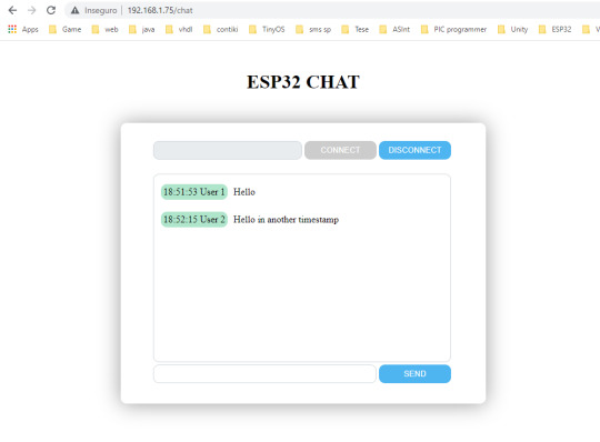
Introduction In this part we will add some new events to the chat application. More precisely, we will start sending an event when a new user joins the chat and when a user leaves the chat. Both will be displayed in the chat div, together with the messages. Since we have already added timestamping to the messages in part 4 of our series of tutorials, we will leverage what was already…

View On WordPress
1 note
·
View note
Text
Liked on YouTube: Powerful Alternative to ESP32 CAM | Realtek AMB82-Mini IoT AI Camera Board - Getting Started
Powerful Alternative to ESP32 CAM | Realtek AMB82-Mini IoT AI Camera Board - Getting Started 𝗔𝗺𝗲𝗯𝗮 𝗔𝗿𝗱𝘂𝗶𝗻𝗼 𝗦𝗗𝗞 𝗽𝗮𝗴𝗲: https://ift.tt/blXFw0c 𝗣𝘂𝗿𝗰𝗵𝗮𝘀𝗲 𝗟𝗶𝗻𝗸: https://ift.tt/O3HePEl 𝗣𝗿𝗼𝗷𝗲𝗰𝘁 𝗗𝗲𝘀𝗰𝗿𝗶𝗽𝘁𝗶𝗼𝗻: In today's exciting video, we're exploring a power-packed product from Realtek, the AMB82-Mini. This little beast is essentially an IoT AI Camera Arduino Development Board and an impressive replacement for the ESP32 Camera Module. Designed with Artificial Intelligence, Machine Learning, and Neural Networks in mind, the AMB82-Mini boasts ultra-low power consumption. This makes it incredibly efficient and ensures you won't have to worry about draining your power supply. What makes this board special? It features an HDR Camera with a crisp 1080p resolution, superior to the ESP32 CAM. The CPU speed is a whopping 500MHz, more than double the ESP32's 240MHz. The AMB82-Mini supports both 2.4 GHz and 5GHz Wi-Fi bands, and also includes a BLE chip that enables Bluetooth Low Energy 5.1. Storage? We've got 768KB ROM, 512KB RAM, 16MB Flash, and support for MCM embedded DDR2/DDR3L memory up to 128MB. Power-packed, isn't it? In this tutorial, we'll be diving deep into the board design, pin descriptions, features, and capabilities of this remarkable board. We'll also walk you through setting up the Arduino IDE and how to program the AMB82-Mini using this platform. What's more, we'll get hands-on with some practical exercises like making an LED blink, video streaming over a Web server, Object Detection and Identification, and 1080p Video recording. So, if you're ready to explore the possibilities of IoT, AI, and Machine Learning with this powerful board, hit that play button, and let's get started! Don't forget to like, share, and subscribe for more tech tutorials and updates. Your support keeps us going! #AMB82Mini #Realtek #IoT #Arduino #AI #machinelearning 𝗪𝗿𝗶𝘁𝘁𝗲𝗻 𝗧𝘂𝘁𝗼𝗿𝗶𝗮𝗹 𝙇𝙞𝙣𝙠𝙨: 𝟭. 𝗚𝗲𝘁𝘁𝗶𝗻𝗴 𝗦𝘁𝗮𝗿𝘁𝗲𝗱: https://ift.tt/WVai2or 𝟮. 𝗢𝗯𝗷𝗲𝗰𝘁 𝗗𝗲𝘁𝗲𝗰𝘁𝗶𝗼𝗻 & 𝗜𝗱𝗲𝗻𝘁𝗶𝗳𝗶𝗰𝗮𝘁𝗶𝗼𝗻: https://ift.tt/lG3HtQ2 𝟯. 𝟭𝟬𝟴𝟬𝗽 𝗠𝗣𝟰 𝗩𝗶𝗱𝗲𝗼 𝗥𝗲𝗰𝗼𝗿𝗱𝗲𝗿: https://ift.tt/ni4OlpS .................................................................................................................................................................................................................................... Drop a like if you liked this video. Don't forget to subscribe to our channel for more Electronics projects and tutorials. Website: https://ift.tt/L7raVJs Facebook: https://ift.tt/EFchGia Instagram: https://ift.tt/tQKdAHY Twitter: https://twitter.com/how2electronics via YouTube https://www.youtube.com/watch?v=vI6GZMLfGQk
0 notes
Text
Basic Understanding of Microcontroller
Understanding of Microcontroller
Hello and welcome to my blog! Today I’m going to talk about one of my favorite topics: microcontrollers. If you are interested in electronics, robotics, or IoT, you should definitely learn more about these amazing devices.
A microcontroller is a small computer that can be programmed to perform specific tasks. Unlike a general-purpose computer, a microcontroller is designed for a specific application and has limited resources. For example, a microcontroller may have only a few kilobytes of memory and run at a few megahertz. However, this also makes them cheaper, smaller, and more energy-efficient than regular computers.
A microcontroller consists of three main components: a central processing unit (CPU), a memory unit, and an input/output unit. The CPU is the brain of the microcontroller that executes the instructions stored in the memory. The memory unit stores the program code and data that the CPU needs. The input/output unit allows the microcontroller to interact with other devices, such as sensors, actuators, displays, or communication modules.
To program a microcontroller, you need to write code in a programming language that the microcontroller can understand. The most common languages are C and assembly, but there are also other options such as Python, Arduino, or Scratch. You also need a software tool called an integrated development environment (IDE) that helps you write, compile, and upload your code to the microcontroller. Some popular IDEs are Arduino IDE, MicroPython IDE, and MPLAB X IDE.
Once you have your code ready, you need to connect your microcontroller to your computer using a cable or a wireless connection. Then you can use the IDE to upload your code to the microcontroller’s memory. After that, you can disconnect your microcontroller and power it with a battery or another source. Your microcontroller will then run your code and perform the task you programmed it to do.
There are many types of microcontrollers available in the market, each with different features and capabilities. Some of the most popular ones are Arduino, Raspberry Pi, ESP32, STM32, PIC, and AVR. You can choose the one that suits your needs and budget best.
Microcontrollers are fun and versatile devices that can be used for many projects and applications. You can use them to create robots, smart home devices, musical instruments, games, wearable gadgets, and more. The only limit is your imagination!
If you are interested to understand more about the Microcontroller, then you can go through the PiEmbSysTech Microcontroller Tutorial Blog. If you have any questions or query, that you need to get answer or you have any idea to share it with the community, you can use Piest Forum.
I hope you enjoyed this blog post and learned something new about microcontrollers. If you have any questions or comments, please leave them below. Thank you for reading and happy coding!
1 note
·
View note
Text
Will show you how to use BLE communication in ESP32 Controllers. Things used in this project Hardware componentsM5Stack M5StickC ESP32-PICO Mini IoT Development BoardM5Stack - M5Stamp PICO×1Arduino 101×1Software apps and online servicesArduino IDE Story Hey, what's up, Guys! Pradeep here In this tutorial, I'm going to show you how to trigger actions with Bluetooth using M5Stamp PICO and M5Stick C which are very cheap and High efficient ESP32 Controllers. Components Required: M5Stick C M5Stamp PICO What are M5Stick and M5Stamp? M5Stack is a technology company that designs and manufactures anopen-source development toolkit, including hardware, programming platform, and IoT solutions. It was founded by Jimmy Lai in 2017 and isbased in Shenzhen, China. M5Stack created the M5Stick and M5Stamps, which are both based on the ESP32 controller. The M5Stick C features an embedded TFT display and battery, while the M5Stamp has a small footprint and can be used in a variety of IoT products. M5StickC is a mini M5Stack, powered by ESP32. It is a portable, easy-to-use, open-source, IoT development board. It is an ESP32 development board with 0.96 inch TFT color screen (80 * 160 resolution), Red LED, button, Microphone, IR transmitter, 6-axis IMU (SH200Q), and 80 mAH battery. The ESP32 module ESP32-Pico in M5StickC also has a built-in 4MB flash. If the M5StickC is equipped with a watch base and watch belt, you can wear it on your wrist. It is built in a continually growing hardware and software ecosystem. It has a lot of compatible modules and units, as well as the open-source code & engineering communities that will help you maximize your benefits in every step of the developing process. Power switch operation: Power on: Press the power button for 2 seconds Power off: Press the power button for 6 seconds The input range of VBUS_VIN and VBUS_USB is limited to 4.8-5.5V, and the internal battery will be charged through AXP192 power management when VBUS is powered. STAMP-PICO features an ultra-compact design with two low-power Xtensa® 32-bit LX6 microprocessors at 240MHz on a PCB as tiny and delicate as a postage stamp. low power consumption. It is ideal for any space-constrained or battery-powered devices such as wearables, medical devices, sensors, and other IoT devices. 1, MULTIFORM: 5 options of installation, means endless possibilities! (SMT, DIP, flywire, grove interface), with a high-temperature resistant plastic shell, 3D antenna and components can be better protected. 2, LOW-CODE DEVELOPMENT: STAMP-PICO supports UIFlow graphical programming platform, scripting-free, cloud push; and fully compatible with Arduino, MicroPython, ESP32-IDF, and other mainstream development platforms to quickly build various applications. 3, HIGH INTEGRATION: STAMP-PICO contains a 5V->3.3V DC/DC port, GPIOx12, programmable RGB light x1, button x1, and finely tuned RF circuit, providing stable and reliable wireless communication. 4, STRONG EXPANDABILITY: Easy access to M5Stack's hardware and software ecology system: a wealth of sensors, actuators, functional modules, and accessories to choose from, and Extremely fast adaptation. Set up M5Stamp and M5Stick with Arduino IDE by following these instructions. https://docs.m5stack.com/en/quick_start/m5core/arduino Flow : M5Stick C will act as a BLE transmitter, while M5Stamp PICO will act as a BLE receiver. When Button A on the M5Stick is pressed, the M5Stamp's LED turns green. Coding for Transmitter: #include #include "BLEDevice.h" #include "BLEUtils.h" #include "BLEServer.h" #include "BLEBeacon.h" BLEAdvertising *pAdvertising; // BLE Advertisement type struct timeval now; #define GPIO_DEEP_SLEEP_DURATION 1 // sleep x seconds and then wake up RTC_DATA_ATTR static time_t last; // remember last boot in RTC Memory RTC_DATA_ATTR static uint32_t bootcount; // remember number of boots in RTC Memo
ry #define BEACON_UUID "87b99b2c-90fd-11e9-bc42-526af7764f64" // UUID 1 128-Bit (may use linux tool uuidgen or random numbers via https://www.uuidgenerator.net/) void setBeacon() BLEBeacon oBeacon = BLEBeacon(); oBeacon.setManufacturerId(0x4C00); oBeacon.setProximityUUID(BLEUUID(BEACON_UUID)); oBeacon.setMajor((bootcount & 0xFFFF0000) >> 16); oBeacon.setMinor(bootcount & 0xFFFF); BLEAdvertisementData oAdvertisementData = BLEAdvertisementData(); BLEAdvertisementData oScanResponseData = BLEAdvertisementData(); oAdvertisementData.setFlags(0x04); // BR_EDR_NOT_SUPPORTED 0x04 std::string strServiceData = ""; strServiceData += (char)26; // Len strServiceData += (char)0xFF; // Type strServiceData += oBeacon.getData(); oAdvertisementData.addData(strServiceData); pAdvertising->setAdvertisementData(oAdvertisementData); pAdvertising->setScanResponseData(oScanResponseData); void setup() M5.begin(); Serial.begin(115200); M5.Lcd.setTextColor(YELLOW); //Set the font color to yellow. 设置字体颜色为黄色 M5.Lcd.setRotation(3); M5.Axp.ScreenBreath(10); M5.Lcd.setTextColor(RED); M5.Lcd.setCursor(3, 10); M5.Lcd.setTextSize(2); void loop() M5.update(); M5.Lcd.setCursor(3, 10); if (M5.BtnA.wasReleased()) M5.Lcd.setTextColor(GREEN); M5.Lcd.println("Triggred"); Serial.println("Trigger mode"); // Create the BLE Device BLEDevice::init("BLE Receiver 01"); // Create the BLE Server BLEServer *pServer = BLEDevice::createServer(); // start(); Serial.println("Advertizing started..."); delay(1000); pAdvertising->stop(); M5.Lcd.fillScreen(BLACK); M5.Lcd.setCursor(3, 10); Upload the above code to your M5Stick C Controller. Coding for Receiver: #include "Arduino.h" #include #include #include #include #include // How many leds in your strip? #define NUM_LEDS 1 #define DATA_PIN 27 // Define the array of leds CRGB leds[NUM_LEDS]; String knownBLEAddresses[] = "24:a1:60:53:06:3e"; int RSSI_THRESHOLD = -100; bool device_found; int scanTime = 1; //In seconds BLEScan* pBLEScan; class MyAdvertisedDeviceCallbacks: public BLEAdvertisedDeviceCallbacks void onResult(BLEAdvertisedDevice advertisedDevice) for (int i = 0; i < (sizeof(knownBLEAddresses) / sizeof(knownBLEAddresses[0])); i++) if (strcmp(advertisedDevice.getAddress().toString().c_str(), knownBLEAddresses[i].c_str()) == 0) device_found = true; break; else device_found = false; Serial.printf("Advertised Device: %s \n", advertisedDevice.toString().c_str()); ; void setup() Serial.begin(115200); //Enable UART on ESP32 FastLED.addLeds(leds, NUM_LEDS); // GRB ordering is typical Serial.println("Scanning..."); // Print Scanning BLEDevice::init(""); pBLEScan = BLEDevice::getScan(); //create new scan pBLEScan->setAdvertisedDeviceCallbacks(new MyAdvertisedDeviceCallbacks()); //Init Callback Function pBLEScan->setActiveScan(true); //active scan uses more power, but get results faster pBLEScan->setInterval(100); // set Scan interval pBLEScan->setWindow(99); // less or equal setInterval value void loop() BLEScanResults foundDevices = pBLEScan->start(scanTime, false); for (int i = 0; i < foundDevices.getCount(); i++) BLEAdvertisedDevice device = foundDevices.getDevice(i); int rssi = device.getRSSI(); Serial.print("RSSI: "); Serial.println(rssi); if (rssi > RSSI_THRESHOLD && device_found == true) Serial.println("Triggred"); leds[0] = 0xf00000; FastLED.show(); delay(200); // Now turn the LED off, then pause leds[0] = 0x00f000; FastLED.show(); delay(200); pBLEScan->clearResults(); // delete results fromBLEScan buffer to release memory In the above code, you have to change the BLE Address of your M5Stick C. Here I have added my M5Stick C's BLE Address. Change th
is according to yours. Outcome: Once the Transmitter and Receiver codes have been uploaded to the M5Stick and M5Stamp, connect the M5Stamp to your PC and open the serial monitor, then click the button A on the M5Stick C, which will display Triggered on the TFT Display. Check the Serial Monitor Results whenever you see a triggered message in your M5Stick C. The name of the ESP Transmitter, RSSI, and Triggered Message will be displayed on the serial monitor. The Green led on the M5Stamp will blink. The Green led will blink every time the button is pressed. Code Github repository for the project Repo not found. Make sure the repo is public!
0 notes
Text
Arduino camera code

#Arduino camera code how to#
#Arduino camera code serial#
#Arduino camera code software#
Hope this will give you some idea about using ultrasonic sensor with arduino using Python. Once all these settings are done, When you run the program Ultrasonic sensor will find the obstacles in an interval and capture the images using the camera. 2) Go to Tools > Port and select the COM port the ESP32-CAM is connected to. Otherwise, this board won’t show up on the Boards menu. You must have the ESP32 add-on installed. In this tutorial we will interface most widely used camera module OV7670 with Arduino UNO. After finish uploading demo code, we can take a photo now, just press the button.
#Arduino camera code how to#
Arduino port name is shown in arduino ide choose Tools => Port => Port name is shown in ide To upload code to the ESP32-CAM using Arduino IDE, follow the next steps: 1) Go to Tools > Board and select AI-Thinker ESP32-CAM. How to Use OV7670 Camera Module with Arduino. Its a great camera for Arduino centered image recognition projects. If data python “Your python project name”/arduino port name(example : python self.py /dev/ttys0 ). One string is typically output on every video frame, that is, these strings are coming out of the JeVois camera at rates of 30 per second, 60 per second, or. String, in order to process futher, it is converted
#Arduino camera code serial#
The value received through serial interface would be Starts the camera, Captures the image, saves it & amp amp amp amp amp amp amp stopsįile_name = home_dir + ‘/image_captured/image_’ + str(dt.now()) + ‘.jpg’Įstablishes a connection to Arduino board through serial interfaceĪrduino_board = serial.Serial(sys.argv, 9600)Įnters an infite loop that runs until it receives Keyboard Interrupt Python program is used for getting the input signal from sensor via arduino, so that it can capture the obstacle according to the sensor detection.Ĭam = (“/dev/video0″, (640, 480)) // Here we declare the arduino portĪdjust the value of this variable to set the distance Open unzipped file of CameraVC0706TEST, and the program the code. Arduino codeĪrduino will receive the signal from Ultrasonic and given the signal input to python. Put the unzipped file of CameraVC0706lib into the Arduino IDE folder of Libraries. Similar to ArduCAM-Mini example, see section 3.1. 4 ArduCAM Shield V2 Examples 4.1 ArduCAMCameraPlayback. And examples also work with ArduCAM-Nano-ESP8266 module. Open arduino ide and paste the arduino code into ide and upload the program into UNO. All of the examples are designed for different camera modules, and will take effect automatically according to the Macro definition in the memorysaver.h file. Connection :Ĭonnect your arduino 12th and 11th pin to sensor Trigger pin and Echo pin, arduino +5v and Gnd pin into ultrasonic positive pin and Gnd pin circuit diagram. Ultrasonic generates high frequency sound waves so the echo is received back to the sensor in between the transmit time and receiveing time is calculated by the arduino and it will give the input to python. Ultrasonic sensor converts sound wave into electrical signal, they do both transmitting and receiving the signal, It will act like as an transducer. The project goal is to capture the obstacle for security purpose using ultrasonic sensor with a camera. So I thought of creating a small project. The thing with the original QuickCam, though, was the fact that it only had 16 shades of grey at 320x200 resolution - so it was only needing to push 32000 bytes per frame (roughly, not counting overhead).I have been in IOT space for quite few months and trying to integrate things with Arduino board, Recently I came across Ultrasonic sensor, it is interesting. I suppose if you bumped the serial speed of the USB/FTDI connection on the Arduino, and wrote some really tight code on both ends to parse things as fast as possible, you might be able to get a decent frame rate (10fps or so). What Arduino code can be used for a any camera module There are hundreds of connection protocols and there are hundred different possible connections to an. Required Components The OV7670 camera module (without the FIFO chip) An Arduino Uno or Uno compatible board Or an Arduino Nano or Nano compatible board A.
#Arduino camera code software#
Well, back in the day (~'95 or '96) there was a connectix quick cam made for a mac that I think used a serial connection.Īctually, most likely (though I never saw it, so I don’t know for sure) it used the ADB connection on the Mac while such a connection theoretically allowed for a higher-speed data rate than a regular serial port - supposedly it wasn’t really possible, unless they were doing some software trickery to get the speed up (certainly a possibility).
1 note
·
View note
Text
Tutorial ESP32 Mengakses RFID PN532
Tutorial ESP32 Mengakses RFID PN532
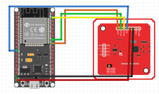
Helo temen-temen anakkendali.com RFID merupakan singkatan dari Radio Frekuensi Identifikasi, yang banyak digunakan pada era digital saat ini seperti alat pembayaran non tunai / e-money, RFID juga digolongkan berdasarkan frekuensinya, ada yang frekuensi rendah, sedang dan tinggi. PN532 setara dengan frekuensi sedang karena memiliki frekuensi 13.56Mhz sama dengan RC522. Kali ini kita akan belajar…
View On WordPress
#Belajar ESP32 IoT RFID#ESP32 PN532 RFID#Menambahkan Kartu EEPROM#Menambahkan Kartu RFID Arduino#Menyimpan Data Kartu RFID EEPROM#RFID Interface ESP32#Tutorial ESP32 PN532 RFID#Tutorial PN532 ESP32
0 notes
Text

ESP32 Starter and Development Kits for Building Bluetooth and WiFi Enabled IoT Devices
The ESP32-WROVER is a powerful small controller with an onboard camera, Wi-Fi and Bluetooth.
This kit helps you learn and use ESP32-WROVER with its components and tutorials.
https://copperhilltech.com/blog/esp32-starter-and-development-kits-for-building-bluetooth-and-wifi-enabled-iot-devices/
0 notes
Text
ESP32: Chat Application (Part 4)
ESP32: Chat Application (Part 4)
Introduction In this part we will add the timestamping functionality, so we can add a timestamp to all the messages sent by users. Although messages are displayed in the UI in sequence, it is useful to have the actual time they were sent. We will be doing the timestamping on the ESP32, to avoid depending on the clients’ clock. To do so, we will configure the system time on the ESP32 using the…
View On WordPress
0 notes
Photo

Cube rover or Cute rover 😉 I designed it last year. 3d printed and opensource. Has node mcu and communicates over wifi. Inspired by 👉 @astrobotictechnology They uploaded some testing footage on their YouTube a while ago please watch it to get an idea how this rover works. I will post a tutorial and demo video soon. I have already shared code ans and files on Github if anyone likes to try it. Cad files: https://grabcad.com/library/cube-rover-by-astrobotic-1 #arduino #3dprinting #robotics #robot #automation #nasa #spacex #cubesat #cuberover #isro #instructables #hobby #education #ai #engineering #electronics #technology #internetofthings #iot #ai #design #engineering #innovation #programming #coding #science #nvidiaembedded #design #diy #esp32 #experiment https://www.instagram.com/saste.jugaad/p/CYY8Dp5PBxM/?utm_medium=tumblr
#arduino#3dprinting#robotics#robot#automation#nasa#spacex#cubesat#cuberover#isro#instructables#hobby#education#ai#engineering#electronics#technology#internetofthings#iot#design#innovation#programming#coding#science#nvidiaembedded#diy#esp32#experiment
1 note
·
View note