#Stepper Motors Drivers and Controllers
Explore tagged Tumblr posts
Visit Tumblr Blog
Explore Tumblr blogs with no restrictions, modern design and the best experience.
Last Seen Tumblr Blogs


Fun Fact
Tumblr Inc. has $15.1M in annual revenue.
Text
https://www.futureelectronics.com/p/semiconductors--analog--drivers--motor-drivers/l298n-stmicroelectronics-5319967
STMicroelectronics, L298N, Drivers Motor Drivers
L298 Series 46 V 2 A Dual Full Bridge Driver Vertical - Multiwatt-15
#STMicroelectronics#L298N#Drivers Motor Drivers#DC motor driver control#circuit#h bridge#4 Phase Bridge Driver#multi MOSFET driver#Bipolar stepper#motor driver chip#Programmable motor driver#brushless motor driver
1 note
·
View note
Text

Spinning up an STSPIN220 motor driver 🌀⚙️
This year, we've worked on adding more stepper drivers to our offerings. We kicked it off with the classic A4988 (https://www.adafruit.com/product/6109), followed up with the fan-favorite TMC2209 (https://www.adafruit.com/product/6121). Now we're circling back to one that's been on our list for a while—the STSPIN220 (https://www.digikey.com/short/f5nq47vq). It's compact, yet powerful, supporting up to 1/256 microstepping and 1A continuous current. Designed for low-voltage steppers, it maxes out at around 10V motor supply. We've included step and direction LEDs, a current adjustment pot that turns the right way, a 47µF bypass cap, and terminal blocks for power and motor control—making it super easy to use.
13 notes
·
View notes
Text
How Do Power, Motor & Robotics Development Tools Drive Innovation in Automation?

Introduction to Modern Development Ecosystems
As the era of intelligent machines, automation, and smart manufacturing continues to advance, Power, Motor & Robotics Development Tools have emerged as essential components in transforming ideas into functioning prototypes and commercial solutions. These tools serve as the backbone for developing precise and reliable control systems used in a wide variety of sectors—from industrial robotics to electric mobility.
With the increasing integration of microcontrollers, sensors, thermal management components, and electronic controllers, development tools offer a modular and practical approach to building sophisticated electronic and electromechanical systems.
What Are Power, Motor & Robotics Development Tools?
Power, Motor & Robotics Development Tools consist of hardware kits, interface boards, and control modules designed to help developers and engineers test, prototype, and deploy automated systems with precision and speed. These tools make it possible to manage current, voltage, mechanical motion, and real-time decision-making in a structured and scalable manner.
By combining essential components such as capacitors, fuses, grips, cables, connectors, and switches, these kits simplify complex engineering challenges, allowing smooth integration with controllers, microprocessors, and sensors.
Exploring the Primary Toolsets in the Field
Power Management Development Tools
Efficient energy management is crucial for ensuring stability and performance in any robotic or motor-driven system.
Development boards supporting AC/DC and DC/DC conversion
Voltage regulators and surge protection circuits for safe energy flow
Thermal sensors and oils to maintain system temperature
Battery management ICs to control charge-discharge cycles
High-efficiency transformers and current monitors
Motor Control Development Tools
Motor control kits are built to manage torque, direction, and speed across a range of motor types.
H-bridge motor drivers for bidirectional motor control
Stepper motor controllers with high-precision movement
Brushless DC motor driver modules with thermal protection
Feedback systems using encoders and optical sensors
PWM-based modules for real-time torque adjustment
Robotics Development Tools
Robotics kits merge both mechanical and electronic domains to simulate and deploy automation.
Preassembled robotic arm platforms with programmable joints
Sensor integration boards for object detection, motion sensing, and environmental monitoring
Wireless modules for IoT connectivity using BLE, Wi-Fi, or RF
Microcontroller development platforms for logic execution
Mounting hardware and cable grips for secure installations
Benefits of Using Professional Development Tools
Advanced development kits offer more than just experimentation—they serve as stepping stones to commercial production. These tools minimize development time and maximize productivity.
Enhance system performance with modular plug-and-play designs
Enable easy integration with laptops, diagnostic tools, and controllers
Reduce design errors through pre-tested circuitry and embedded protection
Facilitate rapid software and firmware updates with compatible microcontrollers
Support debugging with LED indicators, thermal pads, and status feedback
Key Applications Across Industries
The adaptability of Power, Motor & Robotics Development Tools makes them suitable for countless industries and applications where intelligent movement and power efficiency are essential.
Industrial robotics and pick-and-place systems for manufacturing automation
Smart agriculture solutions including automated irrigation and drone control
Automotive design for electric vehicle propulsion and battery systems
Aerospace applications for lightweight, compact control mechanisms
Educational platforms promoting STEM learning with hands-on robotics kits
Essential Components that Enhance Development Kits
While the kits come equipped with core tools, several other components are often required to expand capabilities or tailor the kits to specific use cases.
Sensors: From temperature and light to current and magnetic field detection
Connectors and plugs: For flexible integration of external modules
Switches and contactors: For manual or automatic control
Thermal pads and heatsinks: For preventing overheating during operation
Fuses and circuit protection devices: For safeguarding sensitive electronics
LED displays and character LCD modules: For real-time data visualization
How to Choose the Right Tool for Your Project
With a vast array of kits and tools on the market, selecting the right one depends on your application and environment.
Identify whether your project focuses more on power management, motor control, or full robotic systems
Consider compatibility with popular development environments such as Arduino, STM32, or Raspberry Pi
Check the current and voltage ratings to match your load and motor specifications
Evaluate add-on support for wireless communication and real-time data processing
Ensure the tool includes comprehensive documentation and driver libraries for smooth integration
Why Development Tools Are Crucial for Innovation
At the heart of every advanced automation solution is a well-structured foundation built with accurate control and reliable hardware. Development tools help bridge the gap between conceptualization and realization, giving engineers and makers the freedom to innovate and iterate.
Encourage experimentation with minimal risk
Shorten product development cycles significantly
Simplify complex circuit designs through preconfigured modules
Offer scalability for both low-power and high-power applications
Future Scope and Emerging Trends
The future of development tools is headed toward more AI-integrated, real-time adaptive systems capable of learning and adjusting to their environment. Tools that support machine vision, edge computing, and predictive analytics are gaining traction.
AI-powered motion control for robotics
Integration with cloud platforms for remote diagnostics
Advanced motor drivers with feedback-based optimization
Miniaturized power modules for wearable and mobile robotics
Conclusion: Is It Time to Upgrade Your Engineering Toolkit?
If you're aiming to build smarter, faster, and more energy-efficient systems, Power, Motor & Robotics Development Tools are not optional—they’re essential. These kits support you from idea to implementation, offering the flexibility and performance needed in modern-day innovation.
Whether you're developing a prototype for a high-speed robotic arm or integrating power regulation into a smart grid solution, the right development tools empower you to transform challenges into achievements. Take the leap into next-gen automation and electronics by investing in the tools that make engineering smarter, safer, and more efficient.
#Power Motor & Robotics Development Tools#electronic components#technology#electricalparts#halltronics
0 notes
Text
What are the precautions for using integrated stepper motors?
1.Basic definition of integrated stepper motors Integrated stepper motors are innovative motor products that integrate the driver with the motor body. By embedding the drive circuit directly into the motor, it achieves a high degree of integration between the motor and the driver, simplifies the installation process, reduces maintenance costs, and has significant advantages in space-constrained applications due to its compact structural design.

2.Working principle of integrated stepper motors The working principle of integrated stepper motors is based on the effects of electromagnetic induction and magnetic torque. When the motor receives a pulse signal, the driver controls the rotation angle and speed of the motor according to the frequency and duty cycle of the signal. Specifically, the driver energizes each phase winding of the motor in turn to generate a rotating magnetic field, which in turn generates a magnetic torque in the rotor, causing the rotor to rotate according to a predetermined step angle. By precisely controlling the frequency and number of pulse signals, precise positioning and speed regulation of the motor can be achieved.
3.Main advantages of integrated stepper motors
1.Integrated design: The integrated stepper motor integrates the driver and the motor body, simplifies the system structure, and reduces the difficulty of installation and maintenance. This design reduces external connection points, thereby reducing the failure rate and improving the reliability of the system. 2. High-performance control: The closed-loop control technology is adopted to realize precise control of the motor by real-time feedback of the motor's position and speed information, thereby improving the stability and accuracy of the system. The closed-loop control technology effectively suppresses the step-out phenomenon of the stepper motor and improves the positioning accuracy and repeat positioning accuracy of the system. 3. High-efficiency energy conversion: The design of the motor and the driver is optimized, the power conversion efficiency is improved, the energy consumption is reduced, and it meets the requirements of green environmental protection. This design helps to reduce energy consumption and maintenance costs and improve the overall economic benefits of the equipment. 4. Intelligent operation: It supports a variety of control protocols and interface standards, and can achieve seamless connection with devices such as host computers or PLCs, which is convenient for users to conduct remote monitoring and debugging. This intelligent operation improves the response speed of the system, reduces the complexity of wiring, and makes system integration more convenient and efficient. 5. Enhanced anti-interference ability: By optimizing the electromagnetic compatibility design and adopting advanced signal processing technology, the system's anti-interference ability to electromagnetic interference and environmental noise is enhanced.
6.Reduce operating costs: High-efficiency energy conversion and intelligent operation help reduce energy consumption and maintenance costs and improve the overall economic benefits of the equipment.

4.Precautions for the use of integrated stepper motors
1.Inspection before installation: Before installation, check whether there is mechanical collision or cross interference of other objects around the integrated stepper motor. Choose a solid, flat ground to ensure that the motor is placed stably without shaking or tilting. When connecting the power supply and other auxiliary electrical equipment, pay attention to the correctness of the power supply voltage, frequency and phase sequence.
2.Daily inspection and maintenance: Before daily use, check whether the waveform of the power supply voltage and current of the integrated stepper motor is normal, and whether the various parameters meet the requirements. At the same time, check the mechanical parts of the motor (such as bearings, transmission belts, reducers, etc.) to ensure that all parameters are in normal condition.
3.Operation precautions: Before starting, keep the operating switch in the off state, and set the controller and power switch correctly. When starting, the speed and position should be adjusted gradually to ensure that the motor runs smoothly. During acceleration, try to avoid sudden acceleration or sudden braking of the motor to avoid affecting the life and stability of the motor. During normal operation, if an abnormal condition (such as mechanical shock, power failure, etc.) is encountered, the operation must be stopped immediately and the fault can be eliminated before continuing to use. 4. Maintenance procedures: Keep the equipment clean and tidy, clean the integrated stepper motor regularly, and avoid damage to the machine by dust, grease and particles. It is recommended to perform a comprehensive cleaning and maintenance of the equipment once a month. 5. Working environment requirements: The insulation material standard of the stepper motor is ULB grade, the surface temperature of the motor should be lower than 100°, and the coil temperature rise should be controlled within 80K. High temperature will affect the safety of the insulation system and the stability of the motor. Therefore, special attention should be paid to controlling the temperature rise of the motor when using it in a high temperature environment. This can be achieved by strengthening the heat dissipation conditions or reducing the working current of the motor.
0 notes
Text
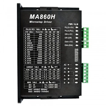
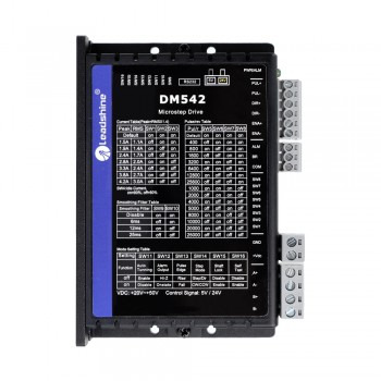
Technical characteristics and maintenance measures of stepper motor drivers
1.Basic definition of stepper motor drivers A stepper motor driver is a device that converts an electrical pulse signal into a drive current signal, which is mainly used to control the angular displacement, speed and position of a stepper motor. The stepper motor driver receives the pulse signal from the controller and converts it into a drive current signal to control the operation of the stepper motor. The speed of the stepper motor is proportional to the pulse frequency, so the speed can be accurately adjusted by controlling the pulse frequency, and the positioning can be accurately achieved by controlling the number of pulses.

2.Working principle of stepper motor driver The main components of the stepper driver include a ring distributor and a power amplifier. The ring distributor is responsible for receiving pulse signals, direction signals and offline signals, and distributing and processing these signals. The power amplifier provides power to the coil of the stepper motor according to the instructions of the ring distributor, thereby controlling the operation of the motor. The stepper motor requires continuous pulse signal input to operate, otherwise it will stop rotating.
3.Technical features of stepper motor drivers
1.High-precision control: The stepper motor driver receives electrical pulse signals and accurately drives the stepper motor to rotate a fixed angle (i.e., the "step angle"), thereby achieving high-precision position control. Each pulse signal corresponds to a specific angle of motor rotation, which enables the stepper motor to achieve high-precision open-loop position control without a feedback system. 2. Advantages of open-loop operation: Stepper motor drivers have significant advantages under open-loop operation. Due to the "step-one-step-stop" characteristics of stepper motors, the driver can operate reliably without position sensor feedback by accurately controlling the pulse signal. This open-loop operation simplifies the system structure and reduces costs. 3. Controllable speed and direction: The stepper motor driver receives pulse signals and direction signals to control the motor's speed, number of steps, and direction of rotation, respectively. The higher the pulse frequency, the faster the motor speed; the direction signal determines whether the motor rotates clockwise or counterclockwise. 4. Low speed and high torque: The stepper motor can provide a large output torque at low speed, which makes it perform well in applications that require low speed and high torque. The driver maintains this advantage by ensuring that the motor coils receive sufficient and accurate current.
5.Programmable current control: Most stepper motor drivers allow users to set the peak current and operating current delivered to the motor, which directly affects the torque and heat output of the motor. Some drivers also support setting the holding current to reduce the heat generated when the motor stops.
6.Microstep drive technology: Modern stepper motor drivers usually provide microstep drive technology, which can achieve finer position control through subdivision control without changing the physical step angle of the motor, further improving the accuracy and performance of the system.

4.Maintenance measures for stepper motor drivers
1.Regular cleaning: Depending on the use environment, regularly clean the surface and interior of the stepper driver to remove dust and impurities. You can use clean gas to blow dust or a soft dry cloth to wipe it gently, but be careful not to use chemical solvents or strong acid and alkali solutions to avoid damage to the driver.
2.Check the connection: Regularly check whether the connection between the stepper driver and the stepper motor and control system is firm to ensure that there is no looseness. If looseness is found, it should be re-fixed in time. 3. Power supply check: Ensure that the power supply of the stepper driver is stable and the voltage meets the equipment standards. If the power supply is found to be unstable or abnormal, the fault should be promptly eliminated or the power supply equipment should be replaced. 4. Temperature control: Pay attention to the operating temperature of the stepper driver and avoid long-term high-temperature operation. You can add heat dissipation equipment such as fans or heat sinks to maintain the normal operating temperature of the driver. 5. Environmental protection: Install the stepper driver in a dry and well-ventilated environment to avoid moisture, excessive dust and other conditions that may adversely affect the equipment. When working in harsh environments, you can consider using dustproof, waterproof covers or shells to improve the protection level of the equipment. 6. Fault handling: If the stepper driver is abnormal or fails, first perform fault diagnosis according to the equipment manual, and repair or replace parts according to the methods provided in the manual. If the problem cannot be solved, you need to contact professional technicians for inspection.
0 notes
Text
A Comprehensive Guide to Instrument Cluster Repair

Your vehicle's instrument cluster—the dashboard display behind your steering wheel—plays a vital role in delivering essential driving information. From speed and RPM to fuel levels and warning lights, the instrument cluster ensures you're always in tune with your vehicle's performance and safety.
With the evolution of technology, the traditional analog displays have been replaced or supplemented by the Automotive Digital Instrument Cluster. These digital systems offer enhanced features, improved aesthetics, and better integration with vehicle electronics. However, like all electronic components, they are not immune to failure.
In this comprehensive guide, we��ll explore the intricacies of instrument cluster repair, from diagnosing common issues to steps for repair and replacement. Whether you're a DIY enthusiast or seeking guidance before visiting a repair shop, this guide will provide the clarity you need.
What is an Instrument Cluster?
The instrument cluster is the collection of displays behind the steering wheel, traditionally composed of analog gauges that show:
Speed (speedometer)
Engine RPM (tachometer)
Fuel levels
Engine temperature
Odometer and trip meter
Warning indicators (battery, oil, seatbelt, check engine)
In today’s vehicles, particularly newer and luxury models, this area has become highly digitized. Instead of analog dials, you’ll find LCD or LED displays powered by embedded software. These modern systems are referred to as the Automotive Digital Instrument Cluster, offering real-time insights, customization options, and seamless communication with other car systems.
Introduction to the Automotive Digital Instrument Cluster
An automotive digital instrument cluster replaces traditional analog gauges with sleek, high-resolution LCD or LED screens. These cutting-edge interfaces go far beyond just showing your speed or fuel level. They serve as a central hub for driving intelligence, bringing together essential data from various vehicle systems in one streamlined view.
Unlike older dashboards with fixed dials and limited functionality, digital clusters are dynamic and fully programmable. They not only provide basic driving information like speed, RPM, fuel level, and engine temperature, but also support advanced capabilities such as:
Turn-by-turn GPS navigation
Real-time traffic and weather alerts
Driver-assist system feedback
Adaptive cruise control status
Media and phone integration
Live engine diagnostics and maintenance alerts
Heads-up display (HUD) compatibility
In vehicles equipped with a fully digital cockpit, the instrument cluster often works in tandem with the infotainment system and central control unit, delivering a unified driving experience.
Common Problems in Instrument Clusters
Instrument clusters, whether traditional analogue or advanced digital, are essential for providing drivers with real-time feedback about their vehicle's performance and safety status. However, over time or due to electrical faults, they can develop various issues. Below are some of the most common problems seen in both analogue and automotive digital instrument cluster systems, along with brief explanations of their causes.
a. Dead Gauges
Gauges like the speedometer, tachometer, oil pressure, or fuel level indicators may stop responding entirely. This is usually caused by a failed stepper motor (in analogue clusters), damaged internal circuits, or faulty sensor input from the vehicle's ECU. In digital clusters, software bugs or a corrupted display controller can also cause gauges to freeze or disappear.
b. Flickering or Dim Display
This issue is prevalent in automotive digital instrument clusters with LCD or LED screens. A flickering display may point to a failing backlight inverter, degraded ribbon cables, or a fluctuating power supply. Inconsistent brightness or a completely dim screen makes the cluster unreadable and dangerous while driving at night.
c. Malfunctioning Warning Lights
The check engine, ABS, airbag, and battery lights are essential for vehicle diagnostics. These lights may illuminate falsely (when no issue exists) or fail to turn on when a real fault occurs. This could be due to a damaged cluster PCB (printed circuit board), short circuits, or corrupted firmware. In digital systems, it may also stem from software errors or CAN-bus miscommunication.
d. Pixelation or Screen Failure
In digital clusters, screen degradation may show up as missing pixels, horizontal/vertical lines, or full blackouts. This could be caused by water damage, physical impact, or a malfunctioning TFT/LCD controller. Over time, wear and tear can also degrade the screen’s contrast and refresh rate, affecting visual clarity.
e. Data Errors
Incorrect readings—such as a fuel gauge showing full when the tank is empty or a speedometer stuck at zero—can occur due to faulty sensors, damaged wiring, or software bugs in the digital processor. In automotive digital instrument clusters, improper calibration or firmware glitches can lead to frequent data inconsistencies, which not only confuse the driver but may also hinder safety system functions.
f. Power Issues
If the entire cluster doesn’t power on, randomly resets, or experiences intermittent operation, it might be due to blown fuses, shorted circuits, or a faulty power control module. In digital systems, software crashes, battery voltage drops, or grounding issues may also cause the display to reboot unexpectedly, especially during engine cranking or cold starts.
g. Communication Faults
Modern vehicles rely heavily on internal communication networks like CAN (Controller Area Network) or LIN Bus. If there’s a disruption in these networks, the Automotive Digital Instrument Cluster may lose connection to essential data sources such as the engine control unit (ECU) or transmission control unit (TCU). This often results in missing information, ghost warnings, or a completely non-functional dashboard.
Accurate Diagnosis Before Instrument Cluster Repair
Before jumping into the repair process, an accurate diagnosis is required. The automotive digital instrument cluster is a sophisticated component that integrates with various vehicle systems, meaning an issue might originate from the cluster itself—or from external sensors, wiring, or the ECU. Misdiagnosing the problem can lead to unnecessary repairs, higher costs, or recurring faults.
Here’s a step-by-step guide to correctly identifying the root cause of the problem:
Step 1: Visual Inspection
Start with a thorough visual check of the instrument cluster and its immediate surroundings. Remove the cluster housing if necessary and inspect:
Connectors: Look for loose plugs, corroded pins, or damaged locking tabs.
Burnt Components: A burnt smell or visible discoloration may indicate a short circuit on the cluster's PCB.
Cracked Solder Joints: Especially around areas where the cluster experiences vibration.
Moisture or Water Damage: This is a common cause of display issues and pixelation in digital clusters.
If the vehicle has recently undergone dashboard work or an aftermarket device was installed (e.g., stereo, alarm, GPS tracker), ensure no harnesses were tampered with or misrouted.
Step 2: Use a Diagnostic Scanner
Plug in an OBD-II (On-Board Diagnostics) scanner to retrieve fault codes related to the cluster, ECU, or communication lines. Many automotive digital instrument clusters are tied into CAN-bus or LIN-bus systems, and scanning will reveal if the cluster is receiving or transmitting incorrect data.
Look for fault codes such as:
U0155 – Lost Communication With Instrument Panel Cluster
B2601/B2603 – Display circuit failure
U0422 – Invalid Data Received From Body Control Module
Advanced scan tools (e.g., Autel, Launch, Bosch, Snap-On) may also let you run live tests on the cluster's display, gauge response, and warning lights.
Step 3: Electrical Testing
Use a digital multimeter to perform voltage, continuity, and ground checks:
Battery Voltage: Ensure the cluster is receiving the correct voltage from the fuse box. A voltage drop can cause flickering or a complete power-off.
Ground Connection: A poor ground can lead to erratic behavior, dim lights, or failure to boot.
Continuity Tests: Check the wiring harness from the cluster to the ECU and sensors for breaks, corrosion, or shorts.
Backlight Circuit Check: If backlights are dim or flickering, test for stable power supply to the LED driver circuits.
Testing the circuit at different ignition stages (ACC, ON, CRANK) can help determine if a voltage drop or power surge is causing intermittent faults.
Step 4: Observe Symptom Patterns
Pay close attention to when and how the problem manifests. Tracking symptom patterns will help narrow down the cause:
During Ignition: Flickering or rebooting during engine start may indicate weak power delivery or cluster capacitor failure.
After Hitting a Bump: Suggests a loose connector, dry solder joint, or vibration-sensitive failure.
Intermittent Glitches: Points toward failing internal components, memory corruption, or thermal sensitivity.
Only in Cold/Hot Weather: Might indicate temperature-sensitive components, particularly in LCD screens or solder joints.
Specific Driving Modes: If issues only arise in Eco/Sport modes, it could involve software conflicts or CAN-bus messaging faults.
This observational data will be especially valuable if you need to consult a technician or plan for a deeper teardown.
Step 5: Test with a Known Good Unit
If available, swap out the suspected cluster with a working, compatible instrument cluster. This is often the most direct way to isolate whether the fault lies within the unit itself or elsewhere in the vehicle system.
Important Considerations:
Ensure the test cluster matches the vehicle make, model, and trim level to prevent communication mismatches.
Some automotive digital instrument clusters require VIN-coding or immobilizer sync, so you may need dealer-level diagnostic tools (e.g., Techstream, VCDS, Forscan).
If the symptoms disappear after the swap, the original cluster is faulty. If they remain, focus on sensors, wiring, or control modules.
Repair vs. Replacement: What Should You Choose?
Depending on the issue, you may consider repairing or replacing your cluster. Here’s a breakdown:
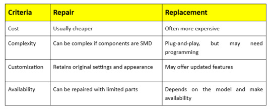
For rare or luxury vehicles with unique automotive digital instrument clusters, repair is often the only feasible option.
Step-by-Step Instrument Cluster Repair Process
Repairing an instrument cluster, especially a modern automotive digital instrument cluster, requires precision, attention to detail, and a basic understanding of electronics. Here’s a detailed breakdown of the general repair process:
Step 1: Disconnect the Battery
Safety always comes first. Before touching any part of your vehicle’s electrical system, disconnect the car battery, preferably starting with the negative terminal. This eliminates the risk of short circuits, electrical shocks, or accidentally triggering airbags when handling digital dashboard components. Let the vehicle sit for a few minutes after disconnecting to allow any residual charge to dissipate from the capacitors.
Step 2: Remove the Instrument Cluster
Carefully dismantle the dashboard.
Remove surrounding panels using a trim removal tool to avoid damaging plastic clips.
Unscrew mounting bolts holding the cluster in place—usually Torx or Phillips screws.
Gently pull out the cluster, being mindful of its size and shape.
Disconnect the wiring harnesses one by one, ensuring you don’t bend or damage the pins. Some clusters also have locking tabs on connectors that need to be depressed before removal.
Marking connector positions or photographing the setup beforehand helps during reinstallation
Step 3: Open the Cluster
Once removed, place the cluster on a clean, static-free surface. Use an anti-static wrist strap and proper tools to open the casing, which often includes plastic clips or small screws.
Take your time here—modern clusters, especially digital ones, use delicate PCB assemblies and ribbon cables that can be damaged easily. If the cluster is sealed or potted (common in some digital models), you may need specialized tools or heating methods to soften the adhesive.
Step 4: Identify Faulty Components
Visually inspect the internal components:
Look for physical damage like burnt resistors, leaking capacitors, or blackened areas.
Check solder joints, especially on high-vibration areas like connector pins and voltage regulators—cracks can cause intermittent faults.
In automotive digital instrument clusters, check the LCD driver circuits, processor ICs, and signal transceivers.
Use a magnifying glass or microscope if needed to spot fine cracks or corrosion, particularly in high-humidity environments.
If you’re unsure, a thermal camera or oscilloscope can help locate malfunctioning components.
Step 5: Repair or Replace Components
Use a fine-tip soldering iron or hot air tool to remove and replace faulty capacitors, resistors, or ICs. For LCD issues in automotive digital instrument clusters, replace the screen or driver board carefully, handling ribbon cables with caution. After repairs, clean the PCB with isopropyl alcohol to remove solder residue and ensure solid, clean solder joints.
Step 6: Test the Cluster
Before reinstalling, test the cluster using a bench simulator if available to verify gauge movements, display clarity, and warning light functionality. If no simulator is available, temporarily reconnect the cluster in the vehicle to check for errors or abnormal behavior during startup and operation.
Step 7: Reinstall and Reconnect
Reconnect all wiring harnesses securely, mount the cluster properly, and replace any dashboard panels. Reconnect the battery, start the car, and observe the instrument cluster for proper startup, gauge sweep, and accurate readings. Take a short test drive to confirm everything works correctly.
7. Tools Required for Instrument Cluster Repair
Screwdrivers (Phillips and Torx)
Soldering iron and solder
Multimeter
Anti-static mat and wrist strap
OBD-II scanner
Digital cluster simulator (optional)
Magnifying glass or microscope (for PCB inspection)
Hot air rework station (for surface-mounted devices)
Preventative Maintenance Tips
While electronic failures in instrument clusters can sometimes be unavoidable, there are several proactive steps you can take to minimize the risk and prolong the life of your automotive digital instrument cluster:
a. Avoid Electrical Surges
Install a surge protector or voltage stabilizer to shield your vehicle’s electrical system from sudden voltage spikes. Regularly maintain your battery’s health by checking terminals and charging levels to prevent unexpected surges that can damage sensitive instrument cluster components.
b. Protect From Moisture
Keep your vehicle’s interior dry by promptly fixing leaks and using moisture absorbers if necessary. Moisture can cause corrosion on circuit boards and connectors, leading to malfunction or failure of the instrument cluster’s delicate electronic parts over time.
c. Gentle Driving
Drive carefully over rough terrain, avoiding sharp bumps and potholes whenever possible. Harsh jolts and vibrations can loosen or damage internal cluster components, especially fragile solder joints and delicate sensors, which may cause intermittent faults or complete failure.
d. Software Updates
Keep the Automotive Digital Instrument Cluster’s firmware up to date by following manufacturer recommendations or visiting authorized service centers. Software updates often include bug fixes, improved system stability, and new features that enhance cluster performance and reliability.
Professional Repair Services: What to Expect
If DIY repair isn’t your style, professional services offer precision and warranty-backed repairs.
What They Offer:
Detailed diagnostics
Chip-level repairs
Screen and LED replacements
Firmware updates
Odometer correction (legal limitations apply)
Choosing a Repair Shop:
Look for specialization in digital clusters
Check online reviews
Ask for warranty terms
Ensure compliance with legal standards for odometer readings
Cost of Instrument Cluster Repairs
Costs vary depending on the vehicle make, model, and the type of cluster (analog vs. digital).
Estimated Costs:
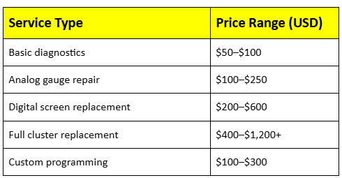
For high-end vehicles with a sophisticated Automotive Digital Instrument Cluster, prices can climb significantly.
Conclusion
Your instrument cluster is more than just a display—it’s a critical part of your vehicle’s communication system. It provides you with essential information such as speed, fuel levels, engine temperature, and warning indicators that help ensure your safety on the road. As technology advances, the automotive digital instrument cluster becomes increasingly central to the driving experience, offering customisable interfaces, navigation, and integration with driver-assist systems. However, with this increased complexity comes a higher chance of malfunction or failure, which can affect your ability to monitor vital vehicle functions accurately.
Understanding how to diagnose, repair, or replace your cluster empowers you to make informed decisions, whether you’re tackling the repair yourself or working with a professional technician. By staying proactive—performing regular maintenance, updating software, and promptly addressing warning signs—you can ensure your instrument cluster remains reliable and accurate for years to come. This not only enhances driving safety but also helps preserve your vehicle’s value and performance over time.
#InstrumentClusterRepair#CarDashboardRepair#AutomotiveRepairGuide#DashboardDisplay#CarTechFix#DigitalInstrumentCluster#VehicleDiagnostics#AutoTechTips#InstrumentPanelFix#DIYCarRepair#AutomotiveDigitalInstrumentCluster#ClusterRepairTips#CarMaintenance#AutomotiveTechnology#FixYourCar
0 notes
Text
Automation Boom Fuels Growth in Motion Control Drive Market to $8.4 Billion by 2031
The global motion control drive market encompassing servo drives, stepper drives, and variable frequency (VFD) drives was valued at US$ 4.9 billion in 2022. Driven by the surge in automation, robotics, and precision motor control requirements, the market is forecast to expand at a compound annual growth rate (CAGR) of 6.2% from 2023 through 2031, reaching US$ 8.4 billion by the end of the forecast period. Motion control drives regulate voltage, current, speed, and position of motors in applications ranging from CNC machining and semiconductor manufacturing to packaging, automotive, and materials handling.
Market Drivers & Trends
Automation & Industry 4.0 Adoption: Increasing deployment of automation across manufacturing verticals is fundamentally reshaping production lines. Motion control drives, which ensure precise and synchronized movements in robotic arms, conveyor systems, and automated assembly lines, are integral to Industry 4.0 ecosystems.
Integration of IoT & AI: Smart factories require drives that can self-diagnose, self-tune, and communicate performance data. The integration of Internet of Things (IoT) connectivity and artificial intelligence (AI) within drives enables predictive maintenance, reduced downtime, and optimized energy usage.
Compact & Modular Designs: Space constraints and the need for flexible machine layouts have spurred demand for compact drive systems. Solutions such as Bosch Rexroth’s ctrlX DRIVE and Rockwell Automation’s ArmorKinetix series offer modular, scalable form factors that simplify installation and support mobile and portable applications.
Energy Efficiency & Sustainability: With global pressures to reduce energy consumption and carbon footprints, manufacturers are adopting high-efficiency drives that minimize losses and recover regenerative energy—key considerations for sectors like automotive, aerospace, and materials handling.
Latest Market Trends
Self‑Tuning Servo Drives: Advanced digital servo drives can now autonomously adjust motor, drive, and feedback parameters to optimize performance. These self‑tuning capabilities reduce the need for manual calibration of control loops and enhance overall system robustness.
Multi‑Axis Synchronization: As multi-axis robots and gantry systems grow more prevalent, drives capable of precise, coordinated control across several axes are in high demand. Enhanced synchronization features enable smoother motion profiles and greater throughput.
Embedded Safety Functions: Functional safety is increasingly embedded into drive platforms, offering integrated safety monitoring, safe torque off (STO), and safe motion functions. This reduces the footprint and complexity of additional safety components in automated machinery.
Cloud‑Based Drive Management: Vendors are launching cloud‑connected platforms for remote configuration, firmware updates, and performance monitoring, enabling centralized management of distributed drive fleets.
Key Players and Industry Leaders
The motion control drive market remains fragmented, with a diverse set of global and regional players competing on innovation, customization, and service:
ABB Ltd.
Siemens AG
Rockwell Automation Inc.
Bosch Rexroth
Mitsubishi Electric Corporation
Schneider Electric SE
Delta Electronics, Inc.
OMRON Corporation
YASKAWA Electric Corporation
Toshiba Corporation
Allied Motion, Inc.
Advanced Micro Controls, Inc.
Fuji Electric Co., Ltd.
Emerson Electric Co.
HIWIN Corporation
Nidec Motor Corporation
These companies remain at the forefront through continuous R&D investment, strategic acquisitions, and partnerships to expand product portfolios and regional footprints.
Unlock crucial data and key findings from our Report in this sample - https://www.transparencymarketresearch.com/sample/sample.php?flag=S&rep_id=52011
Recent Developments
August 2023: Kollmorgen expanded its AKD2G servo drive portfolio, introducing higher amperage models with enhanced safety features and SD card backup, plus a graphical display for simplified multi-axis setup.
May 2023: ABB completed the acquisition of Siemens’ low-voltage NEMA motor business, strengthening its portfolio of integrated motor‑and‑drive solutions for North American markets.
2022: WEG acquired Gefran’s Motion Control Business Unit, gaining full ownership of variable frequency drives, DC converters, and specialized servo drives to bolster its automation offerings.
June 2021: Bosch Rexroth launched its ctrlX DRIVE system—a compact, scalable drive platform designed for easy integration into mobile and space-optimized machinery.
August 2023: Rockwell Automation unveiled Allen‑Bradley ArmorKinetix servo drives that mount directly to motors, simplifying machine assembly and improving performance flexibility.
Market Opportunities
Emerging Economies: Rapid industrialization in Southeast Asia, Latin America, and parts of Eastern Europe is driving demand for mid‑range automation solutions—an opportunity for manufacturers to introduce cost‑effective drive systems.
Smart Manufacturing Upgrades: Legacy factories undergoing digital transformation need retrofit‑friendly drive solutions with IoT connectivity and embedded safety, presenting a sizable aftermarket for system integrators.
Sustainable Energy Projects: Renewable energy installations, including solar trackers and wind turbine pitch control systems, require robust drives optimized for harsh environments and long service intervals.
Customized Solutions: Increasingly, end‑users demand turnkey, application‑specific drive packages—bundling drives with built‑in safety, condition monitoring, and domain‑specific software tools.
Future Outlook
Over the next decade, the motion control drive market will continue to evolve along several axes:
Digitalization: Drives will become central nodes in digital value chains, sending real‑time telemetry to cloud‑based analytics platforms for AI‑driven optimization.
Integration: We can expect tighter integration of drives with higher‑level controllers—blurring the lines between PLC, motion controller, and drive in next‑generation architectures.
Safety & Compliance: As regulatory standards evolve, drives will natively support functional safety protocols (e.g., TÜV‑certified safety functions) to simplify machine approvals.
Miniaturization: Advances in power electronics will permit further size reduction, enabling distributed, embedded drive solutions in compact robotics and wearable exoskeletons.
Buy this Premium Research Report and access vital insights and analysis – https://www.transparencymarketresearch.com/checkout.php?rep_id=52011<ype=S
Market Segmentation
By Type: AC Drives, DC Drives
By Product Type: Servo Drives, Stepper Drives, VFD Drives
By Axis: Single‑Axis, Multi‑Axis
By Precision: Very High Precision, High Precision, Standard
By End‑Use: Semiconductor & Electronics, Food & Beverage, Aerospace & Defense, Automotive, Paper & Printing, Pharmaceuticals, Metals & Machinery, Others
Regional Insights
Asia Pacific: Held the largest share in 2022, driven by heavy investments in manufacturing automation and robotics in China, Japan, South Korea, and India. China’s shrinking labor force and rising robotics installations (81,600 units in 2021, up 30%) underpin strong demand.
North America: Growth fueled by automotive electrification, semiconductor fab expansions, and food & beverage upgrades—coupled with strategic investments by ABB and Rockwell.
Europe: Focus on Industry 4.0 and sustainability is driving adoption of energy‑efficient drives, particularly in Germany, Italy, and the U.K.
Latin America & MEA: Emerging manufacturing hubs in Brazil, Mexico, and UAE present opportunities for mid‑tier drive manufacturers.
Why Buy This Report?
Comprehensive Analysis: Detailed market segmentation, quantitative forecasts (US$ Bn & million units), and historical data spanning 2017–2022.
Strategic Insights: In‑depth qualitative analysis, including drivers, restraints, opportunities, key trends, Porter’s Five Forces, value chain, and competitive landscape.
Company Profiles: Thorough profiles of leading players—covering corporate strategy, financials, product portfolios, M&A, and recent developments.
Decision‑Making Support: Actionable recommendations for new market entrants, technology licensors, system integrators, and investors seeking to capitalize on emerging applications and regional growth hotspots.
Multi‑Format Delivery: Available in PDF and Excel formats, facilitating integration with internal reporting and strategic planning processes.
Explore Latest Research Reports by Transparency Market Research: SMT Equipment Market: https://www.transparencymarketresearch.com/smt-equipment-market.html
Motion Control Drive Market: https://www.transparencymarketresearch.com/motion-control-drive-market.html
3D Printing Medical Devices Market: https://www.transparencymarketresearch.com/3d-printing-medical-devices-market.html
Nano Positioning Systems Market: https://www.transparencymarketresearch.com/nano-positioning-systems-market.html
About Transparency Market Research Transparency Market Research, a global market research company registered at Wilmington, Delaware, United States, provides custom research and consulting services. Our exclusive blend of quantitative forecasting and trends analysis provides forward-looking insights for thousands of decision makers. Our experienced team of Analysts, Researchers, and Consultants use proprietary data sources and various tools & techniques to gather and analyses information. Our data repository is continuously updated and revised by a team of research experts, so that it always reflects the latest trends and information. With a broad research and analysis capability, Transparency Market Research employs rigorous primary and secondary research techniques in developing distinctive data sets and research material for business reports. Contact: Transparency Market Research Inc. CORPORATE HEADQUARTER DOWNTOWN, 1000 N. West Street, Suite 1200, Wilmington, Delaware 19801 USA Tel: +1-518-618-1030 USA - Canada Toll Free: 866-552-3453 Website: https://www.transparencymarketresearch.com Email: [email protected]
0 notes
Text
Stepper Motors in Cars: The Unsung Heroes Behind Smooth Engine Performance
Have you ever wondered what keeps your car’s engine idling smoothly, manages airflow precisely, or ensures your acceleration feels just right? The answer might surprise you — it’s a stepper motor.
While small and often overlooked, stepper motors are critical to modern automotive systems. From controlling the throttle to regulating idle speed, these components operate behind the scenes to keep your engine efficient and your driving experience seamless.
What Exactly Is a Stepper Motor?
A stepper motor is a brushless electric motor that moves in precise, discrete steps. Each electrical pulse sent to the motor turns it slightly — often 1.8 or 0.9 degrees per step. This design allows for incredibly accurate positioning without needing feedback sensors. That’s why they’re widely used not just in cars, but also in 3D printers, CNC machines, and robotics.
Two Main Types of Stepper Motors in Automotive Use
Understanding stepper motors begins with recognizing their two core types:
Permanent Magnet (PM): Uses a rotor with permanent magnets. These motors offer high torque and precision, ideal for controlling critical systems like throttle position.
Variable Reluctance (VR): A simpler design without permanent magnets, generally cheaper and better for high-speed applications.
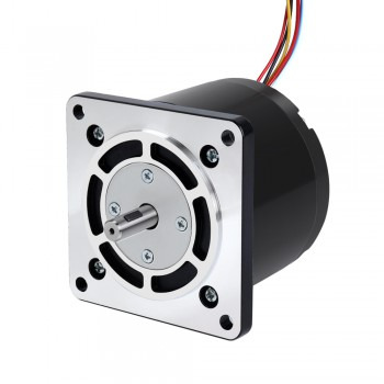
Inside a Stepper Motor: Key Components
Every stepper motor is made up of:
Rotor: The rotating core, often magnetized
Stator: The stationary housing with coils
Windings: Energized in a specific order to move the rotor
Shaft, bearings, and housing: Ensure smooth, reliable rotation
Electrical connectors: Link the motor to the vehicle’s ECU
Together, these parts enable the motor to deliver pinpoint control over movement.
Why Stepper Motors Matter in Your Car
In modern vehicles, stepper motors handle several essential tasks:
✅ Idle Speed Control (ISC)
Regulates air intake when the engine is idle, preventing stalls and maintaining fuel efficiency.
✅ Electronic Throttle Control (ETC)
Replaces the traditional throttle cable, providing smoother acceleration and better fuel economy.
✅ HVAC Airflow Management
Controls air dampers in your car’s ventilation system for accurate climate control.
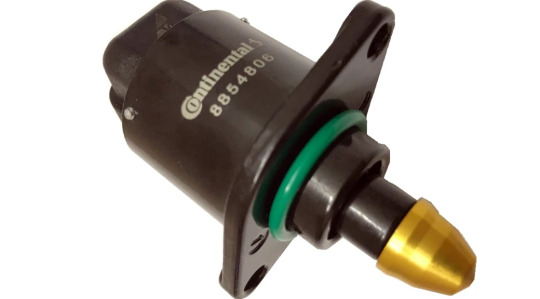
Where Are Stepper Motors Located?
Typically found near or within the throttle body or intake manifold, stepper motors are designed for easy access and quick replacement.
Manual vs. Automated Stepper Motors
Some early or simplified designs use manual stepper motors, operated through basic circuits or switches — great for educational projects or legacy devices. However, modern vehicles rely on electronically controlled versions paired with stepper motor drivers for seamless automation.
Stepper Motor Drivers: The Hidden Brains
A stepper motor needs a driver to function. These drivers convert electrical pulses from the Engine Control Unit (ECU) into specific currents for the motor windings. Advanced drivers use microstepping for ultra-smooth movement and reduced noise.
Step-by-Step: How a Stepper Motor Works in a Car
The ECU analyzes RPM and engine load
Sends control pulses to the stepper motor driver
The driver activates stator windings in sequence
The rotor rotates step by step
This precise control loop is essential to smooth engine operation.
Signs Your Stepper Motor Might Be Failing
Here’s what to watch for:
Rough idling or RPM fluctuations
Check Engine Light with codes P0505–P0508
Increased fuel consumption (up to 15%)
Sudden stalling during deceleration
Why Do Stepper Motors Fail?
Common causes include:
Wrong driver settings → Overheating or damage
Loose wiring or poor connectors
Excessive engine heat or poor ventilation
Mechanical wear in bearings or shaft
Environmental exposure (dust, moisture)
Low-quality parts
Lack of preventive maintenance
Troubleshooting a Faulty Stepper Motor
Diagnosing issues usually involves:
Checking wiring and voltage with a multimeter
Testing resistance (normal range: 30–80 ohms)
Ensuring the driver sends correct pulse signals
Running test cycles with diagnostic tools
Listening for unusual noise or vibration
When Should You Replace a Stepper Motor?
Replace the motor if you notice:
Out-of-range resistance readings
Abnormal friction or binding in the shaft
Persistent error codes or failed test cycles
Do Stepper Motors Need Lubrication?
Generally no — these motors are sealed and maintenance-free. But if contamination occurs, use automotive-grade contact cleaner or silicone lubricant to clean the shaft (never apply oil to the windings).
How Much Do Stepper Motors Cost?
Prices (as of winter 2024 in Iran): 500,000 to 2,000,000 Tomans, depending on:
Car brand (OEM vs. aftermarket)
Motor specs (full-step vs. microstep)
Presence of feedback sensors
Choose a motor compatible with your vehicle model and ECU system.
Thinking About Removing It? Think Again.
Removing the stepper motor without ECU reprogramming can cause:
Idle speeds over 1500 RPM
Engine management system errors
Emissions violations (Euro 4+)
Legal trouble in regulated regions
Does It Affect Acceleration?
Not directly, but malfunctioning stepper motors can cause:
Delayed throttle response
Unstable air-fuel ratios
Reduced EGR system performance
Final Thoughts: Small Part, Big Impact
Despite their size, stepper motors are fundamental to engine stability, throttle accuracy, and fuel efficiency. Understanding how they work — and how to maintain or replace them — is vital for both DIY car enthusiasts and professional technicians.
A healthy stepper motor means a smoother drive, better fuel economy, and fewer unexpected repairs down the road.
0 notes
Text
5 Common CNC Router Controller Issues and How to Fix Them

In the world of modern manufacturing, CNC routers are indispensable for achieving precision and efficiency. However, even the most advanced machines are vulnerable to technical glitches—particularly with their controllers. A CNC router controller is essentially the command center that translates software instructions into physical movement. When something goes wrong here, it can bring your entire operation to a halt.
This article dives deep into the five most common CNC router controller issues, how to troubleshoot them effectively, and what you can do to prevent them in the future. Whether you're running a small shop or managing a high-volume production line, these insights will help keep your machine in top shape.
1. Controller Won’t Power On
You hit the switch—and nothing. No lights, no motion, no signs of life.
Why It Happens:
Blown fuses or breakers.
Loose or disconnected power cables.
Malfunctioning power supply unit (PSU).
Incorrect input voltage or surge damage.
How to Fix It:
Check and replace any blown fuses.
Make sure power cords are firmly connected and not frayed.
Test the PSU with a multimeter to verify correct output voltage.
Use a voltage regulator or surge protector to prevent future damage.
Pro Tip: Label your power supply connections clearly during setup. It makes troubleshooting faster and easier.
2. Freezing or Crashing During Jobs
Midway through a cut, your router suddenly locks up. Job ruined, material wasted.
Why It Happens:
Controller overheating due to poor airflow.
Bugs or incompatibility in the firmware/software.
Memory overload from excessive G-code complexity.
EMI (electromagnetic interference) or loose data connections.
How to Fix It:
Keep the controller clean and properly ventilated.
Ensure all software and firmware are updated to stable versions.
Break up large files into smaller toolpaths.
Use shielded cables and ensure proper grounding to eliminate EMI.
Maintenance Hack: Consider using CNC Control Retrofits that come with improved cooling and processing power to reduce these occurrences significantly.
3. Axis Movement Not Working
If your CNC router won’t move along the X, Y, or Z axis, you’re essentially grounded.
Why It Happens:
Stepper driver failure.
Motor or cable disconnects.
Faulty G-code or coordinate settings.
Loose or stripped motor couplings.
How to Fix It:
Double-check driver and motor connections.
Test drivers individually by swapping them between axes.
Inspect and fix any loose mechanical parts.
Review your CAM setup to ensure proper motion commands are being sent.
Upgrade Tip: If your machine frequently suffers from axis issues, consider CNC Control Retrofits that upgrade your stepper systems to more reliable and powerful servo motors.
4. Controller Doesn’t Connect to Computer
You plug in the USB cable and nothing happens—no connection, no control.
Why It Happens:
Outdated or missing drivers.
Cheap or damaged USB cables.
Wrong COM port selected in software.
Firmware and software version mismatch.
How to Fix It:
Install the correct drivers (often CH340 or FTDI).
Replace USB cable with a short, shielded one.
In your control software, manually select the correct COM port.
Verify the firmware on your controller is compatible with your software version.
Pro Note: Avoid USB hubs. Connect directly to your PC's port whenever possible.
5. Spindle Won’t Start or Has Speed Issues
Spindle problems can cause major setbacks—especially when cuts rely on consistent speeds.
Why It Happens:
No PWM or analog control signal.
Misconfigured spindle driver or VFD.
Incorrect G-code spindle commands (e.g., M3, S1000).
Motor overload or faulty wiring.
How to Fix It:
Ensure all spindle control wiring is secure and accurate.
Verify VFD settings align with your spindle motor specs.
Use test commands (M3 S1000, M5) to isolate the problem.
Test spindle motor directly to confirm it’s functional.
Expert Insight: CNC Control Retrofits often include improved spindle control systems, allowing for smoother and more reliable speed regulation across various materials.
Bonus: Preventing CNC Controller Problems
Fixing problems is good. Preventing them is better. Here’s how:
Regular Cleaning: Dust buildup is the silent killer of electronics.
Firmware Updates: Always run the most stable versions—not betas.
Cable Management: Keep power and signal wires separated.
Surge Protection: Always use voltage regulators or UPS systems.
Monthly Checklist: Schedule a 15-minute inspection every month to check connections, clean filters, and back up your machine settings.
Conclusion
CNC routers are amazing tools—but only when the controller is functioning flawlessly. Whether you're dealing with power issues, motion problems, or connectivity failures, the key is understanding what’s going wrong and how to fix it efficiently.
As we've seen, many common problems can be traced back to simple issues like loose wires or outdated software. But if you're constantly struggling with performance or compatibility, it's worth considering CNC Control Retrofits to upgrade aging systems with modern, more reliable hardware.
By applying the strategies in this guide, you'll not only be ready to fix issues quickly, but you'll also be in a strong position to prevent future downtime, maximize efficiency, and get the most out of your CNC investment.
1 note
·
View note
Text
RBA Optisync Private Limited is a leading supplier of multi-axis stepper drive control systems, based in Gujarat, India. Our advanced stepper drivers, including the R Series, are designed with 32-bit DSP platforms and micro-stepping technology, ensuring precise motion control and smooth operation. These drivers support various control methods, such as pulse and switch control, and are compatible with a wide range of motor sizes, making them suitable for diverse industrial applications. With features like auto-tuning, optimized anti-interference ability, and robust hardware design, RBA Optisync's multi-axis stepper drives offer reliable performance in demanding environments. Our commitment to quality and innovation has made them a trusted partner for industries seeking efficient and customizable motion control solutions.
#Multi-Axis Stepper Drive Control#Multi-Axis Stepper Drive#Multi-Axis Stepper Drive Control Supplier#Multi-Axis Stepper Drive Control in India#Multi-Axis Stepper Drive Control in Gujarat
0 notes
Text
The Raspberry Pi 500 Desktop and Monitor debut, alongside a 512GB Raspberry Pi NVMe SSD for ample storage. A snap-on enclosure for the USB/DC/Solar Lithium Charger, LED filaments in fun shapes, and the A4988 Stepper Motor Driver for motor control https://adafruit.com/new
#adafruit#aht20#humiditysensor#temperaturesensor#stemmaqt#qwiic#usbcable#usbextension#panelmount#raspberrypi#raspberrypi500#nvme#ssd#highcapacitystorage#snaponenclosure#solarcharger#ledfilament#steppermotordriver#motorcontrol#makerprojects#electronics#iot#3dprinting#diytech#techinnovation#robotics#opensourcehardware#ledlighting#techgadgets#electronicsengineering
28 notes
·
View notes
Text
#NOVOSENSE#automotive#motor#communication#reliability#powertrain control.#powerelectronics#powermanagement#powersemiconductor
0 notes
Text
Introduction to the main faults of variable reluctance stepper motors
1.Working principle of variable reluctance stepper motors The working principle of variable reluctance stepper motors is mainly based on electromagnetic induction and magnetic field changes. Specifically, when an electrical pulse signal is given, the corresponding coil will be energized to generate a magnetic field. This magnetic field interacts with the permanent magnet or electromagnet inside the motor to make the motor rotor rotate a step angle in a specific direction. By continuously giving multiple electrical pulse signals and controlling the sequence and time interval of these signals, continuous rotation and precise positioning of the motor can be achieved.
2.The main structure of variable reluctance stepper motors
1.The stator is a fixed part, mainly composed of a set of electromagnet windings, which is used to generate a magnetic field. The design of the stator requires extremely high stability and strength to ensure the precise control of the motor.
2.The rotor is the rotating part of the stepper motor, consisting of a set of steel materials or iron cores. When the magnetic field of the stator changes, the rotor will rotate with the change of the magnetic field.
3.The excitation system controls the current and magnetic field of the stator winding and is the commander of the motor. It is responsible for managing the sequence and power-on time of the winding current to ensure that the motor can rotate in the expected steps.
4.The control circuit is responsible for generating and controlling the current signal to ensure that the excitation system can work in the predetermined order and timing. The design and implementation of the control circuit are crucial to the performance and accuracy of the motor.
3.Control methods of variable reluctance stepper motors
1.Open-loop control: This is the most basic and simplest control method for stepper motors. In this control method, the controller sends a series of pulse signals to the driver, and each pulse causes the motor to rotate a fixed angle.
2.Closed-loop control: In order to improve the accuracy and stability of control, closed-loop control can be used. Closed-loop control monitors the position and speed of the motor in real time through a feedback mechanism, and adjusts the control signal based on the feedback results. Common closed-loop controls include position closed-loop and speed closed-loop.
3.Vector control: Vector control is an advanced control strategy that achieves efficient energy utilization and improved dynamic performance by precisely controlling the magnetic field and torque of the motor. Vector control can obtain the rotor position and current data of the motor through the magnetic encoder and phase current sampling circuit, and then achieve precise control through the closed-loop control algorithm (such as position loop, speed loop and current loop) inside the software.
4.Angle control method (APC): This method adjusts the current waveform by controlling the opening angle and the closing angle, thereby affecting the output torque and speed of the motor. The advantage of angle control is that the torque adjustment range is large and suitable for high-speed operation, but not suitable for low-speed conditions.
5.Current chopping control method (CCC): In this method, the current peak is adjusted by controlling the chopping current limit to control the torque and speed of the motor. This method is suitable for occasions where fine adjustment of motor performance is required.

4.Main faults of variable reluctance stepper motors
1.Heating problem: Variable reluctance stepper motors generate a lot of heat when running at high speed, and their heat dissipation conditions are poor, which makes the internal temperature of the motor easy to rise. If the temperature is too high, it may cause the insulation of the motor winding to burn out, thereby affecting the service life of the motor. 2. Failure of the reluctance synchronization mechanism: Since the variable reluctance stepper motor adopts a complex reluctance synchronization mechanism, there are many parts and it is difficult to process. Once a part fails, the entire mechanism may need to be disassembled and repaired, which increases the difficulty and cost of maintenance. In addition, the reluctance synchronization mechanism is also prone to wear. 3. Difficulty in starting: The variable reluctance stepper motor does not have the characteristics of self-starting, and requires external auxiliary equipment to start, which increases the difficulty and cost of motor starting. 4. Bearing problem: The bearing is an important part of the motor. Long-term operation may cause wear or damage, abnormal vibration and noise. Regular inspection and maintenance of bearings are the key to preventing such failures. 5. Electrical failure: Including low stator winding voltage, open stator winding or circuit problems, broken starter cage or poor contact at the joint. These faults may cause the motor to fail to operate or start normally. 6. Demagnetization problem: For permanent magnet synchronous motors, there is also a risk of demagnetization. Demagnetization may cause the motor to degrade in performance or even fail to work properly. Demagnetization can be determined by measuring the difficulty of the motor's rotor rotation. 7. Excessive noise and vibration: This may be caused by excessive transmission gear clearance, excessive load, incorrect wiring, etc. 8. Step loss and step failure: This may be caused by excessive load, unstable power supply voltage, drive circuit problems, etc.
0 notes
Text
Cnc Router Machine Wood Automatic Engraving Carving Machine Trapezoidal Screw Rack Diy Cnc 3 Axis Cnc Router Kit
Title small size computer controller wood automatic engraving carving machine trapezoidal screw rack diy cnc 3 axis cnc router kit Stepper Motor Product Categories Topsale products Hybrid Stepper Motor Closed loop stepper motor Cnc Carving Machine Planetary gearbox Stepper motor driver Stepper motor controller Motor fittings DC Brushless motor Servo motor Products Details MOQ 2…
0 notes
Text
Main functions and maintenance methods of stepper motor drivers
1.Introduction to the working principle of stepper motor drivers The stepper motor driver is an actuator that converts electrical pulses into angular displacement. The stepper motor driver accurately controls the number of steps, speed and direction of the stepper motor by receiving pulse signals from the control system. The working principle of the stepper motor is to convert the electrical pulse signal into angular displacement, and control the angular displacement by controlling the number of pulses, thereby achieving precise control of the motor position.
2.Main components of stepper motor drivers 1.Microprocessor: As the core component of the stepper motor driver, it is responsible for receiving input signals, processing control algorithms and outputting control signals. Microprocessors usually use high-performance, low-power single-chip microcomputers or DSP chips, with rich peripheral interfaces and powerful processing capabilities. 2.Power amplifier: Responsible for amplifying the control signal output by the microprocessor into the driving current required by the motor. The power amplifier usually uses switching power supply technology, with the characteristics of high efficiency, high power density and low noise, and has over-current, over-voltage, short-circuit and other protection functions to ensure the safe and stable operation of the motor. 3.Drive circuit: The bridge connecting the microprocessor and the power amplifier is responsible for converting the control signal into a signal that the motor can recognize.
3.The main functions of the stepper motor driver 1.Pulse distribution: The stepper motor driver controls the movement of the motor by receiving the control signal and converting it into the drive signal of the motor. Specifically, the ring distributor in the driver receives the pulse signal, direction signal and offline signal, and accurately controls the transistor in the power amplifier to turn on according to the instruction of the pulse signal, so as to drive the coil of the stepper motor to be energized. 2.Power amplification: The stepper motor driver provides sufficient power to drive the motor by amplifying the motor drive signal to ensure that the motor can operate normally. The drive module amplifies the motor drive signal and provides sufficient power to the motor to ensure that the motor moves in the specified step length and direction. 3.Precision control: The stepper motor driver achieves precise control of the motor position and speed by accurately controlling the step angle of the motor. This precise control makes stepper motors widely used in CNC equipment. 4.Protection function: The stepper motor driver also has a variety of protection functions, such as undervoltage lockout, overtemperature protection, etc. These functions can improve the stability and safety of the system.
4.Maintenance methods of stepper motor drivers 1.Regular inspection and cleaning: Regularly check whether the connection wires, power cords and switch power cords of the stepper motor driver are broken, and ensure that all connections are firm and there is no short circuit. At the same time, keep the surface of the driver clean to avoid dust accumulation affecting the heat dissipation effect. 2.Power supply system inspection: Use a digital multimeter to check the connection wires of the driver power supply system terminals and the working voltage of the power supply system to ensure that the power supply system is normal, without voltage abnormalities or insufficient power supply. 3.Heat dissipation management: Check whether the heat dissipation setting is proper and ensure that the driver has enough heat dissipation space. You can add heat dissipation equipment such as fans or heat sinks, and ensure that the working environment temperature does not exceed the specified range. 4.Parameter setting check: Check whether the current setting of the driver is correct to ensure that it does not exceed the rated current of the motor. Adjust the pulse width and the maximum step rate of the motor to avoid problems such as inter-turn and lost steps when the motor moves. 5.Environmental management: The stepper motor driver should be stored in a clean, well-ventilated environment with an ambient temperature of -40 to 50°C and a relative humidity not exceeding 95%. Avoid contact with corrosive, flammable gases, oil mist, dust and other impurities. 6.Regular maintenance: Regularly check the various components of the driver, including power cord, fuse, enable signal line, etc., to ensure their normal operation. Replace severely worn parts such as bearings in a timely manner. 7.Troubleshooting: If the driver fails, determine whether it is a common fault such as overvoltage, undervoltage protection, overcurrent, overtemperature, etc. according to the indication of the LED or other methods, and refer to the instructions for use for corresponding processing.
0 notes