#arduino display
Explore tagged Tumblr posts
Visit Tumblr Blog
Explore Tumblr blogs with no restrictions, modern design and the best experience.
Last Seen Tumblr Blogs


Fun Fact
The “We are the 99%” Tumblr blog became the slogan for the Occupy Wall Street movement.
Text
ESP Terminal with 3.5" SPI Capacitive Touch Display
youtube
Product Info: https://www.elecrow.com/wiki/esp-terminal-with-35inch-spi-capacitive-touch-display.html Elecrow sent me this cute little 320x480 ESP32-S3 based SPI capacitive touch display with OV2640 camera. I am going to use this screen to create a touch panel for my home automation system. In this video, I am going to unbox and show you guys how to program and use this cute little touchscreen from Elecrow using SqareLine Studio. You can order this touch screen display from www.elecrow.com. The product link is in the description below.
5 notes
·
View notes
Text
Desktop portable Stargate 🌌🛸💡
Always liked the episode of SG-1 when Orlin made a mini Stargate using various parts ordered online and from Major Samantha Carter's toaster. This one at least fits in our apartment, all part of the round LCD work we are doing with the ESP32-S3.
#adafruit#arduino#electronics#opensource#opensourcehardware#espressif#esp32#espfriends#display#round#raspberrypi#ICN6211#TFT#RGB#tftdisplays#innovation#screendesign#technews#devboard#uniquedesign#screentech#gadgetlove#futuretech#pcbdesign#rgbdriver#esp32s3#ttldisplay#electronicsengineering#prototype#neopixel
32 notes
·
View notes
Text
Essential Electronic Items for IoT and Electronics Enthusiasts
Are you diving into the world of Internet of Things (IoT) and electronics? Whether you are a seasoned engineer or simply beginning out, having a stable list of essential components is key to bringing your initiatives to existence. Here’s a curated list of electronic objects that each maker and tech enthusiast ought to have of their toolkit:
1. Microcontrollers
Arduino Uno: Great for novices and versatile for diverse projects.
Raspberry Pi: Ideal for more complex duties and going for walks complete operating structures.
ESP8266/ESP32: Perfect for wireless communication and IoT projects.
2. Sensors
DHT22: For temperature and humidity readings.
PIR Sensor: Useful for movement detection.
Ultrasonic Distance Sensor: Measures distances with high accuracy.
3. Actuators
Servo Motors: For unique manage in robotics and mechanical structures.
Stepper Motors: Ideal for applications requiring particular movement.
Solenoids: Good for growing mechanical actions and locks.
4. Displays
LCD Display: Useful for showing records and debugging.
OLED Display: Compact and clean for exact photographs and texts.
5. Connectivity Modules
Bluetooth Module (HC-05/HC-06): For short-range wi-fi communication.
Wi-Fi Module (ESP8266): Connects gadgets to the internet.
GSM Module: Enables verbal exchange over mobile networks.
6. Power Supplies
Battery Packs: Various types for transportable electricity.
Voltage Regulators: Ensure solid voltage ranges in your circuits.
Power Banks: Handy for charging and powering devices on the move.
7. Prototyping Tools
Breadboards: Essential for prototyping with out soldering.
Jumper Wires: For making connections on breadboards.
Soldering Kit: For everlasting connections and circuit meeting.
eight. Additional Components
Resistors, Capacitors, and Diodes: Fundamental for circuit design and stability.
Transistors: Key for switching and amplification tasks.
Connectors and Switches: For interfacing and controlling circuits.
By preserving these objects handy, you'll be nicely-prepared to address a huge range of IoT and electronics projects. Whether you're constructing smart domestic devices, wearable tech, or computerized structures, having the right additives can make all the difference.
#IoT#Electronics#Arduino#RaspberryPi#ESP32#Sensors#Actuators#Displays#ConnectivityModules#PowerSupplies#Prototyping#Tech#DIY#Makers#Engineering#ElectronicComponents#TechProjects
2 notes
·
View notes
Text
https://dsmonline.in/product/lcd-16x2-blue-display-vmrtq
#16x2 LCD#Blue LCD Display#Character LCD#LCD 1602#1602A LCD Module#HD44780 LCD#5V LCD Display#Alphanumeric LCD#Parallel Interface LCD#Arduino LCD
0 notes
Text
Zwei Temperatursensoren mit Arduino nutzen – so geht’s!

In meinem Beitrag „Arduino-Temperaturüberwachung: Relais per Schwellwert & Tastersteuerung mit LCD-Anzeige“ habe ich gezeigt, wie man mit einem Arduino, einem Temperatursensor und einem LCD-Display eine einfache Temperaturüberwachung realisieren kann. Ein Leser meines Blogs hatte eine großartige Idee zur Erweiterung: Ein zweiter Temperatursensor soll zusätzlich die Außentemperatur auf dem Display anzeigen. https://youtu.be/svC6ph9kCJM Solche Community-Ideen sind immer willkommen, und ich freue mich, wenn meine Projekte weitergedacht und optimiert werden! In diesem Beitrag zeige ich, wie du das bestehende Setup mit einem zweiten Sensor erweiterst, sodass sowohl die Innen- als auch die Außentemperatur angezeigt werden.

Schaltung - Temperaturgesteuertes Relais am Arduino mit zwei DS18B20 Sensoren
Was ist das Ziel?
Das eigentliche Ziel ist die Steuerung eines Relais via Schwellwert mit einem Temperatursensor DS18B20 am Arduino. Wie das funktioniert, habe ich bereits ausführlich im oben verlinkten Beitrag erklärt. In diesem Beitrag geht es nun darum, Arduino zwei Temperatursensoren hinzuzufügen, sodass du sowohl die Innen- als auch die Außentemperatur messen und auf dem Display anzeigen kannst.
Der DS18B20 Sensor im Detail
Zunächst zu den technischen Daten des Sensors: - jeder Sensor hat einen eindeutigen und einmaligen 64Bit Code auf dem onboard ROM - Betriebsspannung – 3.0V bis 5.5V - Messbarer Temperaturbereich von -55 °C bis +125 °C - Toleranz – ±0.5 °C - Auflösung des Thermometers von 9 bis 12Bit

Den DS18B20 Sensor bekommst du als einzelnen Baustein in Form TO-92 oder vergossen in einer wasserdichten Metallkapsel.

verschiedene DS18B20 Sensoren Pinout des Sensors Der Sensor besitzt eine flache sowie eine abgerundete Seite. Wenn wir ihn von oben betrachten, sodass die flache Seite nach vorne zeigt, ergibt sich folgende Pinbelegung (von links nach rechts): - Pin 1 - GND - Pin 2 - DATA - Pin 3 - Vdd / VCC

Pinout - Temperatursensor DS18B20
Erweiterung der Temperaturüberwachung: Umschalten per Taster
Die bestehende Schaltung erweitern wir um einen Temperatursensor und einen Taster. Der Taster dient später zum umschalten zwischen den Ansichten auf dem Display.

Schaltung - zwei DS18B20 LCD-Anzeige und Relais am Arduino
Programmieren der zwei Temperatursensoren in der Arduino IDE
In den nachfolgenden Abschnitten möchte ich dir erläutern wie du den bestehenden Code lauffähig machst (dazu werden ein paar Bibliotheken benötigt) und um einen zweiten Sensor & einen zusätzlichen Taster erweiterst. Benötigte Bibliotheken Bevor wir mit der Programmierung starten können, müssen wir einpaar Bibliotheken für die verwendeten Komponenten installieren - LC-Display > https://docs.arduino.cc/libraries/liquidcrystal-i2c/ - Taster > https://github.com/thomasfredericks/Bounce2 - Temperatursensor DS18B20 > https://github.com/RobTillaart/DS18B20_INT Wie man eine ZIP-Bibliothek in der Arduino IDE installiert, habe ich dir bereits im Beitrag Arduino IDE, Einbinden einer Bibliothek ausführlich erläutert. Die beiden Bibliotheken Bounce2 & DS18B20_INT findest du auch im Bibliotheksverwalter der Arduino IDE und kannst du von dort auch einfach mit einem klick installieren.


Bei der Bibliothek DS18B20_INT musst du zusätzlich die Abhängigkeit OneWire installieren und somit die Schaltfläche "ALLE INSTALLIEREN" wählen. Schritt-für-Schritt Anleitung zum erweitern des Codes für einen zweiten Sensor Nachfolgend die sieben Schritte welche notwendig sind einen zweiten Temperatursensor vom Typ DS18B20 in den Code zu implementieren. Schritt 1 - definieren der Pins für Sensor & Taster Zunächst definieren wir die beiden Pins für jeweils den Sensor und den Taster. //Der zweite Temperatursensor vom Typ DS18B20 ist am //digitalen Pin D6 angeschlossen. #define ds18b20_2 6 //Taster "sensor_select" am digitalen Pin D7 angeschlossen. #define tasterSensorSelect 7 Schritt 2 - Sensor initialisieren Der Sensor DS18B20 verfügt über eine eigene UID und theoretisch kann man die beiden Sensoren auch über einen digitalen Pin verwalten (siehe DS18B20-Sensoren am Raspberry Pi Pico W: Temperaturdaten auf einer Webseite anzeigen) da der Arduino genügend freie Pins hat dupliziere ich hier einfach die beiden Aufrufe. OneWire oneWire2(ds18b20_2); DS18B20_INT sensor2(&oneWire2); Schritt 3 - Feld zum speichern der aktuellen Auswahl Wenn wir den Taster zur Sensorauswahl betätigen möchte ich zwischen diesen beiden wechseln, dazu merke ich mir den Zustand als Zahl im Feld "sensorAuswahl". //Auswahl //0 - Sensor "normal" //1 - Sensor "außen" - nur lesen int sensorAuswahl = 0; Schritt 5 - Taster für Sensorauswahl entprellen Den Taster habe ich wie die anderen auch ohne 10 kOhm PullUp / PullDown Widerstand angeschlossen. Dieses löse ich über den internen 10 kOhm Widerstand welcher mit der MCU verbunden ist. Zusätzlich entprelle ich den Taster über die Bibliothek Bounce2. Bounce btnSensorSelect = Bounce(); void setup(){ ... btnSensorSelect.attach(tasterSensorSelect, INPUT_PULLUP); btnSensorSelect.interval(BTN_INTERVALL); ... } Schritt 6 - Funktion loop erweitern für die Sensorauswahl In der Funktion loop müssen wir nun eine zusätzliche If-Bedingung hinzufügen um auf den Statuswechsel des Tasters zu reagieren und den Wert im Feld "sensorAuswahl" umzukehren. Zusätzlich wird der bisherige Code nur ausgeführt wenn der Wert des Feldes "sensorAuswahl" gleich 0 ist, andernfalls (also wenn dieser 1 ist) wird geprüft ob das Display aktualisiert werden soll und dann der Wert des Außensensors über die Funktion writeLcdDisplay angezeigt. void loop() { ... btnSensorSelect.update(); if (btnSensorSelect.fell()) { sensorAuswahl = sensorAuswahl == 0 ? 1 : 0; writeLcdDisplay(); } if (sensorAuswahl == 0) { ... } else if (sensorAuswahl == 1) { if ((lastUpdate + INTERVALL) //überschreiben des Wertes für die letzte Ausführung lastUpdate = millis(); writeLcdDisplay(); } } Schritt 7 - Funktion writeLcdDisplay erweitern Die Funktion writeLcdDisplay dient dazu die Werte auf dem Display anzuzeigen. Hier müssen wir zusätzlich noch eine If-Bedingung implementieren in welcher wir wieder das Feld "sensorAuswahl" prüfen. Wenn der Außensensor angezeigt werden soll, dann wird in der ersten Zeile der Text "Aussensensor" angezeigt und in der zweiten Zeile der Text "akt. Temp.:" inkl. dem aktuellen Sensorwert. void writeLcdDisplay() { ... if (sensorAuswahl == 0) { ... } else if (sensorAuswahl == 1) { sensor2.requestTemperatures(); printTextAt(0, 0, "Aussensensor"); printTextAt(1, 0, ">akt. Temp.:" + String(sensor2.getTempC(), DEC)); } fertiger Sketch zum anzeigen von zwei Sensorwerten auf einem LC-Display Nachfolgend nun der fertige Sketch zum anzeigen von zwei Sensorwerten am Arduino inkl. Temperatursteuerung. Programm: zwei Temperatursensoren für eine Temperatursteuerung am Arduino UNOHerunterladen Read the full article
0 notes
Text

DISPLAYS | Buy Online In India
A liquid crystal display (LCD) is a type of display technology that makes use of liquid crystals that open or close when stimulated by an electric current. These liquid crystals are the basis for LCD technology. LCD is considered a major innovation in display devices and is frequently used in mainstream electronics lik
0 notes
Text
ESP32 / Arduino IDE
View On WordPress
1 note
·
View note
Video
youtube
DIY Temperature Controller for Molding Systems | Arduino Tutorial
#youtube#DIY#Arduino Tutorial#Temperature Controller#Molding Systems#Injection Molding#Arduino Nano#Membrane Keypad#LCD#Relay Module#Max6675 Module#Thermocouple#Plastic Molding#Electronics Tutorial#Maker Community#Plastic Injection Molding#Arduino#Hot Nozzle#Molding Process#MAX6675#LCD Display
1 note
·
View note
Text
I'm so sorry I doubted you programming, you weren't really that difficult please come back
^--- *has to still write a third of stopwatch in hardware description language*
#tetranymous.txt#arraylists and recursion are nothing compared to programming but not really#its like programming except its individual wires in a chip AND all tge syntax is weird#on the upside at least assembly will seem easy in comparison once i get around to that#honestly the worst part is i could drive a seven seg display in a couple of minutes on an arduino. this is taking HOOOUUUUUURS
0 notes
Video
youtube
GPS Clock Using Raspberry Pi Pico (RP2040) Arm Cortex-M0
#youtube#GPS Clock Using Raspberry Pi Pico (RP2040) Arm Cortex-M0+ & LCD Display | Make a GPS Clock With Arduino - Projects | Arduino GPS Clock | ras
0 notes
Text
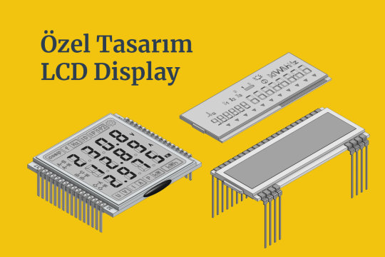
Custom Design LCD Display #lcd #customlcd #display #lcddisplay #lcdmodule #speciallcd #glasslcd #camlcd #backlight #lcdisplay https://www.signal.com.tr/ozel_tasarim_lcd_customized_lcd
#lcddisplay#lcd monitor#lcdmodule#lcdglass#customlcd#display#electronic#engineering#electronicengineering#display technology#screen#lcd#arduino#esp32#esp8266
0 notes
Text
MJPEGs are a great way to play small animations on TFTs 🎞️ 🖥️ 🔄
With our ESP32-S3 TFT experimenter board, we're now able to use the Arduino_GFX https://github.com/moononournation/Arduino_GFX library by moononournation which has native RGB TFT support and excellent example code. This example is playing MJPEG files, a simple animation format https://en.wikipedia.org/wiki/Motion_JPEG with just JPEGs glued together. We wired up a MicroSD card over SPI for quick file storage and retrieval, or 1-bit MMC works, too. files are converted with ffmpeg: 'ffmpeg -i "wash.mp4" -vf "fps=10,vflip,hflip,scale=-1:480:flags=lanczos,crop=480:480" -pix_fmt yuvj420p -q:v 9 wash.mjpeg', natch! And then they play, about 9fps is the rate we're getting for 480x480 pixels.
#adafruit#arduino#electronics#opensource#opensourcehardware#espressif#esp32#espfriends#display#round#raspberrypi#ICN6211#TFT#RGB#tftdisplays#innovation#screendesign#technews#devboard#uniquedesign#screentech#gadgetlove#futuretech#pcbdesign#rgbdriver#esp32s3#ttldisplay#electronicsengineering#prototype#neopixel
13 notes
·
View notes
Note
If I may offer a different take:
Oscar is an engineering major, but ppl keep telling him that STEM majors need to round out their soft skills to move up in the world, so he takes on a business minor bc if he's going to learn about how to work w people he can at least be analytical about it.
He manages to get a business internship at a tech firm, and the entire times he's having to learn about how micro/macro economics has an actual effect on this FAANG company, he just wants to be improving his personal arduino project that displays the top three cars at any given moment on race day (he wants to add voice commands so the display will show him the changing position number of a specific driver if he asks it to).
i was nodding along until you got to the part about the arduino project, and then i cackled because. real
28 notes
·
View notes
Text
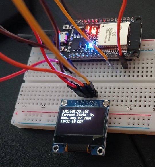
DUINO EDU - DHT11 Sensor & LCD-Display

In diesem neuen Beitrag möchte ich dir gerne zeigen, wie du die Sensorwerte des DHT11 Sensors auf einem LCD-Display per DUINO EDU anzeigen lassen kannst.
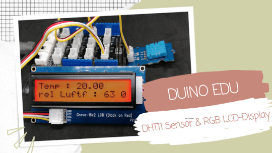
Dieses kleine Projekt ist der Wunsch des lesers Sieglinde L. welche das Projekt gerne mit der grafischen Entwicklungsumgebung DUINO EDU umsetzen möchte.
Benötigte Ressourcen für dieses Projekt
Wenn du das kleine Projekt nachbauen möchtest, dann benötigst du: - einen Arduino UNO*, - ein USB-Datenkabel*, - ein Grove Connector Shield / Base Shield v2 für den Arduino UNO*, - ein DHT11 Sensor mit Grove Schnittstelle*, - ein 20x2 Zeichen LCD-Display (I2C) mit Grove Schnittstelle*, - zwei Grove Kabel* Hinweis von mir: Die mit einem Sternchen (*) markierten Links sind Affiliate-Links. Wenn du über diese Links einkaufst, erhalte ich eine kleine Provision, die dazu beiträgt, diesen Blog zu unterstützen. Der Preis für dich bleibt dabei unverändert. Vielen Dank für deine Unterstützung!
Aufbau der Schaltung
Die Schaltung ist mit den Grove Anschlüssen sehr einfach und schnell erledigt, denn das LCD-Display wird lediglich in einen I2C und der DHT11 Sensor in ein digitalen Connector gesteckt.

Schaltung - Grove DHT11 Sensor & LCD-Display am Arduino UNO
DUINO EDU einrichten / konfigurieren
Bevor wir mit der Entwicklung des Programmes starten können, müssen wir die IDE herunterladen. Wie du dieses machst habe ich dir bereits im Beitrag Arduino Programmierung mit DUINO EDU erläutert. Bei der Programmierung ist mir jedoch aufgefallen das der eingestellte Pfad für das standardmäßige Speichern von Projekten zu Problemen führt. Dieser Pfad wird auch genutzt um Bibliotheken zu referenzieren.
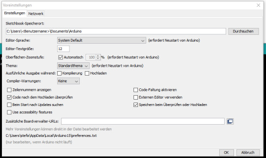
Arduino IDE - Voreinstellungen, Speicherort (default)
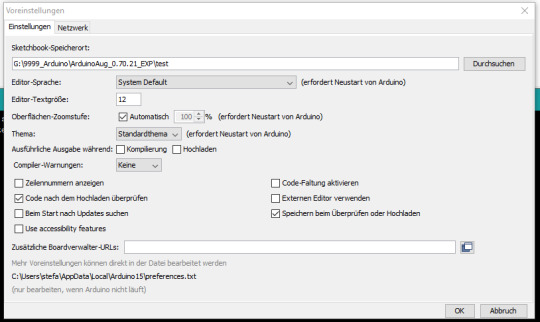
Arduino IDE - Voreinstellungen, Speicherort (custom) Meine Lösung dazu war, den Pfad auf einen anderen Ordner innerhalb der IDE DUINO EDU zu legen.
Programmieren in DUINO EDU
Wenn die Entwicklungsumgebung DUINO EDU fertig eingerichtet ist, dann können wir mit der Programmierung beginnen. Eigentlich ist es keine Programmierung im eigentlichen Sinne denn wir klicken eher per Drag'n Drop GUI Elemente zusammen und daraus wird dann der Code generiert welchen wir auf den Mikrocontroller spielen.

DHT11 Sensordaten am LCD-Display Nachfolgend das YouTube-Video wo ich dir im Detail erläutere wie das Programm aufgebaut wird. https://youtu.be/dJgfNeRQRo8 Fehlende Punkte in der zweiten Zeile In der zweiten Zeile vom LCD-Display werden keine Punkte angezeigt.


Das liegt in diesem Fall an der verwendeten Bibliothek. Wenn man die originale Bibliothek von Seeedstudio in der Arduino IDE verwendet, dann werden alle Zeichen auf dem Display korrekt angezeigt.

Beispiel auf dem RGB LCD-Display mit korrekten Sonderzeichen Das Programm im Detail In der nachfolgenden Grafik zeige ich dir das kleine Programm mit Kommentaren. Du benötigst für das Anzeigen der Sensorwerte auf dem LCD-Display recht wenig GUI Elemente, jedoch werden diese Elemente sehr tief ineinander verschachtelt.
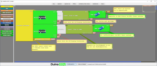
Natürlich kannst du auch den Code etwas lesbarer gestalten und die Werte in Variablen auslagern, jedoch macht dieses den Code nicht viel besser. Den Code kannst du dir auch über nachfolgenden Link als ZIP-Datei herunterladen. Grove DHT11 Sensor & LCD-DisplayHerunterladen
Excurs zum Arduino Code
Schauen wir uns einmal den generierten Code an welcher kompiliert und auf den Mikrocontroller überspielt wird. Zunächst werden die benötigten Bibliotheken importiert. #include #include #include Danach wird geprüft ob das Feld EDU_LCD_ADRESS vorhanden ist, wenn dieses so ist wird eine Bibliothek für das Display importiert, andernfalls wird eine Bibliothek für ein RGB LCD-Display importiert. #if defined (EDU_LCD_ADRESS) #include Duinoedu_LiquidCrystalUp monRgb(EDU_LCD_ADRESS, EDU_LCD_COLS, EDU_LCD_ROWS); #else rgb_lcd monRgb; #endif Im nächsten Schritt wird eine Instanz des DHT Sensor objektes initialisiert mit der zusätzlichen Information das am digitalen Pin D2 ein Sensor angeschlossen ist. DHT monDHT_pin2(2); In der Funktion setup wird das Display und die Kommunikation mit dem Sensor gestartet. void setup(){ monRgb.branch(); monDHT_pin2.brancher(); } Die Funktion loop wird fortlaufend ausgeführt und liest und schreibt die Sensordaten auf das Display. Die Funktionen dabei sind in französischer Sprache (warum auch immer). void loop(){ monRgb.placerCurseurEn(0,0); monRgb.ecrire("Temp.:" ); monRgb.ecrire(String(monDHT_pin2.lireTemperature(),2) ); monRgb.placerCurseurEn(1,0); monRgb.ecrire("rel.Luftf.:" ); monRgb.ecrire(String(monDHT_pin2.lireHumidite(),2) ); delay( 2000 ); } Hier nun der komplette Code: #include #include #include #if defined (EDU_LCD_ADRESS) #include Duinoedu_LiquidCrystalUp monRgb(EDU_LCD_ADRESS, EDU_LCD_COLS, EDU_LCD_ROWS); #else rgb_lcd monRgb; #endif DHT monDHT_pin2(2); void setup() { monRgb.branch(); monDHT_pin2.brancher(); } void loop() { monRgb.placerCurseurEn(0,0); monRgb.ecrire("Temp.:" ); monRgb.ecrire(String(monDHT_pin2.lireTemperature(),2) ); monRgb.placerCurseurEn(1,0); monRgb.ecrire("rel.Luftf.:" ); monRgb.ecrire(String(monDHT_pin2.lireHumidite(),2) ); delay( 2000 ); } Read the full article
0 notes
Text


Monty Jaggers McGraw:
I am writing new BASIC programs to demo at my VCF Southwest 2025 exhibit of my 1979 Tektronix 4054A color vector graphics computer.
One of the programs I am writing is a 1978-1979 Battlestar Galactica TV demo. That TV show had $500,000 of Tektronix vector graphics computers and test equipment and many screenshots of their green vector storage CRT displays - some stills - some animated. These computer graphics were generated on both 1975 4051 and 1976 4081 vector graphics computers - predecessors to my 4052 and 4054A computers (see first photo attached).
Miami Herald TV 1978 magazine interview with the Battlestar Galactica set designer indicated extras on the set stationed in front of the 4051 computers were playing games during filming to increase realism and were so absorbed they kept playing after the cut! (article page attached).
The 4051 and second generation 4052 were the same physical size and used the same CRT and same Display board, but the 4052 and 4054 computers replaced the 800KHz Motorola 6800 CPU with a custom four AMD2901 bit-slice CPU to create a 16-bit address and data bus ALU which emulated the 6800 opcodes and added hardware floating point opcodes to speed up these computers 10x over the Motorola 6800, doubled the BASIC ROM space to 64KB and doubled the RAM space to 64KB!
I created these vector bitmap graphics using a "3D CAD" picture I found on the web of the Battlestar Galactica (last attachment).
As far as I know - there was never any 4050 BASIC program to view bitmap pictures on any of the 4050 computers. The 1979 4014 vector graphics terminal had a grayscale bitmap mode in the Extended Graphics option board, but I have only found a couple of bitmap 4014 images on a single Tektronix demo tape cartridge.
My 4050 BASIC program to display bitmaps works on all 4050 series computers - with an optional Tektronix 4050R12 Fast Graphics/Graphics Enhancement ROM Pack. This ROM Pack speeds up displaying vector images (including vector dot images) 10x over using BASIC MOVE and DRAW commands.
The Battlestar Galactica bitmap image in R12 binary format is 332234 bytes - slightly larger than would fit on a DC300 quarter-inch tape cartridge in the internal tape drive of all three 4050 computers, but would have fit on a 3M DC600 tape cartridge with a capacity of 600KB - it would have been very slow to load.
I designed an Arduino board to emulate the Tektronix 4924 GPIB tape drive - with the help of my software developer. My GPIB Flash Drive board contains a MicroSD card with gigabytes of storage and the Flash Drive emulates a GPIB tape changer, storing all the files of a "tape" in a single directory. I have also attached to this post a photo of my GPIB Flash Drive.
I have recovered almost 100 Tektronix 4050 Tapes and posted the ones I think are the most interesting at this time on my github repository for Tektronix 4051/4052/4054 computers: https://github.com/mmcgraw74/Tektronix-4051-4052-4054-Program-Files I included Tektronix published MATH volumes 1, 2, and 3 and Electrical Engineering, but I don't think they have a lot of use today. I have in my collection but not recovered tapes on Project Management, Statistics, and over 100 more tapes from the very active user group, which Tektronix made collections and published abstracts in their newsletter and the newletter customer got the tape for free. Commercial software like CAD programs were likely encrypted to eliminate copying - since Tektronix 4050 BASIC included a SECRET command which would then encrypt the program file as it was recorded to tape and add a SECRET flag in the tape header that would signal to BASIC ROM when that file was accessed to decrypt the program when it was loaded into memory. One big limiter to the size of the program was RAM in the 4051 was limited to 32KB and the 4052 and 4054 were limited to 64KB of RAM, although Tek BASIC did include commands to allow program "chunks" to be overlayed as necessary. Tektronix used those commands in their 4050 System Tape which was shipped with every system and included a tutorial on many of their BASIC commands. The tutorial ran on the original 4051 with 8KB of memory, and if the program detected 16KB of memory it would APPEND larger program files to speed up the tutorial.

15 notes
·
View notes
Text
SERVO DISTANCE INDICATOR USING ARDUINO UNO
INTRODUCTION
Distance measurement is a fundamental concept in various fields, including robotics, automation, and security systems. One common and efficient way to by emitting sound waves and calculating the time it takes for the waves to reflect back from an object, allowing accurate measurement of distance without physical contact.
In this project, we will use an HC-SR04 Ultrasonic Sensor in conjunction with an Arduino microcontroller to measure the distance between the sensor and an object. The sensor emits ultrasonic waves and measures the time it takes for the waves to return after reflecting off the object. By using the speed of sound and the time measured, the distance is calculated. This simple yet powerful setup can be applied in a variety of real-world applications such as obstacle detection in robots, parking assistance systems, and automatic door operations.

WORKING PRINCIPLE
1. Servo Movement: The servo motor rotates to different angles (0° to 180°). The ultrasonic sensor is mounted on top of the servo and moves with it.
2. Distance Measurement: At each position, the ultrasonic sensor sends out an ultrasonic pulse and waits for the echo to return after hitting an object. The Arduino records the time taken for the echo to return.
3. Distance Calculation: The Arduino calculates the distance to the object based on the time recorded and the speed of sound (0.0343 cm/µs).
4. Servo as Indicator: The servo motor's position provides a physical indication of the direction of the detected object. As the servo moves across a range of Image map out objects in different directions based on distance.
5. Visual Output: The Arduino can also send the distance and angle data to the serial monitor, creating a real-time visual representation of the detected object positions.
APPLICATIONS
1. Autonomous Robots and Vehicles
2. Radar Systems
3. Parking Assistance
4. Security Systems
5. Environmental Scanning in Drones
6. Warehouse Management and Automation
7. Industrial Automation
8. Robotic Arm Guidance
9. Collision Avoidance in UAVs/Robots
10.Interactive Displays or Art Installations
11.Smart Doors and Gates
CONCLUSION
The Servo Distance Indicator Project successfully demonstrates the integration of an ultrasonic sensor and a servo motor to create an effective distance measurement an object, the project provides real-time feedback through the movement of a servo motor, which indicates the measured distance via a visual representation.
7 notes
·
View notes