#beziercurves
Explore tagged Tumblr posts
Visit Tumblr Blog
Explore Tumblr blogs with no restrictions, modern design and the best experience.
Last Seen Tumblr Blogs


Fun Fact
1,644 Tumblr posts in 1 second.
Text

🌷COMMISSION Skeb納品 リクエストありがとうございました〜🍒 https://skeb.jp/@Kbyskeb/works/6
#skeb#illustration#commission#fanart#vector#vectorart#deformed#chibi#adobeillustrator#Bezier#beziercurve
2 notes
·
View notes
Text

VECTOR TRACING Transform your raster images into stunning vectors with our expert tracing services. Vector Artwork Services at. https://vitessegraphic.com/ Email: [email protected]
#vectorization#rastertovector#convertimagetovector#imagetracing#vectorgraphics#adobeillustrator#inkscape#vectorizelogo#svg#vectorizeimage#vectorfile#pathtotracing#pentool#beziercurves#vectorartwork#RasterToVector#VectorGraphics#VectorDesign#AutoVectorization#VectorIllustration#VectorizeMe#DigitalArt#vectorizeit#vectortracing#vectordesign#vectorart#vectorconversion#raster2vector#vectormagic#vectorizing
0 notes
Text
Day 21 of Genuary 2022 Challenge: "Combine 2 (or more) of your pieces from previous days to make a new piece - Day 8 (Single curve only) + Day 17 (Three colours)
0 notes
Photo

Fill #illustrator #pentool #beziercurves https://www.instagram.com/p/CSckfiSIaAc/?utm_medium=tumblr
0 notes
Photo

My first official illuminated letter. #matsbootcamp2017 #makeartthatsells #lettering #illustration #beziercurves #m #graphicdesign (at Pixelzz Design)
1 note
·
View note
Photo

Drawing #Beziercurves - source Bezier Curves and #Picasso
17 notes
·
View notes
Photo

Always had trouble coloring in between the lines, so why not make them instead? ✍️ Here’s a preview of a new design in the works. Any guesses? - - - #lineartwork #digitaldesigns #beziercurves #techie #techy #artandtechnology #artandtech #graphicdesigns #screendesign #uxui #graphicdesigning #softwareengineer #softwaredev #siliconvalleylife #geeklife #geekstuff #gadgetgeek #mazerunner #artisanmade #artisanmadegoods #geekgifts #solopreneurlife #entrepreneurjourney #entrepreneurmind #creativetechnology #technologist #computerscientist #multimediadesign #uniqueart #conceptualillustration https://instagr.am/p/CMVFj7sBDu8/
1 note
·
View note
Video
instagram
Ease in / ease out with the Motion Editor in Animate CC. The right shape of the curve is the key to the softness of the animation. If the bezier curve it cool you can copy it and paste it to ease the rotation of the wheels. After that the work is half done. And even more important: Handle your ammunition with care otherwise people get harmed. #animation #animatecc #motiondesign #motiongraphics #beziercurves #easeout #easein #illustration https://www.instagram.com/p/CBVu5TfnOcX/?igshid=u067civtzw9l
0 notes
Photo

2D Scene editor
Using OpenGL and GLSL to create an simple 2D scene editor which can add triangle and bezier curves by clicking the point, and change color, translate, scale, and rotate.
0 notes
Photo
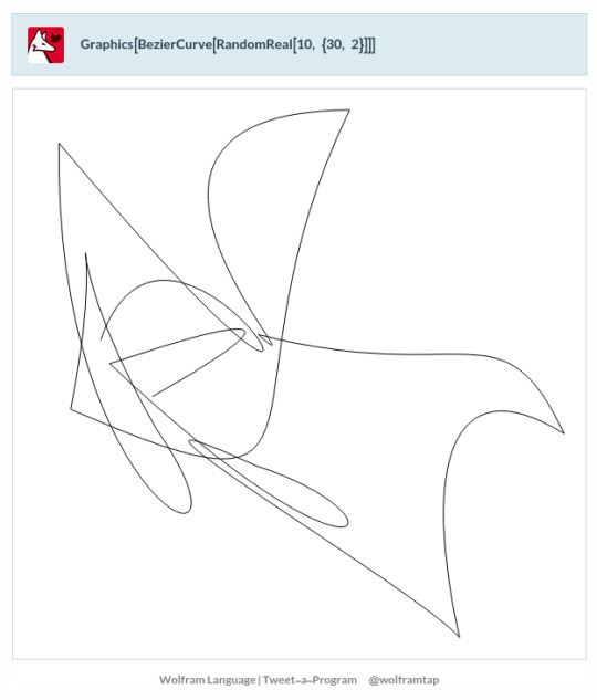
Graphics[BezierCurve[RandomReal[10, {30, 2}]]]
https://twitter.com/wolframtap/status/1625567194150014979
0 notes
Photo

I ACCEPT YOUR CHALLANGE!! ( I shout... a few mouths to late...😅)
So, you know when the hype was up for yellow- and blue zircon?? Well, there was this one guy who was like “Okay guys, I dare you to draw blue and yellow like this.” and I was like “You know what, I’ll bite” and I actually finished the sketch the same day as I saw the post buuuut- who said I would post it...
But I actually really liked this one and now I’ve also refined it and made an outline! But not just any outline, NOPE!
I’ve drawn this... with just my tablet pen. That may not sound too incredible, but I have never been good with doing outline with the pen. So I’ve always used the “beziercurve tool”, but yesterday (or so) I tried drawing with only the pen and it turned out a lot better then I thought it would!!
So now I'm in a groove~
But anyway, hope you like it!
#steven universe#steven universe blue zircon#steven universe yellow zircon#so many birthdays#steven universe pearl#steven universe amethyst#the sketch is a little better but it felt like it was a little too hard to see yellow so I desided to outline it#it's nothing fancy#but it's something :)
5 notes
·
View notes
Photo

Stroke #illustrator #pentool #bezierCurves https://www.instagram.com/p/CSckatnILAU/?utm_medium=tumblr
0 notes
Photo

Blender - Glas Modeling - Methode: Bezier
- ich habe mir eine Vorlage angelegt, um Arbeitsschritte zu reduzieren
- der View-Port ist auf Right Ortho eingestellt
- als Referenz kann man ein Foto in den Hintergrund laden
- einen Bezier-Curve-Spline hatte ich bereits erstellt; hier lösche ich z.B. alle Punkte bis auf den Bodenbereich; natürlich kann man auch mit Shift + A / Curve / Bezier eine neue Kurve/Pfad/Spline erzeugen (Anm.: Blender zeigt leider eine wenig intuitive Usability mit den Kurvenpunkten; man erhält zu Beginn 2 Vertices, die eine kleine Kurve darstellen; diese dienen als Ausgangspunkt für den Spline)
- ich nutze den letzten Punkt meiner Kurve aus dem Glasfuss, mit strg + Linksklicken kann ich neue Punkte hinzufügen (Orientierung an der rechten Hälfte der Fotovorlage
- es muessen für die Glasdicke Punkte auch “nach innen” positioniert werden
- Feinkorrekturen der Punkte, ggf. mit Taste V den Modus ändern (Harte/weiche Interpolation)
- in den Objektmodus wechseln, Bezier-Kurve ist ausgewählt (orange)
- nun mit Add/Curve/Circle einen Kreis hinzufügen; rechts im kleinen “Werkzeugmenü” bei der Option Spilnes nun auf “Bevel Objekt” klicken, um die BezierCurve zuzuweisen
- dann wird ein 360° Rotationskörper erzeugt; ggf. rechts neben der Bezierkurve im Arbeitsfenster positionieren und ausrichten (ggf. skalieren)
- ggf. im Edit-Modus die Bezierpunkte optimieren; jede Änderung wird dann direkt im Rotationskörper angezeigt

- den Rotationskörper auswählen und mit Altl + C in ein Mesh konvertieren; in der isometrischen Ansicht könnte man die beiden Löcher am Boden und im Glas schließen (den jeweiligen Ringbereich mit Alt + Rechtsklick auswählen, E und Enter, dann S und 0 tippen oder bei der Skalierung manuell ziehen und schliessen
- im Objekt-Modus ist das Glas ausgewählt, dann Exportieren (Selectes only + Häkchen bei Triangulation aus; Formate z.B. *.dae oder *.fbx)
ALTERNATIVE METHODE - mit Spin arbeiten ...
Hier zeigen sich aber diese Probleme

0 notes
Photo

Beziercurve icon http://www.clipartx.com/icon-Clipart/beziercurve--106487
0 notes
Text
youtube
This video lecture describes about the Bezier Curves & Problems related to Bezier Curves #CAD/CAM [By: Er. C.S.Nagendra]
#ComputerAidedDesignAndManufacturing
#BezierCurves
#ProblemsOfBezierCurves
#Tutorials
0 notes
Text
Week 11

I wanted to explore more to show diversity. I wanted to do this by trying curves in op art to try show it in a different way. I was inspire by Bridget Reilly’s work.

https://processing.org/reference/bezier_.html
https://processing.org/tutorials/curves/
Wanting to explore more about the depth I can get to I tried using curves. The specific name for these are known as ‘bezier curves’. They are defined through anchor and control points.
Small scale:
I find it easier to learn as I start to play around and start understanding new functions, below are some examples that I have created so far that.


I drew the bezier curve shape multiples of times to show overlapping. When discussing with my teachers on how to fit this to the whole page, they gave me the idea of scaling it (making the size of the screen large). They told me to do this so the detail is really seen and it the effect is seen visually more. This way it would fit too.
Large Scale:

When sizing to bigger scale. I thought that changing the coordinates of the points int he vertexes would help me get the same design but in a bigger size. However it was more than this to get it to work.
Understanding bezier:

Tried to open outcome in a tiff file however its too large and since it saves as a bitmap it is really blurred as its more zoomed in. To fix this the save format had to change to a pdf instead.
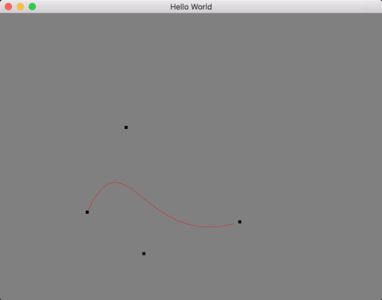
vertex(30, 70); // first point bezierVertex(25, 25, 100, 50, 50, 100);
I have gotten help with understanding this. On the website it shows these as anchor point and the handles similar to pen tool patterns from illustrator. This is how the curve is shaped. The first vertex is the starting point so x and y positions of where the curve starts. The next two numbers and and last two numbers in the bezier identify how far it will go in and where to stop. The middle two numbers create the maximum point of the curve, with this information I am willing to try and make something unique and cool at the same time.
vertex(0, i); // first point bezierVertex(100, i+100, 4800, i+100, 5000, i);
I have tried to create this type of pattern seen above by increasing the x value from the vertex to the bezier to a very high number. I also changed the distance from max x which is 5000 to 4800 so it creates the ‘u’ shape. I did i+100 which is the so everytime it hits the y of the first point and the y of the second point 100 is added to ‘i’ it will start off with 100 since i is 0 and go on.

By increasing the i=i+... it changes the space between the lines which does not give the pattern effect that I am trying to get.

I tried to make the second point of the first coordinate in the bezierVertex add by 1000 to see what effect it gives out. In this I learnt that the curve goes down and up again.
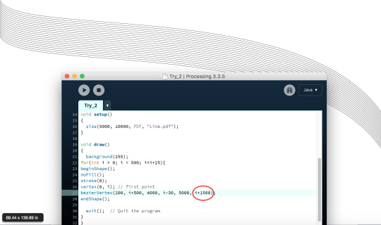
I changed the first y coordinate to i+500 instead of 100 so it is increased by 500 and have also changed the last points y coordinate to i+1500. This made the curve be drawn out more.

By making the bezierVertex first y value i+2000 and the last y value i+4000, there is a first shallow curve and a second deep curve, making it more detailed.

I tried on expanding the conditional statement for the for loop. I had increased it to 500. I had also changed i = i+3 to see what effect I would get. I quite liked it as it was bunched up more however you can still see the pattern the lines create. I also changed the y of my vertex point to i*2 and had decreased the values of i* in the bezierVertex to see its effects and I quite liked it.
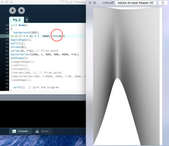
I had changed the limitation to i<5000 so it fitted the screen along with making i=i+20 now so it is accordingly to the limitation and has that little bit of pattern you can see

Tried putting two curves together. I have increased the vertex’s x value by one is 0 other is 1000. The x value for the first point of the bezier goes from 1000 to 2300. And the x value at the end point goes from 1500 to 4000. Which is why there are three types of columns in the image above as it is trying to connect them both but finishes at 1500 and other finishes at 4000.

I tried to use more bezierCurves by overlapping them to see what type of curve I get. I did this by keeping everything in the bezierVertex the same however I changed the x coordinate of the vertex in every single one.

Once again I have created a pattern which is overlapping. But this time all the x values in the shapes change. Which is why there is a oval gap thing at the end of each shape.
Multiples for loops

I tried using the same type of outcome from above by changing all the values of x however this time for every shape I drew I would have a for loop. This what helped with the pipe effect. So for this I would have to change the x value based on the limitation given in the for loop.

I had developed the idea from before that everyone liked after understand bezierCurves. I created this by changing the first point’s x value and bezierVertex’s x value I had to keep everything else the same otherwise it would look weird. I realised that I made this in colour as I just editied from the previous one and also after enlarging it I don’t really think it shows the movement effect anymore.
Note: I realised I have not included all the code in some, most of its repeated and changes in the same range in that value everytime it is drawn. I didn’t get to share this code as the page was massive and I didn’t wanted to show repetition of this.
Colours on favourites:
Liking what I have done so far this time along I wanted to play around with contrasting colours to see which one gives out the best effect. I chose two ideas which then I have used below with colours on it. I only used two colours as I wanted the colour to show contrast and not be so heavy on the composition itself.


Pipe


0 notes