#integrated esp arduino
Explore tagged Tumblr posts
Visit Tumblr Blog
Explore Tumblr blogs with no restrictions, modern design and the best experience.
Last Seen Tumblr Blogs


Fun Fact
Tumblr is available in 18 languages.
Text
Importance of Mechatronics Engineering
Mechatronics and IoT Engineering are among the most crucial and rapidly evolving disciplines in modern technology.
Interdisciplinary Innovation: Mechatronics blends mechanical, electrical, computer, and control engineering, enabling the creation of smart, efficient systems. Automation & Robotics: Vital in the design and control of robots, CNC machines, and automated manufacturing systems, helping industries scale up productivity.

Enables development of intelligent systems like drones, autonomous vehicles, and smart appliances. Improves design and manufacturing processes, reducing errors and increasing system reliability.
Real-World Applications: Automotive, Medical devices, Aerospace.
Connectivity & Data-Driven Decisions: IoT connects devices to collect, share, and analyze data, enhancing decision-making in real time.
Smart Infrastructure: Enables smart homes, smart cities, and industrial automation.
youtube
#basic electronics#digital painting#digital circuit#arduino#integrated circuits#integrated esp arduino#iotsolutions#iot platform#iot applications#iotmanagement#iot circuits#iot projects#security systems#artificial intelligence#Youtube
0 notes
Text

ESP32 WROVER Kit, Compatible with Arduino IDE The starter kit is based on the development board from esp32 wrover. It integrates with bluetooth and wireless.A powerful dev board for IOT module project development.ESP32-WROVER series is developed by Espressif Systems, below is key features and applications are summarized: I. ESP32 Wrover Specifications - Chip Architecture - Dual-core SoC (ESP32-D0WD or D0WD-V3) with a clock speed of 80–240 MHz (dynamic frequency scaling)13 - 520 KB integrated SRAM, expandable via external SPI RAM/Flash1 - Built-in 4–16 MB SPI Flash and 8 MB SPI PSRAM (depending on model, e.g., WROVER-B/E)37 - Wireless Connectivity - 2.4 GHz Wi-Fi (802.11 b/g/n) with up to 150 Mbps throughput36 - Dual-mode Bluetooth: Classic (BT) and Low Energy (BLE)36 - Peripherals & Interfaces - SPI, I2C, UART, SDIO, Ethernet interfaces3 - Support for capacitive touch, Hall effect sensors, PWM outputs37 II. ESP32 Wrover Kit Development Environment & Tools - Programming Frameworks - Official ESP-IDF framework (FreeRTOS + LwIP stack), C/C++-based16 - Arduino IDE compatibility via ESP32 board manager28 - Optional Python/C hybrid development using Zerynth Studio5 - Hardware Debugging Tips - Use 5V power for camera modules (3.3V may cause image instability)2 - Adjust SPI pin definitions (e.g., SCK=14, MISO=12) based on hardware layout4 III. ESP32 Devkit Typical Applications - IoT Devices - Sensor networks, smart home controllers with ultra-low-power modes (sleep current Read the full article
0 notes
Text

Introducing the latest version of the NodeMcu ESP8266 CH340 Module – a cutting-edge, budget-friendly WiFi technology. This advanced board utilizes modern, high-level LUA based technology and offers an all-in-one design, making it incredibly easy to integrate into your current Arduino projects or any development board with available I/O pins.
Utilizing modern Internet development tools, like Node.js, can effectively accelerate the implementation of your ideas with the assistance of the built-in API provided by NodeMCU. Based on ESP8266 technology, NodeMCU harnesses a wealth of online resources to further enhance its capabilities.
The NodeMCU ESP8266 CH340 Module is equipped with ESP-12 based serial WiFi integration, allowing for easy access to GPIO, PWM, ADC, I2C, and 1-WIRE resources. It also features a built-in USB-TTL serial using the dependable CH340 for superior stability on all compatible platforms. Additionally, this wifi-module is one of the most cost-effective options currently available in the market. Its latest version is known as V3 or Version3. In this tutorial, we will provide instructions to connect any version of ESP8266 NodeMcu (V1, V2, or V3).
Hardware IO similar to Arduino – An advanced API for easily configuring and manipulating hardware, reducing repetitive tasks. Write code in Lua script, just like with Arduino but in a more interactive manner.
The Event-driven API for network applications in Nodejs style enables developers to easily write code for a compact 5mm5mm sized MCU. This greatly accelerates the development process for IOT applications.
The ESP8266 Development Kit combines GPIO, PWM, IIC, 1-Wire, and ADC on a single board. By using the NodeMCU Firmware, it allows for quick and efficient development.
The NodeMcu is a useful tool for creating IoT prototypes. It is an open-source firmware and development kit that allows you to write Lua scripts with ease. This Development Kit is built on the ESP8266 platform and includes integrated features such as GPIO, PWM, IIC, 1-Wire, and ADC, all conveniently housed on one board.
Attributes of NodeMcu ESP8266 CH340 Module are:
Utilizes CH340G in place of CP2102.
The standard for wireless technology, specifically 802.11 b/g/n, eliminates the need for cables.
The WiFi operates at 2.4GHz and offers WPA/WPA2 security mode.
Provide assistance for the three available operating modes: STA, AP, and STA AP.
The TCP/IP protocol stack is integrated to facilitate the handling of multiple connections from TCP Clients (up to a maximum of 5).
The data communication interface supports UART and GPIO.
OTA, or remote firmware upgrade, is a quick and efficient way to update your device’s firmware without having to physically connect it to another device.
Assist the enhancement of Smart Link Smart Networking.
The IO Pin is an integral part of ESP8266.
There is no need to download the reset function.
An excellent toolkit for enhancing ESP8266 capabilities.
The WI-FI with the most affordable price.
For hardware IO compatible with Arduino.
Maximize efficiency in developing your IOT applications.
This product boasts a range of impressive features, including its open-source capability, interactivity, programmability, affordability, user-friendly design, intelligent functions, and WI-FI connectivity.
The integrated WI-FI MCU ESP8266 development kit offers effortless prototyping capabilities.
Our platform offers the most cost-effective solution for developing IoT applications.
NodeMCU ESP8266 CH340 Module features a built-in USB-TTL serial port, equipped with the highly dependable industrial-grade CH340G chip, ensuring unrivaled stability across all compatible platforms.
The Advanced API offers hardware IO capabilities that greatly minimize the need for repetitive tasks involved in setting up and managing hardware.
The network application’s event-driven API enables developers to write Nodejs-style code for a compact 5mm*5mm MCU.
0 notes
Photo

* 🇧🇷 Projeto Zeus Multiplataforma Compatível com Arduino, PIC , ESP01, 07, 12 e 32, STM. RTC integrado, 5 Reles e Leds piloto. ------------------------- youtube.com/ProjetosEletronicos ------------------------- 🇺🇸 Zeus Multi Platform Project Compatible with Arduino, PIC , ESP01, 07, 12 and 32, STM. INTEGRATED RTC, 5 Reles and Pilot Leds ------------------------- #zeus #multiplataforma #arduino #pic #stm32 #STM32F103C86 #esp #esp8266 #esp01 #esp32 #esp12 #protótipo #desenvolvimento #educacional #treinamento #walproj #projetosmaker #projetoseletronicos #hardware (em Projetos Eletronicos) https://www.instagram.com/p/CPMGKUYrp4D/?utm_medium=tumblr
#zeus#multiplataforma#arduino#pic#stm32#stm32f103c86#esp#esp8266#esp01#esp32#esp12#protótipo#desenvolvimento#educacional#treinamento#walproj#projetosmaker#projetoseletronicos#hardware
2 notes
·
View notes
Text
14 Awesome Arduino Cloud Features You Never Knew Existed
Tweet
There are dozens, if not hundreds of amazing Arduino Cloud features. So it’s perfectly understandable if you’ve missed some of them.
So we’ve put together a list of our favorite Arduino Cloud features that you might not know existed.
1) Auto-generate Sketches
We’ve talked elsewhere about getting an understanding of what cloud computing really is, and how it’s not just the domain of experts. The cloud is how total beginners can get started much more easily. There’s no better demonstration of that than our first top Arduino Cloud feature; auto-generated sketches.
When you create a new “Thing” in your Arduino Cloud, you add various bits of info to it. Wi-Fi connection credentials, and any variables you want to control or monitor. The Cloud automatically generates a starting sketch from this info. That sketch can then be sent to your boards, so all your initial configuration is taken care of, without a single line of code.
2) Device-to-Device Communication
There’s simply no easier way to make two microcontroller boards talk to each other than Arduino Cloud. We’ve covered in detail how easy it is to wirelessly connect your boards.
This isn’t just for Arduino devices either. If you want any combination of Arduino, ESP32 and ESP8266 devices to work together, this is how you do it.
3) Over-the-Air Updates
Working through your Arduino Cloud means you don’t have to disconnect any Arduino boards when updating them. If you want to edit or add a new sketch, it can all be done wirelessly, over-the-air.
Anyone who’s had to dismantle a project or device to get to a board’s USB socket will appreciate the simple, vital value of this feature. It’s one of those things that you’ll wonder how you ever lived without.
4) Support for ESP Boards
There’s a reason we call it the Arduino IoT Cloud. This is an all-encompassing platform for Internet of things, home automation, and electronics project control and management. So first we added support for ESP8266 devices. More recently, experimental support for ESP32 boards became available.
So even if your project doesn’t actually have any Arduino products in there, the Cloud is just as useful. Secure, private, and accessible to all kinds of IoT and maker devices.
5) Trigger Actions on Cloud Events
Arduino Cloud makes it super easy to do things that you might normally need the IDE for. But it’s also got lots of exclusive features that you only get in the Cloud.
For example, there are actions that can be triggered based on your board’s interactions with your Arduino Cloud. You can include actions within your sketches when a Cloud connection is successful, and when the Cloud has synced with a device. Or perhaps most useful of all, trigger an action if Cloud connectivity is lost. Getting an indication that a project has disconnected could be incredibly useful!
Here’s an example of using these actions within a sketch.
6) Sharing Your Dashboards
Dashboards are control panels within your Arduino Cloud. It’s one of the most powerful Arduino Cloud features, and essential to making full use of Cloud control. But what’s often overlooked is that you can share dashboards with anyone you want.
For example, let’s say you’re using Arduino Cloud to control your home automation. You can set up a dashboard for a tablet in the living room that the whole family can use, but doesn’t have sensitive admin controls in there. And then another for people to use on their phones.
All Cloud plans include unlimited dashboards. And anyone can have a free Cloud account. So you can create as many dashboards as you like, and share them with literally anyone, anywhere.

7) Alexa Integration
Natural language voice control is genuine Star Trek stuff. So it’s no wonder people love the functionality of Alexa. Did you know it’s incredibly easy to connect your Arduino Cloud to Alexa? And once you have, it effectively adds voice control to every board, and every project. Nothing else needed.
There’s literally no easier way to make an Alexa-controlled device or project than with your Arduino Cloud. You’ll never look back, and you’ll always have someone to talk to.
youtube
8) Full API Integration
For the engineers, coders, developers and those among you who’ve been using Arduino for a long time, API integration is the powerhouse secret feature you’ve been looking for.
The API can be called with any HTTP client, or with languages like Javascript, Python, Golang and more. It’s what you need to incorporate the power of Arduino Cloud features into your systems, platforms and projects.
9) Use IFTT, Zapier and More with Webhooks
There are lots of reasons you might want to include control platforms outside of your Arduino Cloud. Like sending an email or a Tweet when you press a button on a Nano, or a device disconnects from the Cloud (see above).
That’s what webhooks are for, and they give you a universal way to send commands out of Arduino Cloud, and into… well, anything!
IFTTT and Zapier are great examples of services that can do almost anything from a webhook. Get to know this feature, and connected projects suddenly have easy access to the whole web.

10) Easy Firmware Updates
When you connect a new Arduino board, your Arduino Cloud automatically checks its firmware version. If there’s an update available, it offers you the option of applying that update.
Very easy, and you don’t have to worry about finding the correct/latest firmware version yourself. This simple, background function makes sure your boards and projects always have the latest features, security updates and bug fixes.
For people who use a lot of Arduino devices, it’s worth adding them to the Cloud for this feature alone.
11) Full Dashboard Customization
We’ve already talked about unlimited dashboards in your Arduino Cloud. Creating them is easy, but did you know you can customize them too?
Anyone who’s dipped their toe in the home automation waters knows how essential dashboard editing is. Some platforms work great, but offer very little when it comes to controlling your dashboard layout. For many people, that’s a deal breaker.
Your Arduino Cloud widgets can easily be added, edited, removed, repositioned and resized in any configuration you want. It’s as simple as drawing and resizing boxes, but the result makes your Cloud projects infinitely more useable.

12) Watchdog Timer
The Arduino Cloud automatically runs a watchdog timer that will reset your board, hardware or project if it crashes. This is a small feature, but a powerful one that can keep your projects running while unattended.
It means you never have to manually reset it when you eventually realize it’s not been running all day. You can have devices running remotely (very remotely, with SIM or LoRa connectivity) and be sure they’re robust enough to keep on ticking.
It’s included and running automatically, but can easily be disabled if you don’t need it.
youtube
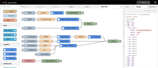
13) Node-RED Integration
Arduino provides a super easy way to use Node-RED for IoT automations. This is a powerful, but very easy-to-use visual programming platform specifically designed for IoT projects.
Complex automations using advanced triggers like sunrise or sunset, presence detection, combined actions or sensor readings and so much more. The possibilities are endless, and learning Node-Red is incredibly easy. Get to grips with this feature, and you’ll be creating IoT automations that would otherwise need an experienced coder.
13A) Fully Functional Free Account
One of the best kept secrets of the Arduino Cloud is that if you’re registered on the Arduino website or forum, you already have a free Cloud waiting for you. Simply head on over to the Cloud site and get started with unlimited dashboards and unlimited sketches. The free tier of Arduino Cloud is fully functional, and it’s ready and waiting for you to give it a try.
In fact, it’s the perfect option especially if you haven’t used Arduino before! Give it a shot and let us know what you think. No credit card required; just your creativity and a passion for connected projects.
TRY YOUR FREE ARDUINO CLOUD RIGHT NOW
The post 14 Awesome Arduino Cloud Features You Never Knew Existed appeared first on Arduino Blog.
Bookmark It


Hide Sites
$$('div.d43157').each( function(e) { e.visualEffect('slide_up',{duration:0.5}) });
14 Awesome Arduino Cloud Features You Never Knew Existed was originally published on PlanetArduino
1 note
·
View note
Text
Ubidots + ESP32- Predictive Machine Monitoring
Predictive analysis of machine vibration and temp by creating mail events and a record of vibration in google sheet using Ubidots.

Story
Predictive Maintenance and Machine Health Monitoring
The rising of new technology i.e, the Internet of Things, heavy industry has started adopting sensor-based data collection to solve its biggest challenges, principal among them process downtime in the form of shutdowns and process delays. Machine monitoring also called predictive maintenance or condition monitoring is the practice of monitoring electrical equipment through sensors in order to accumulate diagnostic data. To achieve this, data acquisition systems and data loggers are used to monitor all kinds of equipment, such as boilers, motors, and engines. Following condition are measured:
Temperature and Humidity Data Monitoring
Current and Voltage Monitoring
Vibration Monitoring: In this article, we will read Temperature, vibration and publish the data in Ubidots. Ubidots supports graphs, UI, notifications, and emails. These features make it ideal for predictive maintenance analysis. We will also get the data in google sheets which will make predictive maintenance analysis more easier.
Hardware:
ESP-32
IoT Long Range Wireless Vibration And Temperature Sensor
Long-Range Wireless Mesh Modem with USB Interface
Software Used:
Arduino IDE
Ubidots
LabView Utility
Library Used:
PubSubClient Library
Wire.h
Arduino Client for MQTT
This library provides a client for doing simple publish/subscribe messaging with a server that supports MQTT
For more information about MQTT, visit mqtt.org.
Download
The latest version of the library can be downloaded from GitHub
Documentation
The library comes with a number of example sketches. See File > Examples > PubSubClient within the Arduino application.Full API Documentation.
Compatible Hardware
The library uses the Arduino Ethernet Client api for interacting with the underlying network hardware. This means it Just Works with a growing number of boards and shields, including:
Arduino Ethernet
Arduino Ethernet Shield
Arduino YUN – use the included YunClient in place of EthernetClient, and be sure to do a Bridge.begin() first
Arduino WiFi Shield - if you want to send packets greater than 90 bytes with this shield, enable the MQTT_MAX_TRANSFER_SIZE () option in PubSubClient.h.
Sparkfun WiFly Shield – when used with this library
Intel Galileo/Edison
ESP8266
ESP32The library cannot currently be used with hardware based on the ENC28J60 chip – such as the Nanode or the Nuelectronics Ethernet Shield. For those, there is an alternative library available.
Wire Library
The Wire library allows you to communicate with I2C devices, often also called "2 wire" or "TWI" (Two Wire Interface), can download from Wire.h
Basic Usage
Wire.begin()Begin using Wire in master mode, where you will initiate and control data transfers. This is the most common use when interfacing with most I2C peripheral chips.
Wire.begin(address)Begin using Wire in slave mode, where you will respond at "address" when other I2C masters chips initiate communication.
Transmitting
Wire.beginTransmission(address)Start a new transmission to a device at "address". Master mode is used.
Wire.write(data)Send data. In master mode, beginTransmission must be called first.
Wire.endTransmission()In master mode, this ends the transmission and causes all buffered data to be sent.
Receiving
Wire.requestFrom(address, count)Read "count" bytes from a device at "address". Master mode is used.
Wire.available()Returns the number of bytes available by calling receive.
Wire.read()Receive 1 byte.
Steps to send data to Labview vibration and temperature platform using IoT long-range wireless vibration, temperature sensor and long-range wireless mesh modem with USB interface:
First, we need a Labview utility application which is ncd.io Wireless Vibration and Temperature Sensor.exe file on which data can be viewed.
This Labview software will work with ncd.io wireless Vibration Temperature sensor only
To use this UI, you will need to install following drivers Install run time engine from here 64bit
32 bit
Install NI Visa Driver
Install LabVIEW Run-Time Engine and NI-Serial Runtime
Getting started guide for this product.
Uploading the code to ESP32 using Arduino IDE:
Download and include the PubSubClient Library and Wire.h Library.
You must assign your unique Ubidots TOKEN, MQTTCLIENTNAME, SSID (WiFi Name) and Password of the available network.
Compile and upload the Ncd__vibration_and_temperature.ino code.
To verify the connectivity of the device and the data sent, open the serial monitor. If no response is seen, try unplugging your ESP32 and then plugging it again. Make sure the baud rate of the Serial monitor is set to the same one specified in your code 115200.
Serial Monitor Output:

Data on serial monitor of Arduino IDE.
Making the Ubidot Work:
Create the account on Ubidot.
Go to my profile and note down the token key which is a unique key for every account and paste it to your ESP32 code before uploading.
Add a new device to your Ubidot dashboard name ESP32.


Now you should see the published data in your Ubidots account, inside the device called "ESP32".
Inside the device create a new variable name sensor in which your temperature reading will be shown.


Now you are able to view the Temperature and other sensors data which was previously viewed in the serial monitor. This happened because the value of different sensor readings is passed as a string and store in a variable and publish to a variable inside device esp32.
Create a dashboard in ubidots.

Go to data select dashboard and inside dashboard create different widgets and add a new widget to your dashboard screen.
OUTPUT
Now as the temperature/vibration increases and decreases new data available inside the various variable.

Creating Events in Ubidots

1) Select Events (from the Data dropdown).

2) To create a new event, click the yellow plus icon in the upper right corner of the screen.
Types of Events: Ubidots support already integrated events to allow you to send Events, Alerts, and Notifications to those who need to know when they need to know. Ubidots' prebuilt integrations include:
Email notifications
SMS notifications
Webhook events - learn more
Telegram notifications
Slack notifications - learn more
Voice Call notifications - learn more
Back to Normal notification - learn more
Geofence notifications - learn more
3) Then choose a device and associating variable that indicates the devices' "values".

4) Now select a threshold value for your event to trigger and compare it to device values and also select time to trigger your event.
5) Establish and configure which actions are to be executed and the message to the receiver: Send SMS, Email, Webhooks, Telegrams, Phone Calls, SLACK, and webhooks to those who need to know.

6) Configure the Event notice.

7) Determine the activity window the events may/may not be executed.

8) Confirm your Events.
The output of Event in Your Mail:

Export Your Ubidots Data to Google Sheets:
In this, we can extract the data stored in the Ubidots cloud for further analysis. The possibilities are enormous; for instance, you could create an automatic report generator and send them to your customers every week.
Another application would be device provisioning; if you have thousands of devices to deploy, and their information is in a Google Sheet, you could create a script to read the sheet and create a Ubidots data source for every line on the file. Steps to do this-
Create a Google Sheet and add two sheets to it with these names:
Variables
Values
From your Google Sheet, click on "Tools" then "Script Editor...", then "Blank Project".
Open the Script Editor.

Add the code below (in the code section) to the script Script.
Done! now open your Google Sheet again and you'll see a new menu to trigger the functions.

Result:

1 note
·
View note
Text
Swordsoft layout serial number

SWORDSOFT LAYOUT SERIAL NUMBER HOW TO
SWORDSOFT LAYOUT SERIAL NUMBER CODE
However, if you have peripherals connected to those pins, you may have trouble trying to upload new code, flashing the ESP32 with new firmware, or resetting the board. More information on the ESP32 Boot Mode Selection can be found here. The board puts the pins in the right state for flashing or boot mode. On most development boards with built-in USB/Serial, you don’t need to worry about the state of these pins. These are used to put the ESP32 into bootloader or flashing mode. The ESP32 chip has the following strapping pins:
SWORDSOFT LAYOUT SERIAL NUMBER HOW TO
Learn how to use interrupts with the ESP32: Learn more about SPI communication protocol with the ESP32 using Arduino IDE: ESP32 SPI Communication: Set Pins, Multiple SPI Bus Interfaces, and Peripherals (Arduino IDE) InterruptsĪll GPIOs can be configured as interrupts. Learn more about I2C communication protocol with the ESP32 using Arduino IDE: ESP32 I2C Communication (Set Pins, Multiple Bus Interfaces and Peripherals) SPIīy default, the pin mapping for SPI is: SPI If you want to use other pins when using the wire library, you just need to call: Wire.begin(SDA, SCL) When using the ESP32 with the Arduino IDE, the default I2C pins are: The ESP32 has two I2C channels and any pin can be set as SDA or SCL. Learn how to use ESP32 PWM with Arduino IDE: ESP32 PWM with Arduino IDE I2C GPIO where you want to output the signal.To set a PWM signal, you need to define these parameters in the code: All pins that can act as outputs can be used as PWM pins (GPIOs 34 to 39 can’t generate PWM). The ESP32 LED PWM controller has 16 independent channels that can be configured to generate PWM signals with different properties. Learn how to use the RTC GPIOs to wake up the ESP32 from deep sleep: ESP32 Deep Sleep with Arduino IDE and Wake Up Sources PWM The following GPIOs can be used as an external wake up source. These RTC GPIOs can be used to wake up the ESP32 from deep sleep when the Ultra Low Power (ULP) co-processor is running. The GPIOs routed to the RTC low-power subsystem can be used when the ESP32 is in deep sleep. There are 2 x 8 bits DAC channels on the ESP32 to convert digital signals into analog voltage signal outputs. View source Digital to Analog Converter (DAC) You’ll get a behavior similar to the one shown in the following figure. You need to keep that in mind when using the ADC pins. You’ll probably won’t be able to distinguish between 0 and 0.1V, or between 3.2 and 3.3V. The ESP32 ADC pins don’t have a linear behavior.
SWORDSOFT LAYOUT SERIAL NUMBER CODE
You can also set the resolution of your channels on the code and the ADC range. This means that you can get analog readings ranging from 0 to 4095, in which 0 corresponds to 0V and 4095 to 3.3V. The ADC input channels have a 12-bit resolution. So, if you’re using Wi-Fi and you’re having trouble getting the value from an ADC2 GPIO, you may consider using an ADC1 GPIO instead. Note: ADC2 pins cannot be used when Wi-Fi is used. The ESP32 has 18 x 12 bits ADC input channels (while the ESP8266 only has 1x 10 bits ADC). These are the GPIOs that can be used as ADC and respective channels: Learn how to use the touch pins with Arduino IDE: ESP32 Touch Pins with Arduino IDE Analog to Digital Converter (ADC) Those internal touch sensors are connected to these GPIOs: The capacitive touch pins can also be used to wake up the ESP32 from deep sleep. These pins can be easily integrated into capacitive pads and replace mechanical buttons. So they can detect variations induced when touching the GPIOs with a finger. These can sense variations in anything that holds an electrical charge, like the human skin. The ESP32 has 10 internal capacitive touch sensors. So, don’t use these pins in your projects: However, these pins are connected to the integrated SPI flash on the ESP-WROOM-32 chip and are not recommended for other uses. GPIO 6 to GPIO 11 are exposed in some ESP32 development boards. They can’t be used as outputs, so use these pins only as inputs: These pins don’t have internal pull-up or pull-down resistors. GPIOs 34 to 39 are GPIs – input only pins. GPIOĬontinue reading for a more detail and in-depth analysis of the ESP32 GPIOs and its functions. The pins highlighted in red are not recommended to use as inputs or outputs. The ones highlighted in yellow are OK to use, but you need to pay attention because they may have an unexpected behavior mainly at boot. The pins highlighted in green are OK to use. The following table shows what pins are best to use as inputs, outputs and which ones you need to be cautious. Additionally, there are pins with specific features that make them suitable or not for a particular project.
0 notes
Text
What is the ESP8266 Wi Fi Module?

An ESP8266 Wi Fi module was developed in 2014 by third-party manufacturers such as AI thinkers. This module is primarily used for IoT-based embedded application development. It can handle various functions of Wi-Fi networks from other applications processors.
It's a SOC (System On Chip) that is integrated with a IP protocol stack. This allows microcontroller access for any Wi-Fi network. This article will discuss the pin configuration, specifications and circuit diagram of the ESP8266 Wi Fi module.
What is the ESP8266 Wi Fi Module?
An ESP8266 Wi Fi module is a SOC microchip that is used primarily for the development of endpoint IoT( Internet of things ) applications. It can be described as a standalone wireless transceiver and is very affordable. It allows for the internet connection to different applications in embedded systems.
ESP8266 Wi-Fi Module
Espressif systems developed the ESP8266 WiFi module to support both TCP/IP capability as well as microcontroller access to Wi-Fi networks. It meets the needs of IoT industries in terms of cost, performance, and design.
It can be used as a slave application or standalone application. The ESP8266 WiFi can run as a slave to a host microcontroller. It can then be used to adapt any type of microcontroller that uses UART or SPI. The module can be used as a standalone program. It provides all functions of the microcontroller, Wi-Fi network and host.
The ESP8266 Wi Fi module integrates RF balun and power modules with RF transmitter and receivers, analog transmitters and receivers, amplifiers and filters. It also includes power modules, external circuitry and other components. As you can see, the ESP8266 WiFi module is a microchip.
The microcontroller needs a set of AT commands to communicate with the ESP8266 WiFi module. It is equipped with AT commands software that allows Arduino Wi-Fi functionality. Additionally, it can load various software to create your own application on the module's processor and memory.
This module's processor is based on TensilicaXtensa Diamond Standard 106micro and runs at 80 MHz. Third-party manufacturers can design ESP modules in a variety of forms.
0 notes
Link
Parte 1: Introduzione
Guida a puntate su ESP8266
Cosa ci fa una guida su un hardware (si ESP8266 è un hardware) che non è Raspberry Pi, su un sito dedicato al Raspberry Pi? Bè, cominciate a leggere, e scoprirete che esistono molti più punti di contatto tra questi due oggetti, di quanto sospettavate. E sopratutto, non esiste (ancora) una documentazione chiara, completa e che parta da zero in italiano su questo oggetto, il che lo rende particolarmente ostico da affrontare per chi è alle prime armi con oggetti del genere. L’innumerevole varietà di versioni hardware e gli svariati firmware differenti, fanno perdere per strada il novellino in una marea di tutorial e guide in inglese, contraddittorie e totalmente differenti tra loro. E allora.. perchè non pensarci noi? Realizzeremo una serie di guide che ci porteranno a scoprire assieme questa piccola scheda, come programmarla, i vari firmware e gli usi pratici.
Ma di cosa stiamo parlando?
L’ ESP8266 si tratta si un SoC (System on Chip) prodotto dalla Cinese Espressif, contiene un microcontrollore, un modulo WiFi con stack TCP-IP completo. Sopratutto, ha un basso costo.
Ok, cosa è un microcontrollore?
Senza divagare troppo nel tecnico, possiamo dire che un microcontrollore (MCU), a differenza di un microprocessore (CPU) è meno raffinato, meno general purpose, più specializzato in un solo compito. Però questo consente di avere più componenti integrate (il processore, la memoria permanente, la memoria volatile e i canali di I/O), il che gli consente di funzionare con pochissimi (a volte nessun) componente esterno, mentre un microprocessore richiede una intera scheda madre e unità esterne, memorie, periferiche. Nei microcontrollori il programma da eseguire viene memorizzato direttamente nella ROM, assieme al firmware. Quindi non è in grado (non necessita) di un sistema operativo, con i relativi vantaggi/svantaggi che questo comporta. Tutto questo li rende molto economici quindi preferiti nelle applicazioni specifiche (calcolatrici, centraline di auto, modem, antifurti, elettrodomestici ecc ecc).
Storia
I microcontrollori esistono di ogni specie e versione, e fino a poco tempo fa non esisteva una configurazione standardizzata, e spesso i maker si creavano da soli la scheda con l’elettronica di contorno utile al loro funzionamento. Questo produceva un hardware diverso per ognuno. Proprio per questo nacque Arduino, che creava una scheda Open Hardware standard con microcontrollore Atmel, e fu un gran successo. Poi nacque l’ESP8266, e il WiFi integrato è stata la sua arma vincente per distinguersi. Vista proprio l’estrema economicità, produttori di terze parti hanno incominciato a commercializzare piccoli moduli che montavano ESP8266, ottenendo subito (verso il 2014) un grande successo presso le comunità dei maker. E’ un SoC pensato per la produzione industriale (piccolo, i pin non hanno un passo standard, sono pensati per il montaggio SMD) quindi per usarlo a livello hobbystico più facilmente, è indispensabile averlo montato su una scheda con elettronica di contorno più o meno completa.
Versioni di ESP8266
Questo ha generato una marea di versioni in commercio differenti, di queste schedine. Le varianti più diffuse sono quelle prodotte da AI-Thinker, nominate ESP-01 , ESP-02, fino a ESP-14, ma ne esistono diverse di altri produttori, più o meno equivalenti. Si differenziano tra loro per le caratteristiche costruttive: il tipo di antenna del WiFi, la certificazione FCC o meno, la quantità di memoria, la presenza o meno di adattatori usb/seriali a bordo, il numero di Pin attivi. I prezzi sono irrisori: se comprate in Cina si va da 1,5 Euro per ESP-01 alle 3 Euro scarse per la scheda di sviluppo più completa con ESP-12E, ma i tempi di consegna sono oltre il mese (più vicino ai 60 giorni); in Italia, fate più o meno il doppio dei prezzi, ma potete comprare da Amazon.
GPIO
Si, l’ESP2866 ha dei pin liberi, programmabili dall’utente finale. un vero e proprio GPIO, e qui cominciano a notarsi le somiglianze con Raspberry Pi. Su questi pin sono disponibili I2C, SPI, UART, diversi pin ingressi/uscite digitali programmabili, e un ingresso analogico con ADC a 10 bit.
Caratteristiche
RISC CPU a 32-bit: Tensilica Xtensa LX106 funzionante a 80 MHz*
4Kb di memoria RAM per le istruzioni e 96Kb di memoria RAM per i dati
stack TCP/IP e la possibilità di collegarsi alle reti wifi b/g/n
supporto per un Flash RAM esterna da 512Kb a 4Mb a seconda della versione, in cui viene memorizzato il programma
16 GPIO (anche se non su tutti i moduli sono utilizzabili tutti e 16)
UART / I2C / I2S/ SPI / 1 modulo ADC a 10bit
* su alcune versioni, overcloccate, la CPU può funzionare a 160Mhz e la Flash RAM a 80Mhz (invece di 40)
Confusi? Non è ancora finita: per ogni versione Hardware, è possibile montare svariate tipologie di firmware completamente differenti, che cambiano in toto il modo in cui viene gestita la scheda e il linguaggio che useremo per comunicare con essa o per programmarla:
Firmware
Infatti, oltre al firmware di fabbrica di Espressif che utilizza i comandi AT per comunicare con il chip, sono stati sviluppati altri firmware alternativi che permettono di sfruttare molto meglio le potenzialità di questo piccolo gioiello tecnologico: Eccone alcuni, tra quelli Open Source:
NodeMCU: firmware basato sul linguaggio Lua
Arduino: firmware basato su C++. permette di programmare l’ESP8266 e la componente WiFi come fossero un Arduino. Disponibile su GitHub.
MicroPython: un port di MicroPython (una versione di Python per microcontrollori).
ESP8266 BASIC: un Basic Open Source adattato per l’IoT (Internet of Things).
Zbasic for ESP8266: Un sottoinsieme del diffuso Visual basic 6 di Microsoft, adattato a linguaggio per i microcontrollori della serie ZX e per l’ESP8266.
Mongoose Firmware: un firmware open source con servizio cloud gratuito
Open RTOS
ok, ma alla fine, che ci faccio?
L’ESP8266 può essere utilizzato in almeno in due modalità principali: come scheda a sé stante, o come accessorio per il nostro Raspberry. Vediamo prima quest’ultima: può essere configurato per fare da bridge USB/seriale – Wifi, per trasformare le connessioni seriali o USB in connessioni Wifi senza fili in modo da far acquisire la funzionalità wireless a qualche dispositivo che già usate con Raspberry Pi (controller, centraline varie, apparecchiature industriali..). Oppure è perfetto per raccogliere i dati di diversi sensori e trasferirli via Wifi al Raspberry, o viceversa fare da Hub wireless per diversi attuatori (relè, motori..). Uso “stand-alone”: avete sviluppato e ottimizato il vostro progetto di physical computing con Raspberry? Bene, perchè sprecare così il Raspberry Pi? Probabilmente, nella maggior parte dei casi, quel compito lo può svolgere anche ESP8266, basterà adattare il vostro programma, e con Python potrebbe essere anche meno complicato che portare pace e armonia nel mondo. Implementazioni quali quelle che leggono sensori, comandano relè e LED, ma anche che pilotano display o gestiscono interfacce web, possono tranquillamente essere portate su ESP2866, con evidente risparmio di denaro e con una realizzazione meno delicata e più adatta all’ uso embedded (non c’è la SD, il programma andrà a risiedere nella ROM) e più compatta. Le dimensioni assai contenute e la capacità di connettersi via WiFi, rendono questa scheda perfetta per le applicazioni di domotica: facile da integrare negli impianti esistenti essendo poco ingombrante e non richiedendo cablaggi per la rete ethernet cablata. Per gli stessi motivi, è perfetta anche per le applicazioni nel campo dell’IoT (Internet of Things). Inoltre, è possibile comandarla via smartphone con apposite app.
Come vedete, la carne al fuoco è davvero tanta.
Fermi! Non correte subito a comprarne un esemplare, invogliati dal prezzo allettante! Nella prossima puntata, vedremo le versioni hardware più diffuse, come farle funzionare, e qualche suggerimento su quale modello scegliere per cominciare a sperimentare subito questo nuovo mondo. Seguiteci!
4 notes
·
View notes
Photo

Embedded systems are computer systems inside a larger system, with a specific function that it is designed for. It is composed of both hardware and software. They integrate different mechanical, chemical and electrical parts. These kinds of systems can be classified into three different types: small scale embedded systems, medium scale embedded systems, and sophisticated embedded systems. 1) Small scale embedded systems: These usually use 8 bit or 16 bit microcontrollers, and have minimum hardware and software. They are so small and require little power they may be powered by a battery. 2) Medium scale embedded systems: They use either one or a few 16 bit or 32 bit microcontrollers, and hardware and software is more complex as compared to small scale embedded systems. 3) Sophisticated embedded systems: The most complex of the three classifications mentioned. Examples of embedded systems include numerous products such as microwave ovens, washing machine, printers, automobiles, cameras, etc. @pantechelearning #pantechelearning Any queries regarding major and mini projects contact 📞 us: WhatsApp us:+91 8925533483/82 Website:https://ift.tt/3qgQVo0. . .... . . . . . . . . #pantechelearning #pantechammerpet #embedded #arduino #raspberrypi #iot #engineering #robotics #electronics #arduinouno #technology #arduinoproject #embeddedsystems #esp #programming #electronicengineering #diyelectronics #microcontroller #coding #pcb #arduinomega #atmega #pcbdesign #arduinoprojects #sensors #electronicsprojects #electricalengineering #electronicslovers #automation https://instagr.am/p/CPADraxFfI5/
0 notes
Link
Description: ESP32 integrates antenna switches, RF balun, power amplifiers, low noise amplifiers, filters and power management modules, and the entire solution occupies the least printed ...
0 notes
Text
[IoT] How to Send Temperature Values to Thingspeak Using Arduino and ESP8266 | Tinkercad
youtube
[IoT] How to Send Temperature Values to Thingspeak Using Arduino and ESP8266 | Tinkercad - esp8266 dht11 thingspeak arduino code | how to send data to cloud using arduino and esp8266 | how to send ultrasonic sensor data to thingspeak using nodemcu | how to upload sensor data to cloud using arduino |iot using arduino and esp8266 | thingspeak arduino upload | thingspeak arduino projects | esp-01 thingspeak | nodemcu dht11 thingspeak code | nodemcu thingspeak | dht11 humidity sensor with esp8266 and thingspeak | esp32 dht11 thingspeak.
**********************************************************************************
GET Complete Hardware kit - If You Want To Purchase the Full Project
Mail Us: [email protected]
Title Name Along With You-Tube Video Link
Project Changes also made according to Student Requirements
http://svsembedded.com/ https://www.svskits.in/
M1: +91 9491535690 M2: +91 7842358459
***********************************************************************************
1. UPLOAD SENSORS DATA TO THINGSPEAK BY USING ARDUINO AND ESP8266, 2. [IoT] How to Upload DHT11 Temperature Humidity Values to Thingspeak using ESP8266, 3. 2 devices send data to same ThingSpeak channel, 4. Arduino | NodeMCU ESP8266 sends DHT11 Sensor Data (Temperature and Humidity) to ThingSpeak, 5. arduino + gsm module (temperature logger using thingspeak), 6. Arduino and ESP8266 Sent Sensor Data to ThingSpeak.com, 7. Arduino with Cloud in Tamil | Send temperature sensor value to ThingSpeak using WIFI ESP8266, 8. Cellular IoT | Send Data to Thingspeak Server using SIM800/900 GSM/GPRS Module, 9. Connecting ESP8266 to the Internet | Thingspeak & MQTT Protocol | Webserver connections, 10. DHT11 & NodeMCU Tutorial || Humidity & Temperature Monitoring over Thingspeak, 11. Easy Raspberry tutorial XX: Send data to Thingspeak, 12. ESP32 : MAX6675 IoT WiFi Temp Sensor and ThingSpeak Tutorial, 13. ESP8266 (Arduino IDE) DS18B20 Temperature logging to ThingSpeak, 14. ESP8266 (NodeMcu) with Thingspeak | Upload & Monitoring DHT11 Data to Thing speak from Anywhere, 15. ESP8266 + Arduino send data DHT11 Humidity and Temp To Web, 16. Esp8266 esp12 | DHT11| Thingspeak| Temperature and Humidity, 17. ESP8266 wifi module and Arduino Sending Data to thingspeak.com, 18. ETHERNET SHIELD Arduino–Upload LM35 Data to THINGSPEAK, 19. Getting Started with Arduino and the ThingSpeak Cloud, 20. Heart Beat Monitoring over Internet using ESP8266 & ThingSpeak, 21. How to Create a Channel on ThingSpeak, 22. How to Post on Twitter from Arduino with ESP8266 and ThingSpeak | ThingTweet, 23. How to Send Temperature and Humidity data to ThinkSpeank using ESP8266 DHT11 sensor and Arduino, 24. How to upload DHT11 data to Thingspeak using ESP8266, 25. How to Upload DHT11 data to ThingSpeak using NodeMcu||Getting Started with ThingSpeak||IOT||DHT11, 26. How to Use ThingSpeak and Arduino to Develop a Temperature Sensor, 27. Humidity & Temperature Monitoring over Thingspeak || using DHT11 & Node MCU, 28. ifttt and thingspeak integration, 29. iot based temperature data logger using pic microcontroller and esp8266, 30. IOT using Thingspeak & NodeMCU (Plot Temperature and Humidity), 31. LM35 with Esp8266 Thingspeak, 32. NodeMCU - Arduino Core 3. Upload LM35 Data to THINGSPEAK, 33. NodeMCU ESP8266 - Display Real Time Temperature Graph on ThingSpeak Cloud | APDaga | DumpBox, 34. Nodemcu is sending temperature and humidity data to thingspeak, 35. Read Temperature Value in Mobile App | ThingSpeak Server | MIT App Inventor, 36. Send DHT22 Temperature & Humidity data to ThingSpeak, 37. Send Microbit Data to ThingSpeak IoT Platform ESP8266 Wifi Modules, 38. Sending data to thingspeak website using esp8266 Arduino Tutotial, 39. Sending Temperature Sensor Data From Arduino to Excel and Plotting, 40. SIM 900A with arduino send temp data on thingspeak cloud.mp4, 41. Upload data to Thingspeak using REST API | IOT With Raspberry PI, 42. Upload DHT11 Temperature Humidity Values to Thingspeak using Nodemcu, 43. What is IoT ?|Send Data to ThingSpeak from Node MCU,
0 notes
Photo

An integrated development environment (IDE) is a software application that provides comprehensive facilities to computer programmers for software development. - - - - - ➖➖➖➖➖➖➖➖➖➖➖➖ Follow Us On: @decoders8421 Tag Your Friends 👼. Ask any query or doubt in comments. ➖➖➖➖➖➖➖➖➖➖➖➖ - #arduino #raspberrypi #electronics #arduinoproject #diy #robotics #iot #engineering #technology #enginner #arduinouno #robot #esp #programming #arduinomega #coding #microcontroller #pcb #coder #tech #robotica #arduinoprojects #electronic #arduinonano #diyelectronics #informationtechnology #developer #robots #raspberry #ide https://www.instagram.com/p/CAz8-0KHJOK/?igshid=1wmk0drc8n7fh
#arduino#raspberrypi#electronics#arduinoproject#diy#robotics#iot#engineering#technology#enginner#arduinouno#robot#esp#programming#arduinomega#coding#microcontroller#pcb#coder#tech#robotica#arduinoprojects#electronic#arduinonano#diyelectronics#informationtechnology#developer#robots#raspberry#ide
0 notes
Photo

WHAT IS THE RASPBERRY PI 4 CAPABLE OF? The Raspberry Pi 4 can do a surprising amount. Amateur tech enthusiasts use Pi boards as media centers, file servers, retro games consoles, routers, and network-level ad-blockers, for starters. The Raspberry Pi 4 Model B is the latest version of the low-cost Raspberry Pi computer. The Pi isn't like your typical device; in its cheapest form it doesn't have a case, and is simply a credit-card sized electronic board -- of the type you might find inside a PC or laptop, but much smaller. Features & details The Raspberry Pi 4 is integrated with broadcom 2711, 64-bit quad-core Cortex-A72 processor and 2GB RAM. It features true gigabit ethernet port, 2 x USB 3.0 “Super-Speed” ports. 802.11b/g/n/ac wireless LAN (2.5 GHz & 5GHz) Bluetooth 5.0 Dual micro-HDMI ports, 4K UHD video H.265 decode (4kp60)H.264 decode (1080p60) OpenGL ES 1.1, 2.0, 3.0 graphics PoE capable 5V3A USB-C power supply required Completely upgraded, re-engineered, Faster, more powerful, Dual displays 4K output along and is silent, energy-efficient can transfer data up to ten times faster. Follow for more updates @pantechelearning #pantechelearning Any queries regarding major and mini projects contact 📞 us: WhatsApp us:+91 8925533483/82 Website:https://ift.tt/3qgQVo0. . .... . . . . . . . #raspberrypi #arduino #electronics #robotics #technology #iot #engineering #programming #arduinoproject #arduinouno #electrical #diyelectronics #diy #linux #electricalengineering #raspberry #projects #coding #robot #tech #maker #pcb #esp #raspberrypizero #artificialintelligence #microcontroller #embeddedsystems #python #electronicsprojects https://instagr.am/p/COp_RfsFMAR/
1 note
·
View note
Photo

Microcontroller Supports Rapid Internet-of-Things (IoT) Development For Arduino Platform
The DFRobot FireBeetle ESP32 IOT Microcontroller is a low-power consumption microcontroller designed for Internet of Things (IoT) projects. The FireBeetle Board integrates a Dual-Core ESP-WROOM-32 ESP32 WiFi-BT-BLE MCU Module for Wi-Fi and Bluetooth dual-mode communication.
http://copperhilltech.com/blog/microcontroller-supports-rapid-internetofthings-iot-development-for-arduino-platform/
1 note
·
View note
Photo

. 🇧🇷 Em breve mais um super shield baseado no processador do Arduino Mega. 👉 Display Nextion, Bluetooth HM10, ESP01 e Nrf24l01 PA+LNA Integrados e totalmente modular (Pode escolher os periféricos) em uma só Board. Com o mesmo objetivo de falicilitar e integrar vários hardware. Como sempre tudo acompanhado com vários exemplos de aplicações . 📣 Só falta o nome da board , alguma sugestão ? . 🇺🇸 Soon another super shield based on the processor of the Arduino Mega. 👉 Nextion Display, Bluetooth HM10, ESP01 and Nrf24l01 PA + LNA Integrated and fully modular (you can choose peripherals) on a single Board. With the same goal of Facilitate and integrate several hardware. As always all will be accompanied with several examples of applications . 📣 just missing the name of the board, any suggestions? . #arduino #arduinouno #arduinomega #arduinonano #shield #display #nextion #bluetooth #hm10 #nrf24l01 #projeto #eletrônica #desenvolvimento #iot #integração #maker #diy #projetosmaker #projetoseletronicos #walproj #esp #esp8266 #esp01 https://www.instagram.com/p/B0oBv6lHVKC/?igshid=pczpdlpp3pq9
#arduino#arduinouno#arduinomega#arduinonano#shield#display#nextion#bluetooth#hm10#nrf24l01#projeto#eletrônica#desenvolvimento#iot#integração#maker#diy#projetosmaker#projetoseletronicos#walproj#esp#esp8266#esp01
2 notes
·
View notes