#labview interface
Explore tagged Tumblr posts
Visit Tumblr Blog
Explore Tumblr blogs with no restrictions, modern design and the best experience.
Last Seen Tumblr Blogs


Fun Fact
The Tumblr office adopted Tommy, an 11-year-old Pomeranian.
Text
How Maxima Automation is Transforming Industrial Efficiency Through Customized Automation Solutions

Introduction
In today’s competitive industrial landscape, efficiency, safety, and data accuracy are non-negotiable. Since 2009, Maxima Automation has been helping industries across India and beyond achieve these goals with advanced, custom-built automation solutions.
Why Industrial Automation Matters
With rising production demands and stricter safety regulations, industries require more than off-the-shelf tools. Industrial automation not only reduces human error but also ensures real-time monitoring, faster throughput, and better compliance. At Maxima Automation, we engineer solutions that integrate seamlessly with your existing infrastructure.
Our Core Solutions
1. Data Acquisition Systems (DAQ)
We design scalable, real-time data acquisition systems tailored for test stands, environmental monitoring, and manufacturing analytics. Our DAQ systems are known for:
High-speed data logging
Modular architecture
Cloud-ready integration
Secure storage and retrieval
2. Gas Detection Systems
Safety is our priority. Our gas detection systems include portable and fixed detectors for hazardous gases, featuring:
ATEX-certified components
Phosgene badge integration
Custom calibration for site-specific requirements
3. Automated Test Equipment (ATE)
For industries such as aerospace, electronics, and automotive, our automated test benches deliver repeatable, high-precision results. Features include:
Multi-sensor integration
LabVIEW-based interfaces
Data visualization dashboards
4. Modular Skid Systems
These plug-and-play units support chemical injection, calibration, and sampling, built to exact industry standards.
Who We Serve
Maxima Automation supports clients in:
Oil & Gas
Aerospace & Defense
Pharmaceuticals
Energy & Utilities
Research Labs
Our team works closely with OEMs, EPC contractors, and industrial consultants to deliver tailored results.
Why Choose Maxima Automation?
Over 15 years of proven expertise
In-house design, development, and support
Focus on compliance, scalability, and sustainability
Global reach with local engineering expertise
Final Thoughts
Whether you're looking to enhance safety with reliable gas detection, optimize operations with DAQ systems, or streamline testing with automated solutions, Maxima Automation is your trusted partner.
1 note
·
View note
Text
Open source 24-channel USB high-voltage driver
When it comes to automation and control systems, there's often a need for multiple digitally controlled output terminals with high-voltage handling capabilities. Many existing modules are bulky, expensive, or require numerous additional components to function. To address this gap, I've developed a fully open-source, USB-controlled 24-channel high-voltage driver. This device provides precise, flexible control in a compact and user-friendly package. The project is open hardware, released under the CERN-OHL-W license, ensuring transparency from hardware schematics to firmware code. The driver module communicates via USB using a simple virtual COM port, eliminating the need for special drivers and complex setups.

At the core of the system are three TPIC6B595 shift registers, each supplying eight open-drain outputs that can handle up to 50V and sink currents of up to 150mA per channel. These registers are daisy-chained to achieve a total of 24 outputs. The outputs are designed for low-side switching and include integrated clamping diodes, making them suitable for driving inductive loads such as relays and solenoids. Data is clocked into the registers through serial input from a microcontroller, allowing for fast and reliable state updates across all channels with just a few lines of code.
The logic and communication for this module are managed by the STC15W204S microcontroller, a cost-effective yet powerful 8051-based MCU with enhanced UART performance and an integrated oscillator. This chip is paired with a CH340N USB-to-UART bridge, which presents the device as a standard virtual COM port to the host PC. Upon connection, the microcontroller listens for a set of AT-style commands sent over the serial connection. These commands are straightforward and user-friendly, for example, "ON=65280" activates the middle 8 outputs, "CLR" turns off all channels, and "VER" retrieves the firmware version. Additionally, there is a command to save the current output state to the built-in EEPROM, enabling the system to restore its output to a known state after power cycles. This interface design is perfect for scripting, automation, or integration with software tools such as Python, LabVIEW, or custom control GUIs.
The PCB is designed using KiCad and features a 2-layer layout measuring 75.25mm × 33.75mm. It includes 2.54mm pitch headers for output connections and is equipped with a USB Type-C connector. Power can be supplied through either USB or an external regulated 5V source, which can be selected via onboard jumper settings. The layout ensures clean signal routing and minimizes crosstalk or interference, even when switching high-voltage loads. Careful decoupling and protection components provide robustness for real-world applications.

The PCB for this module was fabricated by PCBWay, who generously sponsored this project. PCBWay offers high-quality PCB manufacturing and assembling services. Also, they offer CNC and 3D printing services. The PCB of this module is available to order from PCBWay. Check out the PCBWay website for its manufacturing capabilities and pricing.
The firmware for the STC15W204S is written in C using SDCC. It is easy to expand the command set, introduce new communication modes, or add timed control logic as needed. The current implementation allows full 24-bit output control using a base 10 numerical mask, making it both scriptable and human-readable. Thanks to the preloaded bootloader of the STC15W204S, firmware updates can be performed through the same serial interface. Details about this process are covered in the project documentation. Like the hardware, the firmware is released under the MIT License and is available in the project repository.
The system has been tested with a variety of 12V and 24V inductive and resistive loads, including relay banks, solenoids, and LED arrays. Since the outputs are open-drain, external voltages up to 50V can be safely switched on each channel making it ideal for a range of industrial, laboratory, or artistic applications. Output timing is reliable, with clean edge transitions observed during scope testing, and no signal integrity issues even during full 24-channel toggling. It is recommended to use individual heatsinks for the driver ICs when driving high-current inductive loads with this module. While the printed circuit board has heat transfer traces, the addition of individual heatsinks can increase the durability of the module.

Potential use cases for this module include automated test benches, home automation systems, signal routing for instrumentation, nixie tube multiplexing, and other high-voltage control tasks. The command-based protocol makes it easy to script operations or integrate this module into a larger system.
For those who wish to explore the schematics, command protocol, design rationale, and usage examples in greater depth, I have published comprehensive documentation and resources in the project wiki. This includes detailed assembly instructions, firmware flashing guidance, and tips on customizing the firmware for enhanced functionality.
All source files - including schematics, PCB layout, firmware code, and the bill of materials - are freely available at https://github.com/dilshan/24ch-usb-high-voltage-driver.
0 notes
Text
Industrial Automation Training Courses Online Australia
Industrial automation is changing how industries operate. Across Australia, demand for skilled automation professionals is rising. To meet this demand, many institutions now offer Industrial Automation Training Courses Online Australia. These courses equip learners with key technical skills, industry tools, and certifications from the comfort of their homes.

Industrial Automation Training Courses Online Australia In this guide, we explore the scope, types, and benefits of these courses. We’ll also provide technical insights, cover course content, and help you choose the best course to fit your goals.
Why Choose Industrial Automation Training Courses Online Australia
The world is becoming more digital. Industries across Australia—from mining to manufacturing—are rapidly adopting automation. Online training provides a flexible and cost-effective way to learn the necessary skills. Whether you’re an engineering student or a technician seeking upskilling, these industrial automation training courses online Australia are tailored to diverse learning needs. They allow working professionals to study without disrupting their job schedules.
Key Technologies Covered in Industrial Automation Training Courses Online Australia
Courses in Australia focus on real-world skills. Here are some of the key technologies you will study: - Programmable Logic Controllers (PLCs) - Human Machine Interface (HMI) - Supervisory Control and Data Acquisition (SCADA) - Industrial Networking - Sensors and Actuators - Distributed Control Systems (DCS) - Robotics and Motion Control You will also gain exposure to software tools such as Siemens TIA Portal, Allen Bradley RSLogix, and LabVIEW.
Career Benefits of Enrolling in Industrial Automation Training Courses Online Australia
Professionals with automation expertise are in high demand. Here’s what you gain: - Better job prospects in manufacturing, oil & gas, and utilities - Industry-recognized certifications - Strong salary growth - Hands-on experience with industrial control systems - Pathways to international employment opportunities #IndustrialAutomation, #AutomationTraining, #OnlineCoursesAustralia, #PLCTraining, #SCADAOnline, #IndustrialTraining, #AutomationEngineering, #MechatronicsCourses, #ElectricalAutomation, #ProcessAutomation, #AutomationAustralia, #OnlineIndustrialCourses, #ControlSystemsTraining, #AutomationSkills, #SmartManufacturing Read the full article
#AustraliaEducation#AutomationSkills#ElectricalEngineering#EngineeringTraining#IndustrialAutomation#Mechatronics#OnlineTraining#PLCCourses#SCADA#TechnicalCertification
0 notes
Text
Virtual Instrumentation: Revolutionizing Measurement and Automation
In today’s digital era, traditional measurement and control systems are being replaced by Virtual Instrumentation (VI), offering greater flexibility, accuracy, and efficiency in data acquisition, analysis, and automation. Virtual Instrumentation integrates hardware and software to create powerful, customizable measurement and testing solutions, making it a game-changer in engineering, research, healthcare, and industrial automation.
What is Virtual Instrumentation?
Virtual Instrumentation is a software-based approach to measurement and automation that replaces physical instruments with PC-based software and modular hardware components. Instead of using fixed-function devices, VI allows users to build customized measurement systems that meet their specific needs.
How Does Virtual Instrumentation Work?
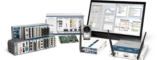
A Virtual Instrumentation system consists of three main components:
Data Acquisition (DAQ) Hardware – Collects real-world signals from sensors and converts them into digital data.
Software (Graphical or Programming-Based Interface) – Processes and analyzes data using platforms like LabVIEW, MatDeck, or Python.
PC or Embedded System – Runs the software and provides visualization through dashboards and graphs.
Key Features of Virtual Instrumentation
✔ Customizable & Scalable – Users can design specific measurement and automation systems tailored to their needs. ✔ Multi-Sensor Integration – Connects multiple devices such as sensors, transducers, and controllers. ✔ Real-Time Data Processing – Provides instant signal analysis and control feedback. ✔ Graphical User Interface (GUI) – Interactive visual elements for monitoring and control. ✔ Cost-Effective – Eliminates the need for multiple physical instruments, reducing expenses.
Applications of Virtual Instrumentation
Virtual Instrumentation is widely used across multiple industries, including:
1. Engineering & Industrial Automation
Real-time monitoring of temperature, pressure, and vibration in manufacturing plants.
Automation of quality control and testing procedures in production lines.
Control of robotic and embedded systems in smart factories.
2. Scientific Research & Laboratories
Physics and chemistry experiments requiring precise measurements.
Environmental monitoring for air and water quality analysis.
Biomedical research involving signal processing for healthcare innovations.
3. Automotive & Aerospace Testing
Performance testing of engines, braking systems, and fuel efficiency.
Aircraft sensor calibration and diagnostics for safety compliance.
Simulation of space missions and satellite telemetry systems.
4. Healthcare & Medical Devices
Patient monitoring systems for tracking heart rate, blood pressure, and ECG.
Medical imaging and diagnostics using signal processing algorithms.
Automated lab equipment for drug testing and bioinformatics research.
Virtual Instrumentation with MatDeck
MatDeck provides an advanced virtual instrumentation environment, offering tools for:
✔ Data Acquisition & Signal Processing – Supports multiple DAQ hardware like Advantech, ICP DAS, and LabJack. ✔ SCADA & Remote Monitoring – Control industrial processes through real-time dashboards. ✔ No-Code Drag & Drop GUI Development – Create custom instrumentation panels with minimal programming. ✔ AI & Machine Learning Integration – Automate data analysis using artificial intelligence models.
Advantages of Virtual Instrumentation Over Traditional Instruments
FeatureVirtual InstrumentationTraditional InstrumentsCustomization✅ Highly flexible❌ Fixed functionalityScalability✅ Expandable & modular❌ Limited to specific tasksReal-Time Analysis✅ Instant data processing❌ Requires external analysisCost-Effectiveness✅ Lower cost, fewer physical devices❌ Expensive standalone instrumentsRemote Access✅ Accessible from any location❌ On-site only
Conclusion
Virtual Instrumentation is transforming the way we measure, analyze, and automate processes across industries. By integrating hardware, software, and real-time data processing, it enhances accuracy, efficiency, and cost-effectiveness in research, engineering, and automation.
With platforms like MatDeck, LabVIEW, and Python, businesses and researchers can develop customized, scalable, and intelligent instrumentation solutions, paving the way for a smarter and more connected world.
0 notes
Text

Defects in PCBs, which are ubiquitously used in all equipment today, can lead to equipment malfunction or even failure. The PCB as a whole needs to be inspected and thoroughly tested for any manufacturing defects. We bring you the #FunctionalATE from #Teradyne to perform comprehensive testing on the following types of PCBs or sections of PCBs: - Power supply - Digital sections - Analogue sections - Mixed signal - Communication/interface - Display - RF - Boundary Scan - Open/short circuits The #ATE uses instruments such as PXI/PCIe/PCI, VXI, LXI, and those with USB/RS-232/Ethernet and other interfaces. It uses software in Microsoft Visual Studio, Microsoft .NET, National Instruments #LabVIEW and Test Stand, and Teradyne CSi instrumentation. For More Info: https://zurl.co/cou9
0 notes
Text
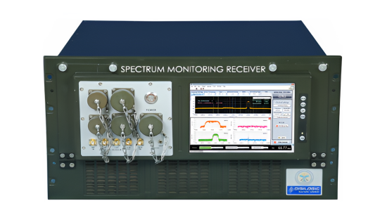
Spectrum Monitoring Receiver from Digilogic Systems
Introduction:
In today’s increasingly complex RF environments, efficient and precise spectrum monitoring is essential. Spectrum monitoring is a critical process in managing and optimizing the use of radio frequencies across various applications, including telecommunications, aerospace, and defence. By continuously observing the radio frequency spectrum, spectrum monitoring ensures compliance with regulatory standards, identifies unauthorized transmissions, and detects potential interference sources.
Advanced Spectrum Monitoring Receiver systems utilize advanced technologies to analyze real-time frequency data, ensuring reliable performance and preventing service disruptions, safeguarding the spectrum, and enhancing communication infrastructure.
What is spectrum monitoring?
Spectrum monitoring is performed by utilizing up-to-date highly integrated PXIe-based systems to demodulate and analyse digital and analog RF/IF signals. These systems which have been created in LabVIEW and utilizing Virtex- 5 FPGA technology, can acquire up to six signals from NI PXIe monitoring receivers.
Some of these figures include the spectrum and small satellite mapping, the use of Waterfall/Spectrogram real-time probe, and RAID for post-analysis. Operations like ‘channelizing’ and ‘demodulation’ facilitate fine-tuning and selective filtering and decoding of the signals according to the characteristics set by the user.
Why is spectrum monitoring important?
Spectrum Monitoring Importance
Detects interprets, and successfully controls radio communication frequency signals.
Promotes proper use of the available spectrum and identifies those who are using the frequency without authority.
Reduced interference of the communications that are central to the functioning of the system.
Uses such interfaces as panoramic spectrum displays and spectrograms in real-time.
Helps in meeting the requirements of the laws, and aids in efficient spectrum management and coordination in case of an emergency.
Maintains the cleanliness of the communication networks.
Includes processing capabilities of the channelization and demodulation for targeted signal control.
How does Digilogic Systems spectrum monitoring work?
Signal Acquisition: Several RF/IF signals are received through the NI PXIe monitoring receivers.
Digital Down conversion: In the receiver path the received signals are down converted to a lower frequency to allow easy digital processing.
Channelization: The signals that are down converted are further partitioned into six independent paths for parallel processing.
Signal Analysis: Regarding the signal acquired in each channel, signal processing is applied by utilizing numerous methods on LabVIEW.
Visualization: Spectrum and waterfall are typical types of displays that give immediate information regarding signals.

What technologies are used in Digilogic Systems spectrum monitoring systems?
Spectrum monitoring systems of Digilogic Systems are designed using PXIe architecture, LabVIEW software, and Virtex-5 FPGA for effective signal analysis. These include live images of the panoramic spectrum, spectrogram displays, and recording/playback functionalities. Sophisticated channelizing and demodulation allow for processing up to six signals at a time with separate bandwidth settings.
What are the key applications of Digilogic Systems spectrum monitoring?
The main use is found in the areas of communications such as telecommunication, aerospace, and defence to the set legal requirements. Frequency supervision aids in
The administration and identification of unauthorized uses as well as signal jamming in those sectors of operation.
Potential Applications
Signal Intelligence: Gathering intelligence from intercepted exchanges using voice or digital media.
Radar Signal Processing: Interpreting the signals for identification and tracking of targets through radar.
Communications System Development and Testing: Assessment of communication systems and their overall performance.
Electronic Warfare: Identifying and categorizing the hostile signals.
How does Digilogic Systems spectrum monitoring help with regulatory compliance?
Digilogic’s Spectrum monitoring ensures that users adhere to regulatory standards by identifying unauthorized transmissions and potential interference sources. This helps regulatory bodies enforce spectrum policies and manage frequency allocations effectively.
Features:
Real-time digital IF data acquired by Spectrum Monitoring Receiver.
Real-time analog IF data digitized via high-speed digitizer
High-performance Virtex-5 FPGAs for processing
Spectrum and Waterfall representation
Signal recording & replaying on/from RAID
Processing of multiple signals (up to 6 signals in a total span of 50 MHz of bandwidth)
Manual demodulation of each signal (up to 20 MHz of bandwidth)
Facts:
Monitoring of complete signal scenarios.
Powerful classifier & extensive signal processing library with demodulators.
Configurable detection of fixed frequency & burst with the processing of the detected signal.
Modular capability of selecting from one channel through a six-channel signal processing solution.
Open interface for independent extension of signal processing capabilities of the user.
Signal recording & replaying on/from Solid Disk Drive.
Conclusion:
The Spectrum Monitoring Analyser of the Digilogic System is an efficient and multifunctional device for performing various types of RF/IF signal analysis. The use of PXIe as the basis for the system together with being integrated with LabVIEW software and Virtex-5 FPGA provides signals’ high-quality processing. As the system can handle up to six signals at a time, this means that the variety of waveforms is encompassed by the system.
The ability to analyze signal characteristics in a real-time waterfall and panoramic spectrum display is also very useful. In addition, the recording and replay function prepared for offline examination is particularly useful in this regard. Because users can alter the parameters of channelization and demodulation, it becomes possible to derive usable information from the received signal. In summary, Digilogic’s analyzer is a valuable tool for researchers and engineers who are solving problems in the RF and communications fields.
Contact us today to discuss your Spectrum Monitoring requirements:
Website: https://www.digilogicsystems.com/
Phone:
Hyderabad: (+91) 40 4547 4601 / 02 / 03
Bengaluru: (+91) 80 4975 6034
Email: [email protected]
Locations:
HEAD OFFICE
#102, 1st Floor, DSL Abacus Tech Park beside DSL Virtue Mall, Uppal, Hyderabad, Telangana-500 039.
BRANCH OFFICE
#216, 3rd floor, Zareen Heights, Varthur Road, Nagavarapalya, C. V. Raman Nagar, Bengaluru, Karnataka — 560093.
0 notes
Text
LabVIEW Data Acquisition System
Data acquisition is a critical aspect of various industries, from scientific research to industrial automation. LabVIEW, developed by National Instruments, offers a powerful platform for designing and implementing data acquisition systems efficiently. In this article, we'll delve into the intricacies of LabVIEW data acquisition systems, exploring their components, setup, programming, benefits, applications, case studies, challenges, and future trends.
Introduction to LabVIEW Data Acquisition System
Understanding Data Acquisition Systems
Data acquisition systems are instrumental in collecting and processing data from physical phenomena or systems. These systems typically consist of sensors, signal conditioning hardware, and software for data processing and analysis.
Importance of LabVIEW in Data Acquisition
LabVIEW stands out as a premier software tool for data acquisition due to its user-friendly graphical programming interface and extensive library of functions for signal processing, analysis, and visualization.
Components of a LabVIEW Data Acquisition System
Hardware Components
A LabVIEW data acquisition system comprises various hardware components, including sensors, signal conditioning modules, data acquisition devices (DAQ), and interfaces for connecting with external devices.
Software Components
LabVIEW software provides the programming environment for configuring, controlling, and monitoring data acquisition processes. It offers a wide range of built-in functions and libraries for seamless integration with hardware components.
Setting Up a LabVIEW Data Acquisition System
Installation Process
Setting up LabVIEW involves installing the software on a compatible computer system and configuring it to communicate with the hardware components of the data acquisition system.
Configuring Hardware
Once the software is installed, users need to configure the hardware components by selecting appropriate drivers and setting up communication protocols within the LabVIEW environment.
Programming in LabVIEW for Data Acquisition
Basics of LabVIEW Programming
LabVIEW programming involves creating virtual instruments (VIs) using a graphical programming language known as G, which utilizes a block diagram approach for visual representation of code.
Data Acquisition Techniques
LabVIEW offers various data acquisition techniques, including analog and digital input/output, voltage measurements, frequency measurements, and waveform generation, all of which can be implemented through intuitive programming constructs.
Benefits of Using LabVIEW for Data Acquisition
Versatility and Flexibility
LabVIEW provides a versatile and flexible platform for designing custom data acquisition systems tailored to specific application requirements.
Integration with Other Systems
LabVIEW seamlessly integrates with other systems and software tools, allowing for interoperability and compatibility with existing infrastructure.
Scalability and Customization
LabVIEW offers scalability, enabling users to expand their data acquisition systems as per evolving needs, along with extensive customization options for optimizing performance.
Applications of LabVIEW Data Acquisition System
Industrial Automation
LabVIEW data acquisition systems find extensive applications in industrial automation for monitoring and controlling processes in manufacturing, quality assurance, and product testing.
Scientific Research
In scientific research, LabVIEW facilitates data collection and analysis in diverse fields such as physics, chemistry, biology, and environmental science, enabling researchers to conduct experiments and gather insights efficiently.
Medical Monitoring
LabVIEW-based data acquisition systems play a crucial role in medical monitoring applications, including patient monitoring, diagnostic equipment, and biomedical research, aiding in the advancement of healthcare technologies.
Environmental Monitoring
LabVIEW is utilized for environmental monitoring tasks such as weather forecasting, pollution detection, and ecological research, contributing to the preservation and sustainability of natural resources.
Case Studies: Real-World Implementations
Case Study 1: Automotive Testing
LabVIEW data acquisition systems are employed in automotive testing facilities for evaluating vehicle performance, conducting crash tests, and analyzing vehicle dynamics under various conditions.
Case Study 2: Weather Monitoring
Meteorological agencies utilize LabVIEW-based data acquisition systems for collecting and analyzing weather data, including temperature, humidity, wind speed, and precipitation, to forecast weather patterns accurately.
Case Study 3: Biomedical Research
In biomedical research laboratories, LabVIEW facilitates the acquisition and analysis of physiological data, imaging data, and genetic data, supporting advancements in disease diagnosis, treatment, and drug development.
Challenges and Solutions in LabVIEW Data Acquisition
Compatibility Issues
One challenge in LabVIEW data acquisition is compatibility issues between hardware components and software versions, which can be mitigated through careful selection and configuration of compatible components.
Data Processing Challenges
Processing large volumes of data in real-time poses another challenge, requiring efficient algorithms and hardware optimization techniques to ensure timely and accurate data acquisition and analysis.
Calibration and Maintenance
Regular calibration and maintenance of hardware components are essential to maintain the accuracy and reliability of LabVIEW data acquisition systems, requiring adherence to best practices and standards.
Future Trends in LabVIEW Data Acquisition
Advancements in Hardware Technology
Future advancements in hardware technology, such as faster processors, higher-resolution sensors, and wireless connectivity, will enhance the performance and capabilities of LabVIEW data acquisition systems.
AI Integration
Integration of artificial intelligence (AI) algorithms into LabVIEW data acquisition systems will enable predictive analytics, anomaly detection, and autonomous decision-making, revolutionizing data acquisition processes.
IoT Integration
LabVIEW data acquisition systems will increasingly integrate with the Internet of Things (IoT) ecosystem, leveraging cloud computing, edge computing, and wireless sensor networks for enhanced connectivity, scalability, and interoperability.
Conclusion
LabVIEW data acquisition systems offer a comprehensive solution for collecting, processing, and analyzing data across various industries and applications. With its user-friendly interface, robust functionality, and versatility, LabVIEW continues to empower engineers, researchers, and scientists in their quest for innovation and discovery. If you want to read more blogs/articles so visit on PujaControls
#automation#labview#technology#software development#iot#iot integration#ai integration#automotive testing#industrial automation
0 notes
Video
youtube
IOT Based Industrial Air Pollution Monitoring System using Arduino with LabVIEW and Zigbee on Thingspeak | iot based air pollution monitoring system using arduino | IoT Projects using ESP32 | IoT Projects Arduino | WSN Based Real Time Air Pollution Monitoring System Using Zigbee and LabVIEW | Industrial Monitoring System using LabVIEW and GSM.***********************************************************If You Want To Purchase the Full Working Project KITMail Us: [email protected] Name Along With You-Tube Video LinkWe are Located at Telangana, Hyderabad, Boduppal. Project Changes also Made according to Student Requirementshttp://svsembedded.com/ https://www.svskits.in/ http://svsembedded.in/ http://www.svskit.com/M1: 91 9491535690 M2: 91 7842358459 We Will Send Working Model Project KIT through DTDC / DHL / Blue Dart / First Flight Courier ServiceWe Will Provide Project Soft Data through Google Drive1. Project Abstract / Synopsis 2. Project Related Datasheets of Each Component3. Project Sample Report / Documentation4. Project Kit Circuit / Schematic Diagram 5. Project Kit Working Software Code6. Project Related Software Compilers7. Project Related Sample PPT’s8. Project Kit Photos9. Project Kit Working Video linksLatest Projects with Year Wise YouTube video Links157 Projects https://svsembedded.com/ieee_2022.php135 Projects https://svsembedded.com/ieee_2021.php 151 Projects https://svsembedded.com/ieee_2020.php103 Projects https://svsembedded.com/ieee_2019.php61 Projects https://svsembedded.com/ieee_2018.php171 Projects https://svsembedded.com/ieee_2017.php170 Projects https://svsembedded.com/ieee_2016.php67 Projects https://svsembedded.com/ieee_2015.php55 Projects https://svsembedded.com/ieee_2014.php43 Projects https://svsembedded.com/ieee_2013.php1100 Projects https://www.svskit.com/2022/02/900-pr...***********************************************************Creating an IoT-based Industrial Air Pollution Monitoring System using Arduino with LabVIEW and Zigbee on ThingSpeak involves integrating various components and technologies. Here's a step-by-step guide to help you get started:Components Needed:1. Arduino Board (e.g., Arduino Uno):• Used for sensor interfacing and data processing.2. Air Quality Sensors (e.g., MQ series sensors):• Measure air pollution parameters like CO, CO2, particulate matter, etc.3. Zigbee Module:• Enables wireless communication between Arduino and the central system.4. LabVIEW Software:• Used for creating a graphical user interface (GUI) and processing data.5. ThingSpeak Account:• Online platform for storing and analyzing sensor data.Hardware Setup:1. Connect Air Quality Sensors to Arduino:• Wire the sensors to the analog or digital pins on the Arduino.2. Connect Zigbee Module to Arduino:• Use UART communication to connect the Zigbee module to the Arduino.3. Power Supply:• Ensure that all components have a stable power supply.4. Configure Zigbee Communication:• Set up Zigbee communication between the Arduino and the central system.Software Implementation:1. Arduino Programming:• Write a program to read sensor data and send it to the Zigbee module.• Implement error handling and data formatting.2. LabVIEW GUI Design:• Create a LabVIEW VI (Virtual Instrument) for the user interface.• Add indicators to display real-time sensor data.• Implement controls for system configuration.3. LabVIEW Serial Communication:• Use LabVIEW to establish serial communication with the Arduino through the Zigbee module.• Implement data parsing to extract sensor values.4. ThingSpeak Integration:• Create a ThingSpeak channel to store the sensor data.• Use the ThingSpeak API in LabVIEW to send data to ThingSpeak.Data Visualization:1. LabVIEW Visualization:• Use LabVIEW to create charts, graphs, or other visual representations of air pollution data.2. ThingSpeak Dashboard:• Explore ThingSpeak's built-in tools for data visualization and analysis.Testing and Debugging:1. Test the System:• Ensure that the hardware connections are secure.• Check data transmission between Arduino and LabVIEW.• Verify data upload to ThingSpeak.2. Debugging:• Use serial monitoring tools for Arduino to debug communication issues.• Check LabVIEW code for any errors or unexpected behavior.Finalization:1. Optimization:• Optimize the code for efficiency and reliability.• Consider implementing features like data logging or notifications.2. Documentation:• Document the system architecture, hardware connections, and software implementation.3. Deployment:• Install the system in the industrial environment.• Monitor and maintain the system as needed.By following these steps, you can create a robust IoT-based Industrial Air Pollution Monitoring System using Arduino, LabVIEW, Zigbee, and ThingSpeak.
0 notes
Text
Get ahead of testing challenges with the Moku Lock-in Amplifier from Liquid Instruments
Are you tired of spending countless hours using legacy test equipment for your measurements and experiments? Do you wish there was a simpler way to achieve accurate results in less time? Look no further than the Moku Lock-in Amplifier from Liquid Instruments, a flexible, software-driven instrument that will revolutionize the way you test.
Why choose the Moku Lock-in Amplifier?
The Moku Lock-in Amplifier is a powerful tool that offers a range of resources to help you work smarter and achieve more. With advanced features and an intuitive interface, this flexible instrument is designed to simplify your workflow and enhance your productivity.
Enhanced accuracy
One of the standout features of the Moku Lock-in Amplifier is its exceptional accuracy. Whether you're measuring small signals in noisy environments or conducting complex experiments, this device delivers precise results every time. Say goodbye to unreliable data and hello to accurate measurements.
Versatility at its best
The Moku Lock-in Amplifier is no one-trick pony. It offers best-in-class flexibility for top performance in a wide range of applications, making it perfect for researchers, scientists, and engineers in various fields. From materials science and quantum computing to photonics and spectroscopy, this instrument has you covered.
Intuitive user interface
Liquid Instruments understands that ease of use is paramount for productivity. That’s why the Moku Lock-in Amplifier comes with a modern, highly intuitive block-diagram user interface that allows you to set up and control your measurements effortlessly. Spend less time fumbling with complex instrument settings and more time focusing on what matters — advancing your research.
Seamless integration
The Moku Lock-in Amplifier seamlessly integrates with other devices and software, making it a versatile addition to your lab. This powerful, software-defined instrument is compatible with Python, LabVIEW, and MATLAB, so you can easily automate your experiments and analyze your data. With the Moku Lock-in Amplifier, you can streamline your workflow and achieve more with less.
Unleash the power of the Moku Lock-in Amplifier: A versatile instrument for deeper insights
Performing complex measurements with confusing and counterintuitive test equipment can stall or halt research progress. Modern test instruments, such as the Moku Lock-in Amplifier, provide a multi-purpose platform to handle signal capture, transmission, data logging, and more.
What is a lock-in amplifier?
Before we dive into the capabilities of the Moku Lock-in Amplifier, let’s review why a lock-in amplifier is important. A lock-in amplifier is a versatile instrument commonly used in scientific research and engineering applications. It is designed to extract weak signals from noisy backgrounds, making it ideal for detecting small signals in the presence of noise.
Introducing the Moku Lock-in Amplifier
The modern, software-defined Moku Lock-in Amplifier is a game-changer in the world of lock-in amplifiers. It is easy to use and offers a range of advanced capabilities to optimize your experiment — at the most cost-effective price in the industry. It is available on all Moku devices: Moku:Pro, Moku:Lab, and Moku:Go. This means you can choose the device with the specifications that best suit your needs and still enjoy the flexibility and performance of the Moku Lock-in Amplifier.
Unparalleled versatility
One of the standout features of the Moku Lock-in Amplifier is its versatility. It offers a wide range of features that go beyond traditional lock-in amplifiers. Let's take a closer look:
Built-in Data Logger
Gone are the days of relying on external data acquisition and data loggers to record your measurements. The Moku Lock-in Amplifier comes with a built-in Data Logger that allows you to easily capture and analyze your measurements, helping you maximize time savings while reducing the clutter on your lab bench.
Integrated Oscilloscope
With the Moku Lock-in Amplifier, you don't need a separate device to visualize your signals. You can monitor up to four signals at a time using the fully integrated four-channel, 1.25 GSa/s Oscilloscope.
0 notes
Text
Empowering Seamless Hardware Integration And Custom Application
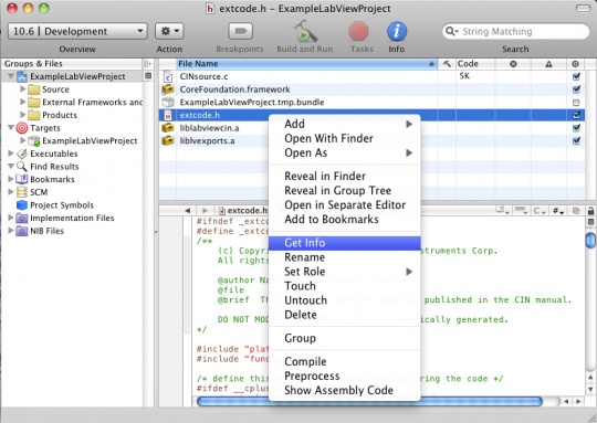
LabVIEW (Laboratory Virtual Instrument Engineering Workbench) is a popular software development environment used for creating applications that interface with hardware devices and systems. To know more Labview interface you should kingstar to get more detailed information. Don't hesitate to contact us at @ 781- 209 -2810.
For more info visit:
https://help.kingstar.com/tutorials/HTML5/Installing_KS_SM_HTML5/Content/2019_01_KS_SM_Tutorial/ManuallyAssociateNIC.htm
0 notes
Text
Drivers Coretech Laptops & Desktops

You CAN install current versions of ActiView on Windows 10. But, before you do so, if the system was orignally delivered before January of 2017 you should update the firmware on the optical receiver / USB interface so that you do not have to go through the very long and arduous process of installing an unsigned driver on Windows 10.

Drivers Coretech Laptops & Desktops Best Buy
You can update the firmware using any Windows 7 or 8 computer with the MSWinUSB2 driver installed, even if it is not the computer you have been using for ActiView. If you are just using a Windows 7 or 8 computer to update firmware on the optical receiver / USB interface, there is no need to install the LabVIEW Runtime Engine or ActiView on this computer. You WILL need the LabVIEW Runtime Engine and ActiView on the new Windows 10 computer, but you WILL NOT need to install a driver after the firmware update has been performed.

See the procedure outlined at biosemi.com/ faq/install_USB.htm for detailed instructions. The section at the bottom marked IMPORTANT is the place to begin.

Drivers Coretech Laptops & Desktops
Issues can occur when you first start the software, or may be due to a driver or Windows update. If you previously had a working configuration, consider rolling back the driver version or restoring Windows to a working restore point. Some laptops have both a dedicated graphics processor and an integrated processor. Download “CoretechSCCMManager1.0.4.zip” CoretechSCCMManager1.0.4.zip – Downloaded 4296 times – 1 MB This week a customer contacted us, claiming that the tool did not work on sundays! I thought that was pretty strange, so I asked for log file/event log messages, and it was true.
Drivers Coretech Laptops & Desktops Reviews
For anyone working with OSD for more than about 4 minutes, you know that its in the WinPE phase most of the magic happens. For testing and troubleshooting purposes its quite helpful to add some tools to your boot image, so you always have them available without having to download from a web server or.
2 notes
·
View notes
Text
Labview 2018 For Mac Os
Ni Labview 2018 Control Design And Simulation Module (x86/x64) Simulation is a process that involves using software to recreate and analyze the behavior of dynamic systems. You use the simulation process to lower product development costs by accelerating product development. Windows Installation Instructions (click to expand) Download LabView using the link provided. Click OK, accepting English as the language. Click Unzip to extract the files. At the UAC, Click Yes. Install.Net Framework 4. At the Welcome Screen, click Next. Enter Full Name and Organization and click Next. Select “Mac OS X 10.6” from the “Base SDK” sub-section. Double click “Valid Architectures” and change it to “i386”. Step 4: Add the Exodriver to the linker flags. How to install LabVIEW for mac. This guide explains how to install and activate LabVIEW for mac. This guide explains how to install and activate LabVIEW for mac downloaded from swdb.ucl.ac.uk. LabVIEW 8.0 Readme for Mac OS X. October 2005. This file contains important last-minute information about LabVIEW 8.0 for Mac OS X, including installation and upgrade issues, compatibility issues, and changes from LabVIEW 7.1.
New Mac Operating System 2018
Mac Os 2018 Release
Latest Mac Os Update 2018
Pes 2018 For Mac Os
Latest Version Of Mac Os 2018
GOM Player 2020 for Mac OS Download
GOM Player 2020 for Mac OS Download – GOM Player for Mac is a functional media player that’s easy to use and looks great. It’s free, plays the most popular video styles, and takes in couple of sources.
Integrated codec: GOM Player plays all preferred video formats. It integrates a few of one of the most vital video clip codecs, like XviD, DivX, FLV, MP4, AVI and also MOV, to name a few.
GOM Player 2020 for Mac OS Review
If you’re tired of mistakes that appear when playing data on your pc currently you will certainly have very easy with GOM Player due to the fact that it is a very total player for all sort of video clips.
GOM Player 2020 for Mac OS permits us to play all the video clips we carry our Mac without any mistake due to the kind of style due to the fact that it is compatible with the majority of the styles that are utilized today. Additionally, GOM Player is really easy to use because consists of all the needed codecs and prevents needing to search by hand.
New Mac Operating System 2018
GOM Player 2020 for Mac OS is designed with a great interface, which supplies all the options of this sort of software program that can be made use of in a really quick and also straightforward method. From now on we will not waste time looking for codecs, just need to download GOM Player as well as we will have the perfect player for all video types we have to reproduce on our Mac. Additionally, GOM Player enables us to do all the screenshots we desire, so it has turned into one of one of the most total programs we could have on our Mac.
PROS
Video clip player with integrated codecs
Noteworthy design as well as usability
Consists of synchronization alternatives
Flexible zoom and also element ratio
It can catch screenshots
Mac Os 2018 Release
CONS
Latest Mac Os Update 2018
Few innovative features
Less alternatives compared to the Windows version
GOM Player 2020 for Mac OS free Download
Pes 2018 For Mac Os
Download Here gom.pkg | Gom Player 2020 Free Download Filehippo
Latest Version Of Mac Os 2018
OS: Windows All
1 note
·
View note
Text
Projet Kart 2020

Mon binôme et moi avons récupérer le projet du Kart.
Ce projet consiste à récupérer des données précises d’un kart électrique, fabriqué par le groupe C1, de les envoyer sur des écrans au sein du kart mais aussi de les envoyer à un PC fixe dans l’IUT qui jouera le rôle de paddock.
En quoi consiste le projet ?
Comme dit précédemment le but premier du projet est de récupérer des données précises sur un kart électrique et de les transmettre sur un PC et des écrans présents dans le kart.
Comme tout projet, on nous impose des spécifications :
Fonctionnelles : on doit pouvoir mesurer en temps réel,transmettre les données et les sauvegarder dans une carte SD présente sur la carte Arduino MEGA.
Opératoires : on doit mesurer de manière automatique la vitesse,le niveau de batterie,la consommation et les températures du moteur,de la batterie et du variateur. On affiche ensuite la vitesse,le niveau de batterie et l’autonomie restante sur des écrans.Et pour les températures, on se servira des Leds RGB (par exemple la Led moteur s’éclaire en vert alors la température moteur est bonne). Pour l’envoi des informations, cela se fera par radiofréquences.
Technologiques : on nous impose une alimentation par pontage sur les batteries du kart (4x24V) pour faire fonctionner notre système.Dans les posts précédents, nous avons décrits tous les compsants nécessaires,il faudra donv nous-mêmes concevoir une carte électronique pour alimenter les capteurs.Enfin, pour réaliser notre projet, nous devons utiliser Eagle,Arduino et LabVIEW et nous aurons forcément besoin du kart réalisé par le groupe C1.

Lors de cette séance, nous avons reçu une boite avec du matériel à l’intérieur. Voici la liste des composants:
Cartes Arduino
On possède 2 cartes Arduino : une UNO et une MEGA.
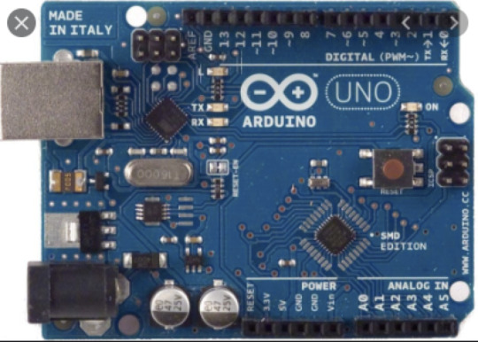

La carte MEGA sera installée directement dans le kart et son rôle sera de réceptionner les données, les envoyer aux écrans dans le kart mais aussi de les envoyer via des ondes radio au paddock (UNO).
La carte UNO devra réceptionner les données de la carte MEGA et les afficher en temps réel sur une interface LabVIEW.
On aura donc 1 antenne radio sur chaque carte Arduino.On aura donc besoin du logiciel Arduino et de LabVIEW pour réaliser notre projet.
LM35 + iduinoST1147 :
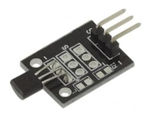
C’est un capteur de température.
OPB 704

C’est un capteur photoélectrique qui permet de mesurer la vitesse.
- Transistor bipolaire: ON semi-conducteur
- Grove - Voltage divider

Il fournit une interface pour mesurer la tension externe, éliminant le besoin de connecter une résistance à l'interface d'entrée. En outre, le gain de tension peut être sélectionné par commutateur à cadran. Ils sont faciles à utiliser.
- LM311N:

Le LM311N est un comparateur de tension.Nous en possédons 1.
- L7812CV:

Ce composant est en réalité un transistor qui va nous permettre de réguler la tension.On en possède 3.
- 4 détecteurs de courants: HAS 200-s et HAS 100-s

D’après la fiche technique de ces composants, les 2 types de détecteurs fonctionnent avec une alimentation de 15V.
Le HAS 100 a un courant nominal In=100A et une échelle de mesure à plus ou moins 300A.
Le HAS 200 a un courant nominal In=200A et une échelle de mesure à plus ou moins 600A.
Les 2 types de détecteurs consomment 15mA.
Il faudra faire attention car si ces appareils fonctionnent pour une tension entre 12V et 15V, cela réduira la précision de leurs mesures.
Voici le lien de la fiche technique des ces capteurs de courant :
http://www.farnell.com/datasheets/3047882.pdf
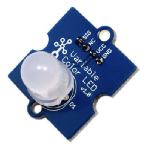
- 3 led RGB - Grove:
- 2 écrans LCD
- Condensateurs:
100n J63
100n K63
2x 100n M63
4 x 10nK 63
10nnK63
10 uF , 35V gif censa
- 1 potentiomètre 4700 Ohm
- Résistances (Ohm):
120k
100k
6800
2200
220
3,3k
470k
2700
- Diodes:
On a d’abord une diode 1N5818-734 et une diode 1N5818-444Y : ce sont des diodes de redressement.
On en ensuite une diode 4004 qui est une diode de puissance capable de supporter une tension inverse de 400V
Fiche technique des diodes :
pdf.datasheetcatalog.net/datasheet/fairchild/1N5818.pdf
https://docs.rs-online.com/3048/0900766b8137d734.pdf
- horloge temps réel:

Permet de récupérer les valeurs en temps réel.
1 note
·
View note
Text
MatDeck: A Powerful All-in-One Software for Engineering, AI, and Data Analysis
In today’s fast-paced technological world, professionals across various fields require powerful, versatile, and efficient software to handle tasks like data analysis, engineering simulations, AI modeling, and scientific computing. MatDeck is an innovative, all-in-one software platform that integrates mathematics, programming, AI, data acquisition, and graphical user interface (GUI) development into a single environment. Whether you are a scientist, engineer, researcher, or developer, MatDeck offers a seamless workflow for your computational needs.
What is MatDeck?
MatDeck is a high-performance software suite designed for data analysis, engineering, AI modeling, simulation, and automation. It combines features from MATLAB, Python, and LabVIEW, providing users with an intuitive interface and powerful computational capabilities. The software supports scientific programming, GUI development, signal processing, AI/ML applications, and hardware integration.
Key Features of MatDeck
1. Advanced Mathematics & Scientific Computing
MatDeck offers a comprehensive set of mathematical tools, including:
Algebraic and symbolic computation
Matrix operations and vector calculus
Differential equations and integrals
Probability distributions and statistical analysis
2. Programming Capabilities (Python & MD Script)
MatDeck supports Python integration, allowing users to execute Python scripts directly within its environment. It also includes MD Script, a unique scripting language optimized for high-performance computations.
3. Artificial Intelligence & Machine Learning
Built-in support for TensorFlow and PyTorch
No-code AI model creation
Data visualization and predictive analytics
Image processing and deep learning applications
4. Data Acquisition & Hardware Integration
Compatible with 400+ hardware devices (Advantech, ICP DAS, LabJack, etc.)
Supports Modbus, SCADA, and virtual instrumentation
Real-time sensor data acquisition and control
5. Graphical User Interface (GUI) Designer
Drag-and-drop GUI development with no coding required
Supports Tkinter, PyQt, and Flet for Python applications
Interactive dashboards for real-time monitoring and data visualization
6. Engineering & Simulation Tools
Circuit design and analysis
Finite Element Analysis (FEA)
DSP (Digital Signal Processing) & Fast Fourier Transform (FFT)
Automation and control system modeling
7. Document-Based Workflow
Unlike traditional programming environments, MatDeck uses interactive document-based workflows, allowing users to combine:
Code execution
Data visualization
Mathematical equations
Embedded simulations
Applications of MatDeck
✔ Engineering & Robotics – Automate control systems and real-time simulations. ✔ AI & Machine Learning – Train deep learning models and deploy AI applications. ✔ Scientific Research – Solve complex equations and visualize experimental data. ✔ Data Acquisition & IoT – Connect hardware devices for real-time monitoring. ✔ Software Development – Create standalone GUI-based applications.
Conclusion
MatDeck is a powerful, feature-rich platform that bridges the gap between mathematical computing, AI, and software development. Its versatility, ease of use, and integration capabilities make it an essential tool for engineers, data scientists, and researchers looking to enhance productivity and streamline their workflow.
0 notes
Text
TPS App breakdown
I need to get this out in the ether because I know at some point i will completely forget what I wrote so here it goes.
This front end of this application is a simple graphical user interface written in HTML, CSS, and some Javascript.

the most important part of this front end is in the javascript where, when a button is pressed, some attributes of the button are changed, most importantly the name.
The back end part of the App is written in javascript where I essentially have a main loop continuously check to see if a button is clicked by checking the name attribute of each button . I feel like this is a pretty sloppy way of doing button commands via a GUI and that doing it purely in tkinter or even labview might be better, but when I started this project I thought I could do the whole thing with just selenium and javascript node.js but I quickly realized how much of a pain thatd be. Also I knew that python had a library that could build an executable extremely easily so I went with python, but I digress.
Lets say that one of the top 3 rectangle buttons were clicked. I would catch the name change with my loop. Each one of these buttons represented a scene in a media app. For example “instructor only” is a scene that contains only a feed of an auto tracking camera, “Instructor and projector” is a scene where a picture in picture of the camera feed with the projector, both of which are fed into SDI slots in the back of an automate select. More on this later, actually screw it we’ll do this now.
Pause from the code and lets get into the hardware. The goal of the project was to be able to produce high quality recordings of lectures for students to use for studying, missed classes, etc. Since this was for the world famous USAF Test Pilot School, they spared no expense. So the proposed solution was to get two extremely good auto tracking cameras, equipped with a control box and we had to fit it into the existing system.
The system in place was fairly simple. A professor would put a powerpoint on his/her computer which would display on 1 of 3 screens. Each one of these screens would also display a respective projector so that the students could see. Also the feeds of the screens would split to another piece of hardware that we don’t really care about.
The camera control hardware was also responsible for recording the lectures as well. However it was designed to be used for two cameras and a projector feed in 1 classroom, not two.
Anyways. In order to cycle through the projector feeds so that the correct screen gets recorded on the control hardware we installed a programmable Kramer switch that can accept three inputs and output one.
Well this is all the time I have for right now. Time to GTFO and go home!
1 note
·
View note
Text
Ubidots + ESP32- Predictive Machine Monitoring
Predictive analysis of machine vibration and temp by creating mail events and a record of vibration in google sheet using Ubidots.

Story
Predictive Maintenance and Machine Health Monitoring
The rising of new technology i.e, the Internet of Things, heavy industry has started adopting sensor-based data collection to solve its biggest challenges, principal among them process downtime in the form of shutdowns and process delays. Machine monitoring also called predictive maintenance or condition monitoring is the practice of monitoring electrical equipment through sensors in order to accumulate diagnostic data. To achieve this, data acquisition systems and data loggers are used to monitor all kinds of equipment, such as boilers, motors, and engines. Following condition are measured:
Temperature and Humidity Data Monitoring
Current and Voltage Monitoring
Vibration Monitoring: In this article, we will read Temperature, vibration and publish the data in Ubidots. Ubidots supports graphs, UI, notifications, and emails. These features make it ideal for predictive maintenance analysis. We will also get the data in google sheets which will make predictive maintenance analysis more easier.
Hardware:
ESP-32
IoT Long Range Wireless Vibration And Temperature Sensor
Long-Range Wireless Mesh Modem with USB Interface
Software Used:
Arduino IDE
Ubidots
LabView Utility
Library Used:
PubSubClient Library
Wire.h
Arduino Client for MQTT
This library provides a client for doing simple publish/subscribe messaging with a server that supports MQTT
For more information about MQTT, visit mqtt.org.
Download
The latest version of the library can be downloaded from GitHub
Documentation
The library comes with a number of example sketches. See File > Examples > PubSubClient within the Arduino application.Full API Documentation.
Compatible Hardware
The library uses the Arduino Ethernet Client api for interacting with the underlying network hardware. This means it Just Works with a growing number of boards and shields, including:
Arduino Ethernet
Arduino Ethernet Shield
Arduino YUN – use the included YunClient in place of EthernetClient, and be sure to do a Bridge.begin() first
Arduino WiFi Shield - if you want to send packets greater than 90 bytes with this shield, enable the MQTT_MAX_TRANSFER_SIZE () option in PubSubClient.h.
Sparkfun WiFly Shield – when used with this library
Intel Galileo/Edison
ESP8266
ESP32The library cannot currently be used with hardware based on the ENC28J60 chip – such as the Nanode or the Nuelectronics Ethernet Shield. For those, there is an alternative library available.
Wire Library
The Wire library allows you to communicate with I2C devices, often also called "2 wire" or "TWI" (Two Wire Interface), can download from Wire.h
Basic Usage
Wire.begin()Begin using Wire in master mode, where you will initiate and control data transfers. This is the most common use when interfacing with most I2C peripheral chips.
Wire.begin(address)Begin using Wire in slave mode, where you will respond at "address" when other I2C masters chips initiate communication.
Transmitting
Wire.beginTransmission(address)Start a new transmission to a device at "address". Master mode is used.
Wire.write(data)Send data. In master mode, beginTransmission must be called first.
Wire.endTransmission()In master mode, this ends the transmission and causes all buffered data to be sent.
Receiving
Wire.requestFrom(address, count)Read "count" bytes from a device at "address". Master mode is used.
Wire.available()Returns the number of bytes available by calling receive.
Wire.read()Receive 1 byte.
Steps to send data to Labview vibration and temperature platform using IoT long-range wireless vibration, temperature sensor and long-range wireless mesh modem with USB interface:
First, we need a Labview utility application which is ncd.io Wireless Vibration and Temperature Sensor.exe file on which data can be viewed.
This Labview software will work with ncd.io wireless Vibration Temperature sensor only
To use this UI, you will need to install following drivers Install run time engine from here 64bit
32 bit
Install NI Visa Driver
Install LabVIEW Run-Time Engine and NI-Serial Runtime
Getting started guide for this product.
Uploading the code to ESP32 using Arduino IDE:
Download and include the PubSubClient Library and Wire.h Library.
You must assign your unique Ubidots TOKEN, MQTTCLIENTNAME, SSID (WiFi Name) and Password of the available network.
Compile and upload the Ncd__vibration_and_temperature.ino code.
To verify the connectivity of the device and the data sent, open the serial monitor. If no response is seen, try unplugging your ESP32 and then plugging it again. Make sure the baud rate of the Serial monitor is set to the same one specified in your code 115200.
Serial Monitor Output:

Data on serial monitor of Arduino IDE.
Making the Ubidot Work:
Create the account on Ubidot.
Go to my profile and note down the token key which is a unique key for every account and paste it to your ESP32 code before uploading.
Add a new device to your Ubidot dashboard name ESP32.


Now you should see the published data in your Ubidots account, inside the device called "ESP32".
Inside the device create a new variable name sensor in which your temperature reading will be shown.


Now you are able to view the Temperature and other sensors data which was previously viewed in the serial monitor. This happened because the value of different sensor readings is passed as a string and store in a variable and publish to a variable inside device esp32.
Create a dashboard in ubidots.

Go to data select dashboard and inside dashboard create different widgets and add a new widget to your dashboard screen.
OUTPUT
Now as the temperature/vibration increases and decreases new data available inside the various variable.

Creating Events in Ubidots

1) Select Events (from the Data dropdown).

2) To create a new event, click the yellow plus icon in the upper right corner of the screen.
Types of Events: Ubidots support already integrated events to allow you to send Events, Alerts, and Notifications to those who need to know when they need to know. Ubidots' prebuilt integrations include:
Email notifications
SMS notifications
Webhook events - learn more
Telegram notifications
Slack notifications - learn more
Voice Call notifications - learn more
Back to Normal notification - learn more
Geofence notifications - learn more
3) Then choose a device and associating variable that indicates the devices' "values".

4) Now select a threshold value for your event to trigger and compare it to device values and also select time to trigger your event.
5) Establish and configure which actions are to be executed and the message to the receiver: Send SMS, Email, Webhooks, Telegrams, Phone Calls, SLACK, and webhooks to those who need to know.

6) Configure the Event notice.

7) Determine the activity window the events may/may not be executed.

8) Confirm your Events.
The output of Event in Your Mail:

Export Your Ubidots Data to Google Sheets:
In this, we can extract the data stored in the Ubidots cloud for further analysis. The possibilities are enormous; for instance, you could create an automatic report generator and send them to your customers every week.
Another application would be device provisioning; if you have thousands of devices to deploy, and their information is in a Google Sheet, you could create a script to read the sheet and create a Ubidots data source for every line on the file. Steps to do this-
Create a Google Sheet and add two sheets to it with these names:
Variables
Values
From your Google Sheet, click on "Tools" then "Script Editor...", then "Blank Project".
Open the Script Editor.

Add the code below (in the code section) to the script Script.
Done! now open your Google Sheet again and you'll see a new menu to trigger the functions.

Result:

1 note
·
View note