#nodemcu esp32 arduino
Explore tagged Tumblr posts
Visit Tumblr Blog
Explore Tumblr blogs with no restrictions, modern design and the best experience.
Last Seen Tumblr Blogs


Fun Fact
When “GIF” was named word of the year in 2012, Oxford Dictionaries U.S.A. credited Tumblr for pushing the word.
Video
youtube
Smart Waste Management System Using ESP32 | IOT BASED GARBAGE MONITORING SYSTEM | IoT Smart Dustbin : ESP32 - SIM800L - GPS Location | IoT-Based Garbage Container System Using NodeMCU | IoT Cloud Web Server Based Garbage Monitoring System Using ESP32.***********************************************************If You Want To Purchase the Full Working Project KITMail Us: [email protected] Name Along With You-Tube Video LinkWe are Located at Telangana, Hyderabad, Boduppal. Project Changes also Made according to Student Requirementshttp://svsembedded.com/ https://www.svskits.in/ http://svsembedded.in/ http://www.svskit.com/M1: 91 9491535690 M2: 91 7842358459 We Will Send Working Model Project KIT through DTDC / DHL / Blue Dart / First Flight Courier ServiceWe Will Provide Project Soft Data through Google Drive1. Project Abstract / Synopsis 2. Project Related Datasheets of Each Component3. Project Sample Report / Documentation4. Project Kit Circuit / Schematic Diagram 5. Project Kit Working Software Code6. Project Related Software Compilers7. Project Related Sample PPT’s8. Project Kit Photos9. Project Kit Working Video linksLatest Projects with Year Wise YouTube video Links157 Projects https://svsembedded.com/ieee_2022.php135 Projects https://svsembedded.com/ieee_2021.php 151 Projects https://svsembedded.com/ieee_2020.php103 Projects https://svsembedded.com/ieee_2019.php61 Projects https://svsembedded.com/ieee_2018.php171 Projects https://svsembedded.com/ieee_2017.php170 Projects https://svsembedded.com/ieee_2016.php67 Projects https://svsembedded.com/ieee_2015.php55 Projects https://svsembedded.com/ieee_2014.php43 Projects https://svsembedded.com/ieee_2013.php1100 Projects https://www.svskit.com/2022/02/900-pr...***********************************************************1. IoT Smart Dustbin : ESP32 - SIM800L,2. efficient iot based garbage collecting smart dustbin,3. iot based garbage monitoring using Arduino,4. IoT Based Garbage Monitoring System | ESP8266 | Arduino,5. IoT based Smart Waste Management System using Arduino,6. iot based smart dustbin project report,7. iot based garbage monitoring system project report pdf,8. smart dustbin with garbage level monitoring,9. smart garbage monitoring system using blynk,10. iot based garbage monitoring system using Arduino,11. garbage monitoring system using iot,12. iot based garbage monitoring system using arduino project report,13. smart garbage monitoring system using iot ppt,14. IoT Smart Dustbin : ESP32 - SIM800L - GPS Location | Garbage Bin Waste Monitoring System,15. Iot Based Smart Garbage Bin ,16. Smart IoT-based Waste Monitoring System,17. Smart Dustbin With GPS Location,18. IOT BASED SMART GARBAGE MONITORING SYSTEM USING NODEMCU GSM GPS ULTRASONIC,19. Smart Garbage Monitoring System using Internet of Things (IOT),20. GSM Based Smart Dustbin IOT dustbin notifications | IOT garbage monitoring | dustbin level on IOT | using Arduino,21. IoT Cloud Web server Based Garbage Monitoring System,22. DIY Smart Dustbin with garbage level monitoring | IOT based Garbage monitoring system,23. Smart Garbage Monitoring System using Internet of Things (IOT) || smart bin || BIJEN,24. GSM and GPS Based Garbage and Waste Collection Bin Overflow Management System,25. How To Make An Automatic Object Sensing Smart Dustbin - DIY Project,26. How to make Smart Dustbin with Arduino | Arduino Project,27. Top 10 IoT(Internet Of Things) Projects Of All Time | 2023,28. Smart dustbin at home using arduino | Nodemcu projects | DIY,29. HOW TO MAKE GSM BASED SMART DUSTBIN USING ARDUINO,30. Smart Garbage Collecting Truck Using Arduino, GSM, GPS and Internet of Things (IOT),31. SMART DUSTBIN for SMART CITY with SMS Alerts Using Arduino – GSM,32. SMART DUSTBIN WITH LIVE GPS TRACKING AND MONITORING SYSTEM,33. Smart Trash Bin Monitoring System,
0 notes
Text
Nodemcu Esp32
NodeMCU ESP32 is an ESP-WROOM-32 module in breadboard friendly form factor, you can develop your project by using this compact microcontroller on a breadboard and use these modules in different IoT based projects for monitoring and controlling.
https://www.robotbanao.com/
0 notes
Video
instagram
🇧🇷 Servidor Web ou Wifi tipo DIY ESP01 Entrada full Range 90 a 220AC Dois Canais (Relés) Led Power e Led de indicação de rele ativado ---------------------------------- 🇺🇸 Web server or Wifi type DIY ESP01 Stand Input full Range 90 to 220AC Two channels (relays) LED Power and Led indication of Rele activated ---------------------------------- #esp #esp8266 #esp01 #esp32 #iot #servidor #web #wifi #arduino #arduinouno #arduinonano #automação #makers #maker #diy #geek #arduinomega #hardware #Standalone #nodemcu #firmware #ide #walproj #projetoseletronicos #projetosmaker #board https://www.instagram.com/p/B3pakDgnBIP/?igshid=1a8qeca3rxeyz
#esp#esp8266#esp01#esp32#iot#servidor#web#wifi#arduino#arduinouno#arduinonano#automação#makers#maker#diy#geek#arduinomega#hardware#standalone#nodemcu#firmware#ide#walproj#projetoseletronicos#projetosmaker#board
1 note
·
View note
Text
ESP32 CAM ile Telegramdan Fotoğraf Gönderme
ESP32 CAM ile Telegramdan Fotoğraf Gönderme
NodeMCU ve ESP serisi kartların bir çok uygulamasını, hazırladık ve sizlere sunduk. Bu yazımızda ise ESP32 kullanılan Kamera entegreli geliştirme kartında, orta düzeyli bir güvenlik kamerası yapıyoruz! ESP32-CAM kartını modem üzerinden port açarakta kamera olarak kullanabilirsiniz, hatta bir çok 3D yazıcı sahibi bu yöntemi ilk alternatif olarak kullanmakta. Fakat buradaki kullanım ve amacımız,…

View On WordPress
0 notes
Text
Tutorial Arduino Real Time Clock GPS Neo 6M Sesuai Timezone
Tutorial Arduino Real Time Clock GPS Neo 6M Sesuai Timezone
Bawaan waktu dari GPS Neo 6M tidak sama dengan waktu yang ada di indonesia, dan itu artinya GPS Neo 6M tidak menggunakan timezone jakarta. Pada artikel ini akan dibahas cara mudah menggunakan RTC GPS Neo 6M sesuai Zona Waktu Indonesia. Tutorial Arduino GPS Neo 6M, Tutorial ESP32 GPS Modul, Program ESP8266 NodeMCU GPS Neo 6M Perbedaan waktu bawaan GPS dengan waktu yang sebenarnya di Indonesia…

View On WordPress
#Arduino GPS Program#GPS Arduino#GPS Tracker Arduino#Kode GPS Arduino#Program Mudah GPS 6M Arduino#Setting Waktu RTC GPS Arduino#Tutorial ESP32 GPS#Tutorial ESP8266 GPS#Tutorial GPS Neo 6M Arduino#Tutorial NodeMCU GPS Modul
0 notes
Photo

Tiny Machine Learning (TinyML) is the latest embedded software technology that moves hardware into that almost magical realm, where machines can automatically learn and grow through use, like a primitive human brain. TinyML as the latest trend in building product intelligence. Arduino, the company best known for open-source hardware is making TinyML available for millions of developers. Together with Edge Impulse, they are turning the ubiquitous Arduino board into a powerful embedded ML platform, like the Arduino Nano 33 BLE Sense and other 32-bit boards. With this partnership you can run powerful learning models based on artificial neural networks (ANN) reaching and sampling tiny sensors along with low-powered microcontrollers. - - Source: Techcrunch - - #machinelearning #ml #arduino #arduinonano #arduinouno #arduino #embedded #iot #sensor #nodemcu #tinyml #esp32 #stm32 #sbc #electronics #developmentboard #raspberrypi #raspberrypi4 #fpga #zigbee #embeddedsystems #raspberrypi3 https://www.instagram.com/p/CBH5LKSn2RC/?igshid=1b1bqjdtz6l3x
#machinelearning#ml#arduino#arduinonano#arduinouno#embedded#iot#sensor#nodemcu#tinyml#esp32#stm32#sbc#electronics#developmentboard#raspberrypi#raspberrypi4#fpga#zigbee#embeddedsystems#raspberrypi3
0 notes
Photo

Top 5 programming languages for ESP32 & ESP8266 Follow us⬇️ ❤️@diyusthad ❤️@diyusthad ❤️@diyusthad #esp32 #esp32project #esp8266 #esp8266project #diyusthad #diy #diyprojects #Engineering #electronicsprojects #electronics #programming #coding #Arduino #arduinoprojects #python #micropython #circuitpython #lua #nodemcu #microcontroller #mcu #iotprojects #iot #mangooseos #internetofthingsprojects https://www.instagram.com/p/B_VBrT_j4il/?igshid=105un9t3vlmm0
#esp32#esp32project#esp8266#esp8266project#diyusthad#diy#diyprojects#engineering#electronicsprojects#electronics#programming#coding#arduino#arduinoprojects#python#micropython#circuitpython#lua#nodemcu#microcontroller#mcu#iotprojects#iot#mangooseos#internetofthingsprojects
0 notes
Text
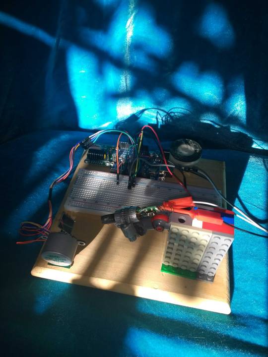
Current state of some projects
So let's see the last couple of days I've been working on refining the household thermostat project that I have. I realized that it's not robust that when the Wi-Fi router goes down that it doesn't reconnect automatically I need to do that. I really don't like the graphics or the webpage that it's serving up right now so I went ahead a couple days ago and made much nicer SVG graphics for the thermostat icons. The next step is figuring out how to include an SVG into an embedded web page inside an embedded microcontroller which shouldn't be too hard I mean SVG is basically just a XML format but still I haven't done seen it working yet.
Otherwise I'm still having this very frustrating problem of it not actually operating as a thermostat.
When it's sitting on my desk and it's attached to a relay that is not attached to the heating system it seems to work just fine but as soon as I attach to the heating system for some reason, even though the manual buttons work it doesn't seem to turn on and off when it senses the temperature is at a point where it needs to be switched. It is my hope that we compiling the code, going through cleaning up as much stuff as I can etcetera etcetera etcetera is going to help me if not figure out where the problem is, at least maybe just magically fix it- because it does seem to be magically broken as well. so I cleaned it up I'm going to try and upload it probably sometime today.
The other thing that I'm working on right now is the laser harp and one of my big problems is that even though I've got a crap ton of transistors and I've got one that is a near replacement for the 2N2222 resistor that I needed it's still not quite right so I'm getting something out of the laser but I'm not sure what's going on with its dimness. I need to rewrite the code for a bit more of diagnostic testing on each of these individual components before I actually try running it as a laser harp to see what is functioning and what is not because right now. I can get sound out of it, I can send midi signals, but getting the servo to rotate the way that I want it to and getting the laser fire that I want it to are two real big nopes at this point.
So yeah I guess the next step is writing test code for the laser firing which is pretty simple that'll just be a basically a blank sketch and then digging through and figuring out how to make this particular Servo in server controller work.
On another note I think I may have added two components to the fried component graveyard yesterday. one of the servo controllers was very very hot when I was feeding at 12 volts I think it was expecting 5 but it might still be alive we'll see. One of those replacement transistors I'm not clear I think I got my collector in my emitter reversed one point which I don't think is deadly but we'll find out. Fortunately if I did fry both of the components I'm out a whole dollar and .26 cents.
1 note
·
View note
Text
Preview: A.IR Shield ESP8266/ESP32 Tx, a high-end IR Shield
Preview: A.IR Shield ESP8266/ESP32 Tx, a high-end IR Shield
A.IR Shield ESP8266/ESP32 Tx for AnalysIR with IRBlasters
The latest member of our MakeIR series of devices & kits is the A.IR Shield ESP8266/ESP32 Tx. This shield works out of the box with AnalysIR and is essentially plug & play, with additional custom Firmware options. This shield is a ‘sibling’ to our related TRx shield, and features IR multi-send only vs the send & receive of the TRx shield.…
View On WordPress
#Air Conditioner#Alexa#AnalysIR#Arduino#ESP32#ESP8266#Infrared#IR#IR signals#IRLib#IRremote#MakeIR#NodeMCU#Remote control#Wemos D1 Mini#Wemos ESP32#WiFi
1 note
·
View note
Video
youtube
IoT Web based Smart Shopping🛒Trolley with ESP32-CAM QR Code Mobile📱Cart Application | iot based smart shopping cart using rfid and nodemcu | smart trolley using barcode scanner | smart car parking system using arduino literature review | rfid based car parking system using arduino and vb.net | smart shopping cart | Trolley for malls near me | Foldable Trolley for Shopping | Grocery Trolley with Wheels | Supermarket Trolley manufacturers | Shopping Trolley Bag | Mall Trolley price | IOT BASED SMART SHOPPING TROLLEY | IOT Based Smart Shopping Trolley for Mall.***********************************************************If You Want To Purchase the Full Working Project KITMail Us: [email protected] Name Along With You-Tube Video LinkWe are Located at Telangana, Hyderabad, Boduppal. Project Changes also Made according to Student Requirementshttp://svsembedded.com/ https://www.svskits.in/ http://svsembedded.in/ http://www.svskit.com/M1: 91 9491535690 M2: 91 7842358459 We Will Send Working Model Project KIT through DTDC / DHL / Blue Dart / First Flight Courier ServiceWe Will Provide Project Soft Data through Google Drive1. Project Abstract / Synopsis 2. Project Related Datasheets of Each Component3. Project Sample Report / Documentation4. Project Kit Circuit / Schematic Diagram 5. Project Kit Working Software Code6. Project Related Software Compilers7. Project Related Sample PPT’s8. Project Kit Photos9. Project Kit Working Video linksLatest Projects with Year Wise YouTube video Links157 Projects https://svsembedded.com/ieee_2022.php135 Projects https://svsembedded.com/ieee_2021.php 151 Projects https://svsembedded.com/ieee_2020.php103 Projects https://svsembedded.com/ieee_2019.php61 Projects https://svsembedded.com/ieee_2018.php171 Projects https://svsembedded.com/ieee_2017.php170 Projects https://svsembedded.com/ieee_2016.php67 Projects https://svsembedded.com/ieee_2015.php55 Projects https://svsembedded.com/ieee_2014.php43 Projects https://svsembedded.com/ieee_2013.php1100 Projects https://www.svskit.com/2022/02/900-pr...***********************************************************1. Smart Shopping Trolley with Automated Billing using Arduino2. RFID Based Smart Shopping Cart Using Arduino | RC5223. Automated Smart Trolley with Smart Billing Arduino | RFID4. IoT based Smart Shopping Cart using RFID and NodeMCU5. RFID based Shopping trolley6. IoT based Smart Door Lock System using NodeMCU7. IOT Based Smart Attendance System Project using NodeMCU ESP82668. DIY Smart Wi-Fi Video Doorbell using ESP32 and Camera9. IoT based Fire Alarm System Project using NodeMCU ESP826610. The Internet of Things with ESP32 | webserver | IoT Design Pro11. IoT based Smart Irrigation System using Soil Moisture Sensor12. Moduino X Series - Industrial IoT module based on ESP3213. Iot Home Automation Using ESP-32 with videos (Hindi
0 notes
Video
youtube
PCF8574 GPIO Extender - With Arduino and NodeMCU
In my last tutorial, I talked about the TCA9548A MUX which can be used to add at the max of 64 I2C or I²C sensors to your Arduino/ESP8266/ESP32.In this tutorial, I am going to talk about the PCF8574 8-bit GPIO Port Extender. It is one of the many GPIO extenders available in the market.This tiny little board becomes a life saver When you run out of pins on your Arduino. This "GPIO (General Purpose Input Output) pin extender" provides an additional 8 pins (P0 ~ P7) which can be used to 'output a signal' or 'read a signal as an input'.These modules run on the I2C bus, and if daisy-chained you can connect upto 8 of these devices in a project. Each device will give us an additional 8-bits of GPIO enabling 64 GPIOs in total.These ICs are ridiculously cheap and can be bought easily from eBay or AliExpress. If you don't want to worry about the wiring and just want to keep your project really "simple", then you can buy these fully assembled breakout boards. You just need to hook them up to the I2C bus and you are all ready to go.
Blog Post: https://diyfactory007.blogspot.com/2018/12/pcf8574-gpio-extender-with-arduino-and.html
1 note
·
View note
Photo

🇧🇷 Placas customizadas (DIY) tipo faça você mesmo, a melhor forma de aprender e ensinar. Hardware, Software e Firmware ---------------------------------- 🇺🇸 Custom Boards (DIY) type do it yourself, the best way to learn and teach. Hardware, Software and Firmware ---------------------------------- #board #Standalone #customizacao #desenvolvimento #engineering #arduino #arduinouno #arduinonano #esp8266 #esp #nodemcu #hardware #software #iot #walproj #projetosmaker #projetoseletronicos #esp32 #mbz https://www.instagram.com/p/B3V6peBjSmb/?igshid=hqoexy11ucgy
#board#standalone#customizacao#desenvolvimento#engineering#arduino#arduinouno#arduinonano#esp8266#esp#nodemcu#hardware#software#iot#walproj#projetosmaker#projetoseletronicos#esp32#mbz
1 note
·
View note
Text
Arduino Tutorial 61: NodeMCU ESP8266 mit OLED Display

In diesem Tutorial möchte ich einen Mikrocontroller mit einem verbauten OLED Display vorstellen. Der Mikrocontroller ist ein NodeMCU mit einem ESP8266 Wi-Fi Chip.

NodeMCU mit OLED Display Einen NodeMCU habe ich bereits im Tutorial NodeMCU – “Einer für (fast) Alles!” vorgestellt und möchte hier nun auf den betrieb mit dem OLED Display eingehen. Der Microcontroller wurde mir vom Onlineshop Makershop.de für ein Review zur Verfügung gestellt.
Bezug
Den Mikrocontroller kannst du auf ebay.de im Shop von Makershop.de für 14,45 € erwerben (Versandkosten fallen nicht an).
Technische Daten des NodeMCU mit OLED Display
NodeMCU - 12 digitale Pins - 1 analoger Eingang - Micro-USB Buchse - Eingangsspannung 4,75V bis 12V - Abmaße 6,2 cm x 2,7 cm OLED Display - Abmaße 0,96 Zoll (2,7 cm x 1,5 cm)
Besonderheiten
Der NodeMCU mit OLED Display ist breiter als der NodeMCU.

Vergleich von einfachen NodeMCU mit einem mit Display Wenn der Mikrocontroller auf ein Steckbrett verbaut wird, so kann man nur eine Pinreihe verwenden.

NodeMCU auf einem Steckbrett verbaut Auf dem NodeMCU mit OLED Display ist bereits ein Sketch installiert, welcher auf dem Display einige Funktionen zeigt.
Quellcode
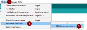
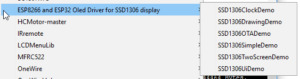
In den nachfolgenden Beispielen möchte ich aufzeigen wie das Display des Mikrocontrollers betrieben wird. Installation der benötigten Bibliothek Für den Betrieb des Displays wird eine Bibliothek benötigt, diese kann man bequem über die Arduino IDE installieren. Dazu wird über das Hauptmenü der Eintrag "Sketch" (1) -> "Bibliothek einbinden" (2) -> "Bibliotheken verwalten ..." (3) navigiert.
Öffnen des Boardverwalters Es sollte sich nun nach einer kurzen Ladezeit der Boardverwalter öffnen. In diesem Dialog suchen wir zunächst nach dem Eintrag "SSD1306" (1) danach wird der Eintrag "ESP8266 and ESP32 Oled Driver for SSD1306 ...."(2) ausgewählt. Nun noch die Schaltfläche "Installieren" (3) betätigen. Nachdem die Installation erfolgreich war, kann der Dialog mit der Schaltfläche "Schließen" (4) geschlossen werden.
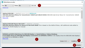
Boardverwalter, installieren der SSD1306 Bibliothek für das OLED Display Wie üblich bringt auch diese Bibliothek einige Beispiele mit, welche nach einer kleinen Konfiguration lauffähig sind.
ESP OLED Display Bibliothek - Beispiele SDA & SCL Das Display ist über die digitalen Pins D1 - SDA & D2 - SCL angeschlossen, dieses muss in den Beispielen geändert / angepasst werden. Dann sind diese jedoch lauffähig. Hello World! Als Erstes ein Klassiker "Hello World!". Für die Darstellung von Text kann man zwischen 3 Schriftgrößen wählen.

Schriftgrössen auf dem OLED Display Für unser "Hello World!" reicht die Schriftgröße 16 völlig aus. #include //Bibliothek für die Arduino IDE setTextAlignment(TEXT_ALIGN_LEFT); display->setFont(ArialMT_Plain_16); display->drawString(0, 0, "Hello World!"); } //Array mit den Frames für das Display. //Jeder Eintrag in diesem Array repräsentiert eine Darstellung //des Displays. FrameCallback frames = { helloFrame}; //Anzahl der maximalen Frames welche angezeigt werden sollen. const int frameCount = 1; void setup() { //Setzen der Bildwiederholungsfrequenz ui.setTargetFPS(60); //Setzen der Frames sowie die Anzahl der Frames. ui.setFrames(frames, frameCount); //Initialisieren der Oberfläche. ui.init(); //Bildschirm drehen, ansonsten ist die Darstellung auf dem Kopf. display.flipScreenVertically(); } void loop() { int remainingTimeBudget = ui.update(); } Textausgabe auf dem OLED Display

Ausgabe des Textes "Hello World!" auf dem OLED Display Einfache Grafiken Auf dem OLED Display können einfache Grafiken angezeigt werden. In dem Sketch, welcher ab Werk auf dem NodeMCU installiert wurde ist das Wifi Zeichen zu sehen. Wollen wir uns also nun mal ansehen wie eine Grafik auf dem Display erzeugt werden kann. X BitMap Image Die Bilder, welche auf dem Display angezeigt werden können, müssen im X Bitmap Format vorliegen. Auf Wikipedia ist ein kleiner Beitrag zum X Bitmap Format zu finden: X BitMap (XBM) ist ein Format für die Darstellung von monochromen Rastergrafiken, hauptsächlich Cursors und Icons. Das XBM-Dateiformat wurde 1989 durch XPM für X11 ersetzt. Die Grafiken bestehen aus reinen Textdateien; sie können mit einem einfachen Texteditor bearbeitet und direkt in C-Quellcode eingebunden werden. Seite „X BitMap“. In: Wikipedia, Die freie Enzyklopädie. Bearbeitungsstand: 21. November 2017, 09:08 UTC. URL: https://de.wikipedia.org/w/index.php?title=X_BitMap&oldid=171218654 (Abgerufen: 17. August 2018, 10:06 UTC) Umandeln von PNG nach XBM Um ein Bild in das XBM Format umzuwandeln, muss man nicht unbedingt spezielle Software erwerben, man kann dieses bequem online mit dem Tool https://www.online-utility.org/image/convert/to/XBM erledigt. Hier lädt man das gewünschte Bild hoch und kann die XBM Datei herunterladen.
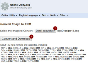
Online PNG to XBM Converter Ich habe mein Logo im Format 48x48 Pixel hochgeladen und eine Datei mit folgendem Inhalt heruntergeladen: #define 1534500608686_width 48 #define 1534500608686_height 48 static char 1534500608686_bits = { 0xFF, 0xFF, 0xFF, 0xFF, 0xFF, 0xFF, 0xFF, 0xF7, 0xBE, 0xEF, 0xFB, 0xFE, 0x07, 0x00, 0x00, 0x00, 0x00, 0xE0, 0x07, 0x00, 0x00, 0x00, 0x00, 0xC0, 0x03, 0x03, 0x00, 0x00, 0x00, 0xC0, 0xA3, 0x3B, 0x8D, 0xA3, 0x69, 0x8E, 0x21, 0x19, 0xCE, 0xB6, 0x6D, 0xC3, 0x73, 0x8B, 0xD9, 0x90, 0x1D, 0xC2, 0x63, 0x1B, 0xCB, 0xB5, 0x1D, 0xC2, 0x03, 0x00, 0x20, 0x80, 0x01, 0xC0, 0x03, 0x00, 0x78, 0xF4, 0x01, 0xC0, 0x03, 0x00, 0x3C, 0x01, 0x02, 0x80, 0x01, 0x00, 0x9E, 0xC2, 0x01, 0xC0, 0x03, 0x00, 0x67, 0xF5, 0x01, 0xC0, 0x03, 0x80, 0x97, 0xFE, 0x03, 0x40, 0x03, 0xC0, 0x6D, 0x7D, 0x06, 0xC0, 0x03, 0xF0, 0xD6, 0xFD, 0x0E, 0xC0, 0x03, 0xF0, 0x5F, 0xBE, 0x39, 0xC0, 0x01, 0xFC, 0x7F, 0xFF, 0x36, 0xC0, 0x03, 0xEC, 0xBF, 0x5F, 0x63, 0xC0, 0x03, 0xFE, 0xDF, 0x7F, 0xDB, 0xC0, 0x03, 0xFF, 0xFF, 0xEF, 0xBD, 0x81, 0x03, 0xFF, 0xEF, 0xDF, 0x9B, 0xC1, 0x83, 0xFF, 0x7F, 0xF7, 0xFF, 0xC3, 0x01, 0xFF, 0xEF, 0xFF, 0xFF, 0xC3, 0x03, 0xFF, 0xFF, 0xFF, 0xFF, 0xC1, 0x03, 0xFF, 0x77, 0xFF, 0xFF, 0xC1, 0x03, 0xFE, 0xF7, 0xFF, 0xFF, 0x80, 0x03, 0xF8, 0xFF, 0xFF, 0x7F, 0xC0, 0x03, 0xF8, 0xFF, 0xFF, 0x3F, 0xC0, 0x01, 0xF0, 0xFE, 0xFF, 0x1F, 0xC0, 0x03, 0xF0, 0xFE, 0xFF, 0x0F, 0xC0, 0x03, 0x00, 0xFF, 0xFF, 0x0F, 0xC0, 0x03, 0x80, 0xFB, 0xFF, 0x03, 0xC0, 0x03, 0xC0, 0xFD, 0xFF, 0x01, 0x40, 0x03, 0xC0, 0xFD, 0xFF, 0x00, 0xC0, 0x01, 0x40, 0xF8, 0x77, 0x00, 0xC0, 0x63, 0x00, 0xFC, 0x2F, 0x00, 0xC0, 0x43, 0x06, 0x1C, 0x0D, 0x00, 0x40, 0x63, 0x06, 0xDC, 0xCD, 0x6E, 0xC6, 0x63, 0xC6, 0xCD, 0x4C, 0x6C, 0xC6, 0x63, 0x06, 0xCC, 0xEC, 0x6E, 0xCE, 0x21, 0x04, 0x24, 0x88, 0xC2, 0x4E, 0x03, 0x00, 0x00, 0x00, 0x00, 0xC6, 0x03, 0x00, 0x00, 0x00, 0x00, 0xC0, 0x07, 0x00, 0x00, 0x00, 0x00, 0xE0, 0x7F, 0xDF, 0xF7, 0xFD, 0xFD, 0xFF, 0xFF, 0xFF, 0xFF, 0xFF, 0xBF, 0xFF, }; Quellcode Ich musste den Datentyp für das Bild von "static char " in "const uint8_t" ändern. Ansonsten habe ich mich am Beispiel orientiert. #include //Bibliothek für die Arduino IDE drawXbm(x + 34, y + 14, img_Width, img_Height, image); } //Array mit den Frames für das Display. //Jeder Eintrag in diesem Array repräsentiert eine Darstellung //des Displays. FrameCallback frames = { imageFrame}; //Anzahl der maximalen Frames welche angezeigt werden sollen. //Wenn der Wert 0 ist dann wird nur das erste Frame angezeigt und //die Seitenanzeige im Display entfällt. const int frameCount = 0; void setup() { //Setzen der Bildwiederholungsfrequenz ui.setTargetFPS(60); //Setzen der Frames sowie die Anzahl der Frames. ui.setFrames(frames, frameCount); //Initialisieren der Oberfläche. ui.init(); //Bildschirm drehen, ansonsten ist die Darstellung auf dem Kopf. display.flipScreenVertically(); } void loop() { int remainingTimeBudget = ui.update(); } Ausgabe des Bildes auf dem OLED Display Das Logo wird relativ gut dargestellt, jedoch wird deutlich das bei einem weniger aufwändigen Bild das Display seine stärken zeigen kann.

Darstellen des Logos auf dem OLED Display Read the full article
1 note
·
View note
Photo
IR sensor - - - - - - - - - ➖➖➖➖➖➖➖➖➖➖➖➖ Follow Us On: @decoders8421 Tag Your Friends 👼. Ask any query or doubt in comments. ➖➖➖➖➖➖➖➖➖➖➖➖ - #electronics #sensor #irsensor #breadboard #extc #circuit #resistor #capacitor #arduino #sensormodule #pirsensor #arduinouno #raspberrypi4 #raspberrypi3 #raspberrypizero #esp32 #nodemcu #ic555 #vlsi #pcbdesign #pcb #electronicsengineering #smd #project #arduinofun https://www.instagram.com/p/CA0FzipnafS/?igshid=f9hslxeg1cq6
#electronics#sensor#irsensor#breadboard#extc#circuit#resistor#capacitor#arduino#sensormodule#pirsensor#arduinouno#raspberrypi4#raspberrypi3#raspberrypizero#esp32#nodemcu#ic555#vlsi#pcbdesign#pcb#electronicsengineering#smd#project#arduinofun
0 notes
Link
do arduino, esp, programming, iot projects, pcb and circuit designing etc Hello Dear, I am Electro/Mechanical Engineer with more than 4 Years of Experience in dealing with Arduino and Related Projects. Ensure you for High Quality Work. Just Tell me Your Requirements... My Services Include: Arduino Coding (with explanation, if required)Circuit Design/DiagramPCB DesigningComponents RequiredSimulations on TinkerCad or ProteusESP32, ESP8266-NodeMCUSensors InterfacingVideo DemonstrationIoT ProjectsAndroid iOS AppHome AutomationIndustrial Automation (based upon Arduino/Microcontroller) and Any other Consultation According to Your Need... I believe on [ Quality Delivery on Time Free Help/Consultation Optimum Customer Satisfaction ]FAQI want to do Arduino Programming, could you help me?Please Tell me About your Requirements before Placing the Order.I want to implement the IoT based Automation System for my HomePlease Give me Details about Your Requirements before Placing the Order.I need the Sensors Interfacing and Automation System for my ProcessPlease Give me Details about Your Requirements before Placing the Order. do arduino, esp, programming, iot projects, pcb and circuit designing etc
0 notes
Text
Modulo Rele 1 Canal Led Indicador Para Arduino Pi Pic 5v/10a [ Código 01 ]
Modulo Rele 1 Canal Led Indicador Para Arduino Pi Pic 5v/10a [ Código 01 ]
*Comprando antes da 13:30 horas será enviado no mesmo dias após esse horário, só no dia seguinte, de segunda a sexta-feira exceto Sábado, Domingo e Feriado… Rele 5v 1 Canal Modulo Arduino Nodemcu Esp8266 Esp32 Este modulo Relé 5V com 1 canal é a alternativa perfeita pra quem busca um módulo compacto e de qualidade para projetos com Arduino e outros controladores. Com este módulo você consegue…
View On WordPress
0 notes