#perfboard
Explore tagged Tumblr posts
Visit Tumblr Blog
Explore Tumblr blogs with no restrictions, modern design and the best experience.
Last Seen Tumblr Blogs


Fun Fact
Premium Tumblr themes are available from anywhere between $9 to $49.
Text
I made a guitar pedal!!!
it's so epic and cool
it's called the bazzfuss

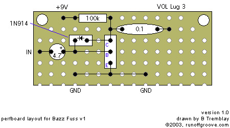


Here's a stoopid little dinky demo I made with my bass
#music#my posts haha#electronic#electronics#soldering#circuit#perfboard#guitar#bass#bass pedals#guitar pedals#pinecil#pine64#pts music
7 notes
·
View notes
Text
Newxie prototype testing success 🦃🥧
We just had a turkey nap and are now back to work. These vertical-mount 1.14" IPS TFT displays have 240 x 135 pixels and are 'stackable' horizontally on a breadboard or perfboard. There are just enough pins to control the TFT and backlight, so if you want to individually control each display, just have them share the SPI and DC pins, then have a unique chip select pin for each. These could make for cute 'flip' display simulations or faux nixie bulbs. The prototypes work fine; we just need to adjust the slot size. The panelized PCBs can be booked, and there is pie.
135 notes
·
View notes
Text


EHX - Big Muff
"this is not the first batch. first batch had "fuzz" instead of "tone" and the power switch was on the volume knob. ... for the first couple months they were all assembled on perf board, and theres assorted variations even within that because they were kinda winging it frankly. ... the first version Big Muffs with the perfboard layout have the tone control sent to ground via the input socket and the rest of the circuit via the output socket. I've only ever seen the conventional triangle Big Muffs with the PCBs having the circuit sent to ground via the output socket because of how it's all laid out inside."
cred: facebook.com/Chris Byrne
56 notes
·
View notes
Text

Goal for vacation is to get a solid perfboard layout so I can start soldering Callisto next week
(goal is also to not chew on the walls trying to figure out Squish's button/led/potentiometer options)
4 notes
·
View notes
Text
In developing any Electrical and Electronics System we must first conceptualize and design the circuit and then go to testing and debugging only after these two stages are complete, we go for final fabrication on the PCB. In all these three processes testing and debugging is the most important because here we ascertain that the circuit we developed is working as intended and there is no bugs in the system which might affect the performance of the device. In this stage we fabricate the circuit on the Breadboard or the Perfboard like this with the help of through hole package components to iron out kinks. It is made up of Fiber Glass which is extremely durable and flexible which makes it great to be used in final industry ready product. It has tin coating on holes at one side which allows you to design the PCB on single side only without having to worry about component placement on the board. It is extremely easy to work with and you can easily solder on this board as it has soldering spots and some gap between them to avoid short circuiting but still you need to take care while designing the circuit of these things.
3 notes
·
View notes
Text
prototyping circuit boards
Prototyping circuit boards allows engineers and hobbyists to test and refine electronic designs before full-scale production. These boards often feature pre-drilled holes or customizable layouts, enabling easy placement and connection of components. Prototyping helps identify flaws, optimize performance, and reduce manufacturing costs. Popular types include breadboards and perfboards, offering flexibility during development. It’s a crucial step in creating functional, reliable, and efficient electronic devices.
prototyping circuit boards
0 notes
Text
Well if the fun is in the project sure, but I've adopted a "just buy the module" approach for my projects.
Instead of putting everything on a custom PCB I can just buy breakout boards for everything and then put it onto perfboard later.
report from the tiktok mines:
i found a strange livestream of an egg attached to a stick, rotating in place above a bowl of yolks. on the left and right was a needle and a small metal ball on a stick. specific amounts of donations would trigger the needle or "hammer" to strike the egg automatically. serene piano music, and distant birds chirping play in the background.
periodically, as the egg would break, a hand would come on screen to replace it.
right as i went for the screen recording it ended.
i find this new phenomenon of hyper specific livestream busking fascinating. a strange reward for a small fee. imagining an analogue equivalent of these sorts of streams makes me think of an eccentric vending machine museum. put a coin in and contribute to the egg being slowly pulverized.
this concludes the tiktok report.
10K notes
·
View notes
Text
Woo, got some zero ohm resistors and nice perfboards in. Stripboard is great and very adaptable, but the convenience of perf boards already laid out with trace patterns is nice. Sometimes you don't want to spend a couple hours figuring out which strips you gotta cut and where, you want to pop parts in like a protoboard.
I got a few pieces of 2-3-5 pattern, which you can still cut the large traces for that flexibility but the point is minimal layout.
#nicoisms#only complaint I have is the busses on the 2-3-5 perf have no holes so I'll have to do that myself to use them
0 notes
Text
It's somewhat frustrating being a Eurorack enthusiast without the funds to purchase all the $200-$600 modules I want, or indeed usually the $80 ones.
I mean, I get why prices are high. Music tech and hardware synthesis are high-priced, boutique markets to begin with, and Eurorack is a boutique's boutique, where even some of the biggest manufacturers are little more than a garage operation, and several of the well-known and celebrated brands have a single employee.
It's also a little annoying that, in the time between when I started planning to have a Eurorack system one day and now, I've watched more than one manufacturer pop up with amazing modules that I really want — and then liquidate their stock and shut down the business a few years later. Mutable Instruments is only the most obvious example. (Man, would I like a Plaits.)
But anyway, my complaint isn't with the pricing per se, it's with my impoverished budget, which doesn't reach the levels of buying modules, or even full kits, most of the time. Nor can I afford any of the controllers or accessories that everyone else seems to have, the Beat Steps and the ∅-Controls and the DC-coupled audio interfaces.
I mean, I make do, scraping up funds and building things out of perfboard and salvaged components and scraps of sheet aluminum, and still I have a legitimate Eurorack system that's a reasonable monosynth and am planning future expansions. So I keep going.
But if anybody has an MI Plaits kicking around, going unused and unloved, I'd take one, y'know?
0 notes
Text
Fabriquer un splitter mixer audio
Dans cet article je vous montre comment fabriquer un splitter-mixer pour l'audio.

View On WordPress
#alimentation simple#amplificateur opérationnel#Blender#buffer#Mixer#Pédale ABY#Perfboard#Schematic#Splitter#tone sucking
0 notes
Note
Temperature control is pretty much non-negotiable if you want to have a good time working with anything on a board IMO, I have done plenty of emergency repairs with a wall-power hardware store iron and it's terrible. Ideally you want to have a digital readout so that you can set it reliably every time but an analog control will at least mean you can dial it in to what you like and leave it there.
Soldering homemade projects on perfboard/stripboard is hard mode for through hole because you have no solder mask and solder without a mask loves to form annoying bridges you have to go and clean up. If this is troubling you try and find a project on PCB and marvel at how easy a full PCB with solder mask makes basically any kind of soldering.
Also hard agree on Just Skip Lead, I came around on lead-free-only in the past few years and it's really not that bad. The only time I would turn to lead is working with vintage electronics where it's sometimes handy to mix fresh leaded solder into old joints before desoldering them to soften them up and improve flow, but that's a niche application.
how did you learn how to solder? is it something someone can teach themself?
my dad taught me when i was 7 so unfortunately i have damn near zero useful advice for you :( PROBABLY you can teach yourself from, like, youtube...? its not that hard though; 7 year old me was a dipshit so if they can do it you can too
uhh, it'll go easier if you have a halfway decent temperature controlled soldering iron (i use a Weller and it cost $120 iirc) and use leaded solder + flux. i also like to use small conical tips rather than the chisel tips my soldering iron came with, but thats really down to personal preference. touch the iron to the pins + pads and melt solder onto the pad, not the iron directly. if you used to much solder you can use solder wick dipped in flux to schlorp it off. masking tape helps a lot for fixturing things while you solder. my favorite trick for header pins is to stick the part + pins in a solderless breadboard while you work, but if thats not an option, tack solder just the ends of the header so you can reheat + wiggle it around as needed easily. use shrink tubing + hot air pencil to conceal your sins when soldering wires together. i think thats all the soldering tips i have
67 notes
·
View notes
Text
Cute and clickie square switches
square switches, swear scritches! we got these samples of "12mm" square tactiles with an embedded white LED - they come from the same factory as our '808 step switches' (https://www.adafruit.com/search?q=808+step) and look like they can go in every day 12mm tactile footprints with an additional LED in each corner. they have a nice fairly even glow and can fit into a breadboard or perfboard! now that these are ladyada-approved, we'll get them on order soon.
16 notes
·
View notes
Text


Harris-Fandel Co. - The Liverpool Fuzz
"In November of 1968 a new fuzz box was introduced to the world through the pages of Billboard magazine. The pop publication ran a little blurb proclaiming a new fuzz-tone that "shatters sound" and can "last more than 1,000 hours without a battery change". Known as the Liverpool Fuzz Tone, from Ridinger Associates, it was a fairly unique circuit for the time that utilized 3 germanium transistors and ran off of 9v. Primitive and raw, it was a hidden gem of American 60's fuzz. One month later the Liverpool Fuzz was given a similar treatment in the UK publication Beat Instrumental. Although lacking in classic American hyperbole, this small write-up served as the European introduction to one of the most prolific builders of the 1970s. And finally, a few months later we would get to actually see the Liverpool Fuzz highlighted in a photo ad, seemingly associated with New England distributor Harris-Fandel, showing a small table-top unit with a hardwired output cable and an on/off switch. And while the late 60s were flooded with unoriginal copies and clones, the Liverpool Fuzz Tone immediately stood out, and still holds a very significance place in the history of guitar effects…
So what's the deal with this thing and why is it so important?
Well for those unaware, this is the first effect built and released by Ridinger Associates, or better known as Steve Ridinger of Danelectro fame, Arion Effects, and most importantly fOXX! The story is that he originally built the first Liverpool Fuzzes in 1966 when he was just 14 yrs old. The lore goes on to say that as a young teenager he didn't have the money to buy a fuzz pedal, nor did he have access to any fuzz schematics, so he came up with a fuzz/drive circuit of his own. These early units were all hand-wired using perfboard. Around 1968 he did a deal with a US distributor and also outsourced the manufacturing to a third party who paired it down to a small black enclosure and incorporated a printed circuit board for a cheaper/faster build. Ridinger estimates between 500-1,000 were produced in this time (1966-1969). And while that seems like a large number compared to some other pedals we have discussed, the nondescript nature of the blank black enclosure combined with no labeling of any kind, has made it near impossible to track one of these down. And at this point I have only seen 2 in my 20+ years of collecting. Following the Liverpool Fuzz, Ridinger created and released the Fox Wa Pedal, which would be the first time he would use the "Fox" name, and ultimately lead to him starting the fOXX brand just a year later. In the world of vintage guitar pedal collectors these two effects mean a lot. Without Steve Ridinger deciding to dip his toes into building, marketing and distributing stompboxes at such an early age, we may never have heard of fOXX or the best fuzz of all-time, the Tone Machine! And it all started in 1966 with a little hand-built effect called the Liverpool Fuzz Tone."
cred: tonemachinesblog.com; facebook.com/Ed Skymall; facebook.com/Chris Martin
16 notes
·
View notes
Photo

Double sided perf board 🙌🙌🙌 #diy #tech #electronics #hardware #perfboard #circuit #make #makersmovement #makersgonnamake #nerdlife
1 note
·
View note
Photo

Finished the #3dprinted enclosure for my #resetternet #project. Such a beautiful piece designed with #openscad. This project was featured on #hackaday and now is complete of his box. I've not designed the pcb since is very simple, so I've used a standard #perfboard. See my blog, www.settorezero.com, for entire project and #sourcecode, soon I'll upload the STL files for the box. . . . . . . #smarthome #iot #automation #homeautomation #electronics #engineering #manufacturing #startup #tinkering #3dprinting #github #blogger #techblogger #youtuber #picoftheday #maker #nodemcu #arduino #developer #coder #programmer https://www.instagram.com/p/BtDW_UfnAsU/?utm_source=ig_tumblr_share&igshid=mz0ysfb8myrk
#3dprinted#resetternet#project#openscad#hackaday#perfboard#sourcecode#smarthome#iot#automation#homeautomation#electronics#engineering#manufacturing#startup#tinkering#3dprinting#github#blogger#techblogger#youtuber#picoftheday#maker#nodemcu#arduino#developer#coder#programmer
0 notes
Link
We're going to see how we can build an affordable Arduino LED Strip controller for less than 10$!
Timeline: Intro 0:00 Control Brightness (Theory) 0:29 Control Color (Theory) 1:38 Circuit 2:34 Breadboard Assembly 5:11 Perfboard Assembly 6:26 LED Strip Installation 6:43 Coding 7:14
You will need: - An Arduino Nano - 3x Logic Transistors (IRL540) - 3x Heat Sinks - 3x Large Resistors (larger than 100KΩ) - A perforated board (perfboard)
Download all the needed FILES Here! Official Arduino IDE software: https://www.arduino.cc/en/software/ Arduino Sketches: https://github.com/TheWorkshopByGM/Arduino_LED_Strip_Controller Circuit Schematic: https://github.com/TheWorkshopByGM/Arduino_LED_Strip_Controller
If you still need some help with your Arduino LED Strip controller let me know in the Comment section below!
Subscribe so you don't miss any future episode: https://www.youtube.com/channel/UCptp9GmxNwcvE0jj4-lLFeg?sub_confirmation=1
Like the video to show me your Support!
And share this video with your friends: https://youtu.be/CbfimKN3_vc
Recommended Playlist – https://www.youtube.com/playlist?list=PL60kG7wM9f_x73ZeWR9d-yR8wY8VxzWeL
Let’s Connect: TickTock – https://www.tiktok.com/@theworkshopbygm Instagram – https://www.instagram.com/theworkshop.by.gm/ Facebook – https://www.facebook.com/TheWorkshopByGM/ GitHub – https://github.com/TheWorkshopByGM Instructables – https://www.instructables.com/member/theworkshop.by.gm/ Pinterest – https://www.pinterest.com/theworkshopbygm/
#arduino#arduino project#smart room#smart home#home automation#smart home technology#iot#internet of things#raspberry pi#diy#do it yourself#maker#engineer#engineering#electronics#electrical#electrical engineering#computer science#computer engineer#computer engineering#programming#led#led light#rgb lights#rgb setup#rgb led#led setup#smart lighting#smart led#light emitting diode
3 notes
·
View notes