#single side pcb
Explore tagged Tumblr posts
Visit Tumblr Blog
Explore Tumblr blogs with no restrictions, modern design and the best experience.
Last Seen Tumblr Blogs


Fun Fact
Tumblr Inc. is funded by 13 investors.
Text
How a Computer Works - Part 1 (Components)
I am about to teach you on a real fundamental, connecting up electronic components level, how a computer actually works. Before I get into the meat of this though (you can just skip down below the fold if you don't care), here's the reasons I'm sitting doing so in this format:
Like a decade or two ago, companies Facebook pushed this whole "pivot to video" idea on the whole internet with some completely faked data, convincing everyone that everything had to be a video, and we need to start pushing back against that. Especially for stuff like complex explanations of things or instructions, it's much more efficient to just explain things clearly in text, maybe with some visual aids, so people can easily search, scan, and skip around between sections. It's also a hell of a lot easier to host things long term, and you can even print out a text based explainer and not need a computer to read it, keep it on a desk, highlight it, etc.
People are so clueless about how computers actually work that they start really thinking like it's all magical. Even programmers. Aside from how proper knowledge lets you get more out of them, this leads to people spouting off total nonsense about "teaching sand to think" or "everything is just 1s and 0s" or "this 'AI' a con artist who was trying to sell me NFTs a month ago probably really is an amazing creative thinking machine that can do everything he says!"
We used to have this cultural value going where it was expected that if you owned something and used it day to day, you'd have enough basic knowledge of how it worked that if it stopped working you could open it up, see what was wrong, and maybe fix it on your own, or maybe even put one together again from scratch, and that's obviously worth bringing back.
I'm personally working on a totally bonkers DIY project and I'd like to hype up like-minded people for when it gets farther along.
So all that said, have a standard reminder that I am completely reliant on Patreon donations to survive, keep updating this blog, and ideally start getting some PCBs and chips and a nice oscilloscope to get that mystery project off the ground.
Electricity probably doesn't work like how you were taught (and my explanation shouldn't be trusted too far either).
I remember, growing up, hearing all sorts of things about electricity having this sort of magical ability to always find the shortest possible path to where it needs to get, flowing like water, and a bunch of other things that are kind of useful for explaining how a Faraday cage or a lightning rod works, and not conflicting with how simple electronics will have a battery and then a single line of wire going through like a switch and a light bulb or whatever back to the other end of the battery.
If you had this idea drilled into your head hard enough, you might end up thinking that if we have a wire hooked to the negative end of a battery stretching off to the east, and another wire stretching off to the east from the positive end, and we bridge between the two in several places with an LED or something soldered to both ends, only the westernmost one is going to light up, because hey, the shortest path is the one that turns off as quickly as possible to connect to the other side, right? Well turns out no, all three are going to light up, because that "shortest path" thing is a total misunderstanding.
Here's how it actually works, roughly. If you took basic high school chemistry, you learned about how the periodic table is set up, right? A given atom, normally, has whatever number of protons in the core, and the same number of electrons, whipping all over around it, being attracted to those protons but repelled by each other, and there's particular counts of electrons which are super chill with that arrangement so we put those elements in the same column as each other, and then as you count up from those, you get the elements between those either have some electrons that don't fit all tight packed in the tight orbit and just kinda hang out all wide and lonely and "want to" buddy up with another atom that has more room, up to the half full column that can kinda go either way, then as we approach the next happy number they "want to" have a little more company to get right to that cozy tight packed number, and when you have "extra" electrons and "missing" electrons other atoms kinda cozy up and share so they hit those good noble gas counts.
I'm sure real experts want to scream at me for both that and this, but this is basically how electricity works. You have a big pile of something at the "positive" end that's "missing electrons" (for the above reason or maybe actually ionized so they really aren't there), and a "negative" end that's got spares. Then you make wires out of stuff from those middle of the road elements that have awkward electron counts and don't mind buddying up (and also high melting points and some other handy qualities) and you hook those in there. And the electron clouds on all the atoms in the wire get kinda pulled towards the positive side because there's more room over there, but if they full on leave their nucleus needs more electron pals, so yeah neighbors get pulled over, and the whole wire connected to the positive bit ends up with a positive charge to it, and the whole wire on the negative bit is negatively charged, and so yeah, anywhere you bridge the gap between the two, the electrons are pretty stoked about balancing out these two big awkward compromises and they'll start conga lining over to balance things out, and while they're at it they'll light up lights or shake speakers or spin motors or activate electromagnets or whatever other rad things you've worked out how to make happen with a live electric current.
Insulators, Resistors, Waves, and Capacitors
Oh and we typically surround these wires made of things that are super happy about sharing electrons around with materials that are very much "I'm good, thanks," but this isn't an all or nothing system and there's stuff you can connect between the positive and negative ends of things that still pass the current along, but only so much so fast. We use those to make resistors, and those are handy because sometimes you don't want to put all the juice you have through something because it would damage it, and having a resistor anywhere along a path you're putting current through puts a cap on that flow, and also sometimes you might want a wire connected to positive or negative with a really strong resistor so it'll have SOME sort of default charge, but if we get a free(r) flowing connection attached to that wire somewhere else that opens sometimes, screw that little trickle going one way, we're leaning everyone the other way for now.
The other thing with electricity is is that the flow here isn't a basic yes/no thing. How enthusiastically those electrons are getting pulled depends on the difference in charge at the positive and negative ends, and also if you're running super long wires then even if they conduct real good, having all that space to spread along is going to kinda slow things to a trickle, AND the whole thing is kinda going to have some inherent bounciness to it both because we're dealing with electrons whipping and spinning all over and because, since it's a property that's actually useful for a lot of things we do with electricity, the power coming out of the wall has this intentional wobbly nature because we've actually got this ridiculous spinny thing going on that's constantly flip flopping which prong of the socket is positive and which is negative and point is we get these sine waves of strength by default, and they kinda flop over if we're going really far.
Of course there's also a lot of times when you really want to not have your current flow flickering on and off all the time, but hey fortunately one of the first neat little electronic components we ever worked out are capacitors... and look, I'm going to be straight with you. I don't really get capacitors, but the basic idea is you've got two wires that go to big wide plates, and between those you have something that doesn't conduct the electricity normally, but they're so close the electromagnetic fields are like vibing, and then if you disconnect them from the flow they were almost conducting and/or they get charged to their limit, they just can't deal with being so charged up and they'll bridge their own gap and let it out. So basically you give them electricity to hold onto for a bit then pass along, and various sizes of them are super handy if you want to have a delay between throwing a switch and having things start doing their thing, or keeping stuff going after you break a connection, or you make a little branching path where one branch connects all regular and the other goes through a capacitor, and the electricity which is coming in in little pulses effectively comes out as a relatively steady stream because every time it'd cut out the capacity lets its charge go.
We don't just have switches, we have potentiometers.
OK, so... all of the above is just sort of about having a current and maybe worrying about how strong it is, but other than explaining how you can just kinda have main power rails running all over, and just hook stuff across them all willy-nilly rather than being forced to put everything in one big line, but still, all you can do with that is turn the whole thing on and off by breaking the circuit. Incidentally, switches, buttons, keys, and anything else you use to control the behavior of any electronic device really are just physically touching loose wires together or pulling them apart... well wait no, not all, this is a good bit to know.
None of this is actually pass/fail, really, there's wave amplitudes and how big a difference we have between the all. So when you have like, a volume knob, that's a potentiometer, which is a simple little thing where you've got your wire, it's going through a resistor, and then we have another wire we're scraping back and forth along the resistor, using a knob, usually, and the idea is the current only has to go through X percent of the resistor to get to the wire you're moving, which proportionately reduces the resistance. So you have like a 20 volt current, you've got a resistor that'll drop that down to 5 or so, but then you move this other wire down along and you've got this whole dynamic range and you can fine tune it to 15 or 10 or whatever coming down that wire. And what's nice about this again, what's actually coming down the wire is this wobbily wave of current, it's not really just "on" or "off, and as you add resistance, the wobble stays the same, it's just the peaks and valleys get closer to being just flat. Which is great if you're making, say, a knob to control volume, or brightness, or anything you want variable intensity in really.
Hey hey, it's a relay!
Again, a lot of the earliest stuff people did with electronics was really dependent on that analog wobbly waveform angle. Particularly for reproducing sound, and particularly the signals of a telegraph. Those had to travel down wires for absurd distances, and as previously stated, when you do that the signal is going to eventually decay to nothing. But then someone came up with this really basic idea where every so often along those super long wires, you set something up that takes the old signal and uses it to start a new one. They called them relays, because you know, it's like a relay race.
If you know how an electromagnet works (something about the field generated when you coil a bunch of copper wire around an iron core and run an electric current through it), a relay is super simple. You've got an electromagnet in the first circuit you're running, presumably right by where it's going to hit the big charged endpoint, and that magnetically pulls a tab of metal that's acting as a switch on a new circuit. As long as you've got enough juice left to activate the magnet, you slam that switch and voom you've got all the voltage you can generate on the new line.
Relays don't get used too much in other stuff, being unpopular at the time for not being all analog and wobbily (slamming that switch back and forth IS going to be a very binary on or off sorta thing), and they make this loud clacking noise that's actually just super cool to hear in devices that do use them (pinball machines are one of the main surviving use cases I believe) but could be annoying in some cases. What's also neat is that they're a logical AND gate. That is, if you have current flowing into the magnet, AND you have current flowing into the new wire up to the switch, you have it flowing out through the far side of the switch, but if either of those isn't true, nothing happens. Logic gates, to get ahead of myself a bit, are kinda the whole thing with computers, but we still need the rest of them. So for these purposes, relays re only neat if it's the most power and space efficient AND gate you have access to.
Oh and come to think of it, there's no reason we need to have that magnet closing the circuit when it's doing its thing. We could have it closed by default and yank it open by the magnet. Hey, now we're inverting whatever we're getting on the first wire! Neat!
Relay computers clack too loud! Gimme vacuum tubes!
So... let's take a look at the other main thing people used electricity for before coming up with the whole computer thing, our old friend the light bulb! Now I already touched a bit on the whole wacky alternating current thing, and I think this is actually one of the cases that eventually lead to it being adopted so widely, but the earliest light bulbs tended to just use normal direct current, where again, you've got the positive end and the negative end, and we just take a little filament of whatever we have handy that glows when you run enough of a current through it, and we put that in a big glass bulb and pump out all the air we can, because if we don't, the oxygen in there is probably going to change that from glowing a bit to straight up catching on fire and burning immediately.
But, we have a new weird little problem, because of the physics behind that glowing. Making something hot, on a molecular level, is just kinda adding energy to the system so everything jitters around more violently, and if you get something hot enough that it glows, you're getting it all twitchy enough for tinier particles to just fly the hell off it. Specifically photons, that's the light bit, but also hey, remember, electrons are just kinda free moving and whipping all over looking for their naked proton pals... and hey, inside this big glass bulb, we've got that other end of the wire with the more positive charge to it. Why bother wandering up this whole coily filament when we're in a vacuum and there's nothing to get in the way if we just leap straight over that gap? So... they do that, and they're coming in fast and on elliptical approaches and all, so a bunch of electrons overshoot and smack into the glass on the far side, and now one side of every light bulb is getting all gross and burnt from that and turning all brown and we can't have that.
So again, part of the fix is we switched to alternating current so it's at least splitting those wild jumps up to either side, but before that, someone tried to solve this by just... kinda putting a backboard in there. Stick a big metal plate on the end of another wire in the bulb connected to a positive charge, and now OK, all those maverick electrons smack into here and aren't messing up the glass, but also hey, this is a neat little thing. Those electrons are making that hop because they're all hot and bothered. If we're not heating up the plate they're jumping to, and there's no real reason we'd want to, then if we had a negative signal over on that side... nothing would happen. Electrons aren't getting all antsy and jumping back.
So now we have a diode! The name comes because we have two (di-) electrodes (-ode) we care about in the bulb (we're just kind of ignoring the negative one), and it's a one way street for our circuit. That's useful for a lot of stuff, like not having electricity flow backwards through complex systems and mess things up, converting AC to DC (when it flips, current won't flow through the diode so we lop off the bottom of the wave, and hey, we can do that thing with capacitors to release their current during those cutoffs, and if we're clever we can get a pretty steady high).
More electrodes! More electrodes!
So a bit after someone worked out this whole vacuum tube diode thing, someone went hey, what if it was a triode? So, let's stick another electrode in there, and this one just kinda curves around in the middle, just kinda making a grate or a mesh grid, between our hot always flowing filament and that catch plate we're keeping positively charged when it's doing stuff. Well this works in a neat way. If there's a negative charge on it, it's going to be pushing back on those electrons jumping over, and if there's a positive charge on it, it's going to help pull those electrons over (it's all thin, so they're going to shoot right past it, especially if there's way more of a positive charge over on the plate... and here's the super cool part- This is an analog thing. If we have a relatively big negative charge, it's going to repel everything, if it's a relatively big positive, it's going to pull a ton across, if it's right in the middle, it's like it wasn't even in there, and you can have tiny charges for all the gradients in between.
We don't need a huge charge for any of this though, because we're just helping or hindering the big jump from the high voltage stuff, and huh, weren't we doing this whole weak current controlling a strong current thing before with the relay? We were! And this is doing the same thing! Except now we're doing it all analog style, not slapping switch with a magnet, and we can make those wavy currents peak higher or lower and cool, now we can have phone lines boost over long distances too, and make volume knobs, and all that good stuff.
The relay version of this had that cool trick though where you could flip the output. Can we still flip the output? We sure can, we just need some other toys in the mix. See we keep talking about positive charges and negative charges at the ends of our circuits, but these are relative things. I mentioned way back when how you can use resistors to throttle how much of a current we've got, so you can run two wires to that grid in the triode. One connects to a negative charge and the other positive, with resistors on both those lines, and a switch that can break the connection on the positive end. If the positive is disconnected, we've got a negative charge on the grid, since it's all we've got, but if we connect it, and the resistor to the negative end really limits flow, we're positive in the section the grid's in. And over on the side with the collecting plate, we branch off with another resistor setup so the negative charge on that side is normally the only viable connection for a positive, but when we flip the grid to positive, we're jumping across the gap in the vacuum tube, and that's a big open flow so we'll just take those electrons instead of the ones that have to squeeze through a tight resistor to get there.
That explanation is probably a bit hard to follow because I'm over here trying to explain it based on how the electrons are actually getting pulled around. In the world of electronics everyone decided to just pretend the flow is going the other way because it makes stuff easier to follow. So pretend we have magical positrons that go the other way and if they have nothing better to do they go down the path where we have all the fun stuff further down the circuit lighting lights and all that even though it's a tight squeeze through a resistor, because there's a yucky double negative in the triode and that's worse, but we have the switch rigged up to make that a nice positive go signal to the resistance free promised land with a bonus booster to cut across, so we're just gonna go that way when the grid signal's connected.
Oh and you can make other sorts of logic circuits or double up on them in a single tube if you add more grids and such, which we did for a while, but not really relevant these days.
Cool history lesson but I know there's no relays or vacuum tubes in my computer.
Right, so the above things are how we used to make computers, but they were super bulky, and you'd have to deal with how relays are super loud and kinda slow, and vacuum tubes need a big power draw and get hot. What we use instead of either of those these days are transistors. See after spending a good number of years working out all this circuit flow stuff with vacuum tubes we eventually focused on how the real important thing in all of this is how with the right materials you can make a little juncture where current flows between a positive and negative charge if a third wire going in there is also positively charged, but if it's negatively charged we're pulling over. And turns out there is a WAY more efficient way of doing that if you take a chunk of good ol' middle of the electron road silicon, and just kinda lightly paint the side of it with just the tiniest amount of positive leaning and negative leaning elements on the sides.
Really transistors don't require understanding anything new past the large number of topics already covered here, they're just more compact about it. Positive leaning bit, negative leaning bit, wildcard in the middle, like a vacuum tube. Based on the concepts of pulling electrons around from chemistry, like a circuit in general. The control wire in the middle kinda works in just a pass-fail sort of way, like a relay. They're just really nice compared to the older alternatives because they don't make noise or have moving parts to wear down, you don't have to run enough current through them for metal to start glowing and the whole room to heat up, and you can make them small. Absurdly small. Like... need an electron microscope to see them small.
And of course you can also make an inverter super tiny like that, and a diode (while you're at it you can use special materials or phosphors to make them light emitting, go LEDs!) and resistors can get pretty damn small if you just use less of a more resistant material, capacitors I think have a limit to how tiny you can get, practically, but yeah, you now know enough of the basic fundamentals of how computers work to throw some logic gates together. We've covered how a relay, triode, or transistor function as an AND gate. An OR gate is super easy, you just stick diodes on two wires so you don't have messy backflow then connect them together and lead off there. If you can get your head around wiring up an inverter (AKA NOT), hey, stick one after an AND to get a NAND, or an OR to get a NOR. You can work out XOR and XNOR from there right? Just build 4 NANDs, pass input A into gates 1 and 2, B into 2 and 3, 2's output into 1 and 3, 1 and 3's output into 4 for a XOR, use NORs instead for a XNOR. That's all of them right? So now just build a ton of those and arrange them into a computer. It's all logic and math from there.
Oh right. It's... an absurd amount of logic and math, and I can only fit so many words in a blog post. So we'll have to go all...
CONTINUED IN PART 2!
Meanwhile, again, if you can spare some cash I'd really appreciate it.
559 notes
·
View notes
Text

She still looks very polite even when firing off a JoJo reference.
This game is great for the weird pair-ups you can make. These two have nothing to do with each other aside from being related to treasures. I was going to make active use of Kaguya for the first time, but then I remembered that she has all of 5 move and only one equipment slot, as 3.5 cost units who aren't Yuyuko always do. So until I can give her Hit & Away in Disk 4, she'll back up Shou.
Shou is a really strange unit. She and Nazrin join during Reimu's part in the PCB portion of Disk 2 and feel really out of place as UFO characters. They're both pretty alright, but don't have anything special going for them. Nazrin is good at dodging and can inflict a +10% damage taken debuff (Hatate can also do this, albeit in a limited, but easier fashion) and Shou is... a decently tanky real type? If you invest in her, she can actually dodge pretty well while also taking hits well. She does surprisingly good damage, but only has 3 attacks which just feels weird. She can do a cheap, basic melee, throw some ammo-based vajra for a mid-range attack and has a powerful melee for a lot of MP. The vajra running on ammo always amused me, cause it makes me imagine that she carries 48 of the things around somehow. (The attack has 12 ammo, but she throws 4 of them in the animation) All of this ends up making a lot more sense when you eventually get to Disk 4, where she and Nazrin find the jeweled pagoda, which you can then give to either of them via the form-change menu. This increases their Cost by 0.5 and gives them better stats and more attacks. You get a lot of the Seirensen cast before they're really relevant, since the search for Byakuren only starts on Disk 4. In Ei you're joined by Murasa as the captain of the Palanquin ship and Ichirin as her copilot. Nue also shows up to pester you, so all we're missing is beloved Kogasa and Byakuren herself, who is understandably inconvenienced. On Disk 4, you can then choose to field Murasa by herself or keep her as the ship captain. If you send her out directly, Rinnosuke pilots the ship. He's not necessarily worse at piloting the thing, but he's more about ranged attacks and support with it, compared to Murasa's full-frontal style. She can nail down an enemy with the ship's anchor before firing all the side cannons for example. This attack is still available with her in the field as a combination attack, which is kinda neat. Both of them can do some interesting stuff with the ship though. One of Murasa's personal skills lets her receive Support Attacks and Defenses from it as long as it's within 4 tiles of her, compared to the usual direct adjacency. Rinnosuke on the other hand has two that relate to consumables: One lets him use them on nearby allies, similar to Nitori and Rin, and the other lets him use consumables that aren't equipped by anyone for himself up to twice per stage, so that's basically two extra equipment slots. There are a lot of really good consumables! Consumables are also not how you'd expect them to be, because they come back when you clear a stage. They're single use per stage.
I've never actually used the Palanquin Ship as an active combatant until my current playthrough, even though it's always forced onto your team. It just didn't strike me as particularly useful and my prior experiences with Super Robot Wars' battleships didn't help with that impression - I only ever used those for their Leadership Aura, but not for combat.
At Size LL and with much less than 100 Mobility, you can forget trying to dodge any attacks with the ship and without investment and defensive gear, it gets chipped down pretty quickly. It also only has one equipment slot, so it's not very flexible in that way. Its accuracy is also pretty shaky due to its size. Any enemy of M or S size will usually have good odds of dodging. Its attacks are also very lackluster (but entirely in line for a battleship): You get a short-ranged "anti-air gun type" attack that deals pitiful damage on account of its low damage stat and Murasa's modest Ranged stat. This is bolsterable with one of Murasa's personals that gives her +20 Ranged stat, which I'm certain exists entirely to make the ship more usable during Ei. This is also its only P-Weapon that can be used repeatedly, as the only other one is the anchor attack I mentioned earlier and that one can be used twice per stage and has even less range. Other than that, you get two different intensities of laser broadsides and a laser map weapon. All of which are also ranged-scaling attacks, not melee. Well, now I'm actually using it and if you do invest in its Armor and HP, it becomes pretty tanky. Especially when backed by Murasa's Instinct Dodge and Berserk.
In Yume it then gets a barrier that helps it avoid chip damage, but just like every barrier also makes it rapidly lose MP when attacked by a bunch of small-fry enemies. Barriers sound really cool, but the MP cost can quickly make them more detrimental than helpful. Here it also gets more melee-scaling attacks for Murasa.
I have some high hopes for it. It gets a really huge hype moment near the end of the game after all. But that's a good moment regardless of how much you invested in it.
2 notes
·
View notes
Text
Understanding Circuit Board Electronic Components: A Comprehensive Guide
In today's digital world, electronic devices have become an essential part of our daily lives. But what makes these devices tick? At the heart of every electronic device lies a circuit board—a masterpiece of tiny electronic components working together to perform complex tasks. In this article, we’ll dive deep into the fascinating world of circuit board electronic components, exploring each element’s role and how they contribute to the overall functionality of the device.
What is a Circuit Board?
A circuit board, often referred to as a PCB (Printed Circuit Board), is a flat board used to mechanically support and electrically connect various electronic components. These components work in unison to perform a specific task. Think of the circuit board as the skeleton and nervous system of an electronic device—it holds everything together and allows communication between parts.
Types of Circuit Boards
Single-sided PCB: Has one layer of conducting material.
Double-sided PCB: Contains two layers for components and connections.
Multi-layer PCB: Complex boards with multiple layers for advanced applications.
The Role of Electronic Components on a Circuit Board
Every electronic device you interact with is powered by a carefully designed circuit board filled with various components. These components might be tiny, but each one has a critical role in the operation of the device. Here's a breakdown of the most important electronic components you’ll find on a typical circuit board.
1. Resistors
Resistors are fundamental components that control the flow of electrical current. They resist the flow of electrons, hence the name "resistor." Their primary function is to reduce current flow, adjust signal levels, and divide voltages in a circuit. Without resistors, circuits would allow too much current to flow, potentially damaging other components.
Types of Resistors
Fixed resistors: Have a set resistance value.
Variable resistors: Allow adjustment of the resistance.
2. Capacitors
Capacitors store and release electrical energy in a circuit. They are often compared to small rechargeable batteries that quickly charge and discharge. Capacitors help smooth out fluctuations in voltage, filter noise, and store energy for future use.
Common Uses of Capacitors
Energy storage
Signal filtering
Voltage stabilization
3. Inductors
Inductors are components that store energy in a magnetic field when electrical current flows through them. They resist changes in current and are typically used in circuits to filter signals, manage power, and store energy.
Applications of Inductors
Power supplies
Radio frequency circuits
Noise suppression in circuits
4. Diodes
A diode is like a one-way valve for electricity, allowing current to flow in only one direction. They are vital in circuits to prevent reverse currents, which can damage components.
Types of Diodes
Light-emitting diodes (LEDs): Produce light when current flows through.
Zener diodes: Regulate voltage within a circuit.
5. Transistors
The transistor is a versatile component used to amplify or switch electronic signals. In essence, transistors are like tiny switches that turn signals on and off rapidly, making them essential in modern electronics.
Types of Transistors
NPN transistors: Allow current flow when a small voltage is applied to the base.
PNP transistors: Conduct when the base is negatively charged.
How Circuit Board Components Work Together
In a circuit, each component has a specific role, and together they form a cohesive system. For example:
Capacitors and resistors may work together to filter signals or smooth out voltage fluctuations.
Transistors and diodes ensure that signals are amplified or directed properly.
Integrated circuits handle the complex tasks, processing data, and controlling the overall system.
Choosing the Right Components for Your Circuit Board
When designing or repairing a circuit board, choosing the correct components is crucial. Some factors to consider include:
Voltage requirements
Power consumption
Signal type and frequency
Physical size and compatibility
Conclusion
Circuit boards are an integral part of any electronic device. The various components on the board each play a specific role in ensuring the device functions as intended. Understanding these components, from resistors to integrated circuits, is essential for anyone working with electronics, whether you're designing a new system or troubleshooting an existing one.
2 notes
·
View notes
Text
since I realise that there's probably a lot of people out there who never got to etch a circuit board in school, the basic principle of how a PCB or Printed Circuit Board is made is basically this:
You take a flat board, I believe usually fibreglass, that's been coated in a thin layer of conductive material, usually copper. You then mark out which bits of copper you want to keep versus the ones you don't, either physically or in software in some form depending on your method of etching, and then basically remove all the copper you don't want from the board, before finally coating the end result in what's called a solder mask to prevent solder from sticking to every single copper trace and risking short circuits - the solder mask being what makes the board actually green (or whatever other colour - there's a number of different possible ones!)
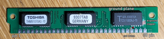
this also means that if you take a sharp hobby knife or the like and scrape away at the solder mask, you can expose or even cut the copper traces underneath, depending on whether you want to add or sever a connection somewhere.
Note that in this example (and in many other circuit boards) there's this very large and wide trace that covers most of the board where no other traces are present that I've labelled the ground plane - those are usually connected to either positive voltage or ground (in this case to ground via pins 9 and 22) and are used to provide easy access to either power or ground, plus their width means they can also pass much more current without overheating; in fact, if we were to compare this PCB to that of, say, a 100W+ something power supply...
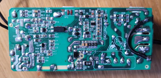
... you might notice the latter has some pretty beefy traces going around, especially towards the left and right ends of the PCB where the outputs and inputs respectively are located, due to the significant amounts of energy that might end up passing through those traces.
Meanwhile, most of the smaller traces and components are all primarily involved in regulating the behaviour of the larger and more powerful parts on the other side and therefore won't see all that much voltage or current. The big stuff is all topside and generally in contact with blocks of aluminium to act as heat sinks to prevent them from cooking themselves and releasing the magic smoke.
3 notes
·
View notes
Text
Circuit Board, PCB assembly & electronics manufacturing service provider from China (hitechcircuits.com)
What is a prototype PCB assembly?
PCB prototyping is the experimentation pilot stage of the product which is to be mass produced at a later stage. This is more of an experiment which is done after the initial discussions and the design. This offers a pre-production analysis of the boards that are to be manufactured, reducing the possible number of errors in the PCB design. PCB prototypes help the manufacturer analyze the strengths as well as weak areas of their proposed circuit boards. Prototypes also serve as a reference point for future versions of the same product. At Hitechpcba, we handle PCB prototype assembly in quantities from one to hundred printed circuit boards.
We have acquired capabilities that enable us to serve our clients better. All these years, we have worked on many complex prototype PCB assembly projects, and we believe the following capabilities have helped us serve our clients better.
Prototype PCB Assembly Services: We specialize in the following prototype printed circuit board assembly services.
SMT: We can provide single-sided and double-sided surface mount PCB assemblies in different specifications.
Plated Through Hole: We offer plated through hole assembly with selective soldering.
Mixed Assemblies: We often work on projects involving mixed assemblies – through-hole and SMT and electromechanical assemblies.
PCBA Testing: All the PCBA functional testing is performed in-house. Over the years, we have invested in various test fixtures and equipment, which helps us ensure the quality of PCBA. Currently, we provide the following types of PCBA testing services:
Flying probe testing for PCB
Functional testing including system and board-level testing
General PCB Assembly Capabilities: Our general PCB assembly capabilities are not limited to these:
RoHS, leaded or lead free, clean and no chemistries
PCB components including various types of QFNs, BGAs, 0105, 0201, 0804, and press fit components in small quantities.

What are the benefits of a prototype PCB assembly?
Prototype PCB assembly comes with several advantages. These benefits play a major role in the facilitation of your PCB manufacturing. Some of these benefits include:
Detection of Flaws Early
With prototype PCB, you will easily detect whatever flaws are present during the product’s development stages. This will allow you to solve the issues thereby saving you some money if you had gone ahead to make the production having the flaws in them.
If you go ahead to make changes during the production, there may be a need for more technicalities, and this may be expensive.
Testing of Each Component
With a prototype, you will be able to test all your system’s elements individually before you go ahead to set it up. You should do this because it is important especially for very complex projects composed of several parts that are PCB based.
When you validate each of these components, you will be able to identify those areas having issues that you should look into. This is the only way the project can function the right way.
Reduction in Total Costs
Utilizing the prototype bare PCB for any of your projects could go a long way in reducing what you’ll have spent in total for the project. With prototyping, you will be able to notice those errors in your project and then make corrections before you start the real production.
As soon as these flaws have been checked and rectified, then you may continue with the manufacturing of your Printed circuit boards in large quantities, thereby saving you unnecessary costs.
High-Quality PCBs
Why prototyping your PCB is important is to help you test if your project will function effectively. When we talk of testing, it involves the identification of errors present and then rectifying and making corrections to them.
Therefore, the eventual PCB after the prototyping will be of high quality that surely meets standards set internationally.
Less Turnaround Time
With prototype PCB assembly, you will be able to reduce the total time used in producing your printed circuit board. While making use of prototype printed circuit boards, you’ll be able to see the errors and then make corrections before you start the actual production.
Therefore, the eventual prototype will be free of defects. This implies that your PCBs will be produced quickly by your manufacturer.

What are the different types of prototype PCB assembly services you offer?
With years of market presence and experience, we specializes in the following prototype PCB assembly services.
Plated through-hole (PTH): We can provide the through-hole assembly with selective soldering.
Surface mount technology (SMT): We offer single-sided as well as double-sided SMT board assemblies in varied specifications.
Mixed Assemblies: Our experts often work on projects involving both PTH and SMT assemblies.
What are the types of testing Hitechpcba use for prototype PCB assembly?
Automated Optical Inspection (AOI): This is performed before and after the soldering to identify the component placement, presence, and solder quality.
X-ray Testing: In this type of testing, the operator relies on the X-ray images of the PCB to check the solder joints and lead-less components such as Quad Flat Packs and ball grid arrays, which are generally not visible to naked eyes.
In-Circuit Testing (ICT): This method is used to detect manufacturing defects by testing the electrical properties in the SMT Assembly.
These techniques help us ensure the reliability and accuracy of the circuit boards. In addition to this, it ensures a long operational life of equipment, minimal production losses, streamlined processes, and much more.
What are the capabilities Hitechpcba offer for prototype PCB assemblies?
We specialize in offering IPC compliant, and quick turn PCB assemblies. We are very particular about our scheduled deliveries and timelines, and we deliver without compromising the quality. Our PCBA capabilities are not limited to these. Here are some capabilities we offer through prototype PCB assemblies.
RoHS compliance
Stringent testing procedures
Device encapsulation
Full turnkey, partial turnkey, and kitted/consigned services
Assemblies using Surface Mount (SMT), Thru-hole, Mixed Technology (SMT/Thru-hole), Single and double-sided SMT/PTH, Large parts on both sides, BGA on both sides.
Do you perform a component analysis for prototype PCB assemblies?
Yes, we check the quality and performance of components before mounting them on the circuit boards. This is because a malfunctioning component can affect the performance of the entire circuit board assembly and also pose risks.
What is your standard turnaround time for a prototype PCB assembly?
Our turnaround time for standard applications is two weeks. This timeframe varies depending on the complexity of the applications. However, we are committed to offering quick turnaround times without compromising on quality, functionality, and accuracy, which offers our client a competitive advantage and reduced time to market. You can also request any emergency assistance or queries related to any type of PCB assembly. Our experts will assist you in all possible ways.
How is the cost of prototype PCB assembly estimated?
PCBA costing varies based on the different factors, such as PCBA parts, type of materials to be used, order quantity, and much more. We can also offer quotes and customization options once you share the detailed requirement with us.
We focus on quality and customer satisfaction over anything else. This has helped us build a long list of happy and satisfied customers. So, if you wish to partner with a manufacturer of prototype PCB assembly in China, then don’t hesitate to reach us. Our experts will assist you through all the phases of the prototype PCB assembly process. We look forward to making your experience with us better and memorable.
How to choose prototype pcb assembly manufacturer?
Our pcb prototype assembly service includes the sourcing of components. This allows you to concentrate on what you do best: layout design. We have a dedicated sourcing staff that coordinates with multiple suppliers and distributors to purchase electronic parts as per client requirements, and our staff completes these purchasing particulars in a most efficient manner. We have advanced processes for optimal selection of packaging (cut tape, tube, bulk, etc.) to reduce the total cost. Furthermore, we are capable of cross-referencing parts and even locating hard-to-find and obsolete parts. Customers can be rest assured that when Hitech Circuits substitutes components that they are high quality: we only use the electronic component numbers and manufacturers specified in the BOM. We will not modify your original layout design. Part substitutions take place only with your permission.
The final pcb prototype assembly service cost includes assembly labor charges, bare circuit board rates, and part costs. We understand the importance of prompt delivery. The sooner the components are sourced, the sooner we can begin circuit board fabrication. We thoroughly evaluate engineering inquiries and concerns related to the related parts with our clients before commencing circuit board assembly. The average time taken for pcb manufacturing assembly is about two weeks, which can be further reduced if there are no hard-to-locate components or documentation mistakes.
We have specialized experts to deliver fast turnarounds for prototype circuit board assembly with surface-mount (SMT), through-hole (THT) and mixed-technology components.
Anyone interested in electronics and electronic circuit boards needs to understand the various stages of developing and producing a printed circuit board. It can come in handy when you are seeking a top prototype smt assembly provider. The various production stages of printed circuit boards entail design, prototyping (prototype PCB development and rapid prototyping pcb assembly), and PCB high volume production. Different entities will always seek part of the whole production process depending on their electronic circuit board needs.
However, this article seeks to help you understand everything about prototype PCB assembly, a fundamental aspect of the PCB production process.
Rapid prototyping pcb assembly represents a fundamental phase of the printed circuit production process. It is also inferred as PCBA prototype assembly, SMT or surface-mount technology PCB prototype, PCB sample assembly, etc. From these alternative names, the meaning of prototype assembly regarding printed circuit boards becomes apparent. So what is assembly prototype?
PCB prototype assembly service is a fast prototype printed circuit board assembly primarily used to test fresh or new electronic designs. Consequently, it assists with checking and ensuring quality assurance of the PCB. For instance, it verifies that no bug exists in the test PCB, updates the design, and finds bugs. In most instances, prototype assembly of an electronic project will require two or three iterations to ensure everything is perfect.

Why Choose Hitech Circuits PCB Assembly for Your Prototype PCB Assembly Projects?
There are several PCB manufacturers specializing in prototype PCB assembly services. However, Hitech Circuits stands out owing to the following:
1.Strong Supply Chain: Over the years, we have built strong supply chain relationships in the industry, which helps us fulfill the requirements of turnkey prototype assembly services easily.
2.Fastest Turnaround Times: Our engineering expertise coupled with our understanding of industry requirements and a well-equipped facility enables us to assure the fastest turnaround times of 24-48 hours.
3.Reliability: All the printed circuit boards that we produce are IPC compliant, which helps us assure reliability.
4.Competitive Pricing and Quick Quote: Our supply chain relationships enable us to assure competitive prices. The cost of the PCB prototype assembly will be made available within 24-48 hours.
2 notes
·
View notes
Text
LV UPDI for basic ATtiny programming 🔌💻🔧

Part 2! We have been working a lot with attiny816 and attiny1616 chips (https://www.adafruit.com/search?q=attiny) lately, as for our seesaw boards. And we're often needing to program them with a CP2102-based breakout (https://www.adafruit.com/product/5335) with a 4.7K resistor soldered between the RX and TX pins. But we are hankering for a nicer programmer. One that can select 3V or 5V power and logic? Yesterday, we designed an HV programmer; today, we tore out a few parts for the 12V HV programming pulse and spun this simple 3/5V-only UPDI programming dongle. It's a lot like this adorable open-source hardware design (https://github.com/wagiminator/AVR-Programmer/tree/master/SerialUPDI_Programmer), and it inspired us to make something similar.
Instead of a USB A plug, going with USB C. Instead of the CH340N, we kept the CH340E because we like the 'activity' LED, assuming it works. for power, the classic 3.3V AP2112K LDO is kept… plus the 3/5V selection switch! We added a JST SH 3-pin to connect to a quick wire harness (https://www.adafruit.com/product/5755). It fits nicely on a single-sided PCB.
#adafruit#attiny#microcontroller#diyelectronics#programmingtools#hardwarehacking#embeddeddesign#techinnovation#circuitdesign#makercommunity#usbprogramming#electronicsproject
2 notes
·
View notes
Text
In developing any Electrical and Electronics System we must first conceptualize and design the circuit and then go to testing and debugging only after these two stages are complete, we go for final fabrication on the PCB. In all these three processes testing and debugging is the most important because here we ascertain that the circuit we developed is working as intended and there is no bugs in the system which might affect the performance of the device. In this stage we fabricate the circuit on the Breadboard or the Perfboard like this with the help of through hole package components to iron out kinks. It is made up of Fiber Glass which is extremely durable and flexible which makes it great to be used in final industry ready product. It has tin coating on holes at one side which allows you to design the PCB on single side only without having to worry about component placement on the board. It is extremely easy to work with and you can easily solder on this board as it has soldering spots and some gap between them to avoid short circuiting but still you need to take care while designing the circuit of these things.
3 notes
·
View notes
Text
PCB Fabrication Company in India – Reliable Solutions for Your Manufacturing Needs
Printed Circuit Boards (PCBs) are the foundation of modern electronics. From mobile devices to industrial equipment, PCBs are essential in powering technology across industries. As demand for high-quality electronics continues to rise, India has become a global hub for PCB fabrication, offering reliable, affordable, and advanced manufacturing solutions.

If you are looking for trusted PCB fabrication company in India, FindingMFG connects you with verified manufacturers ready to deliver quality at every stage of production.
Why Work with a PCB Fabrication Company in India?
India has established itself as a leading destination for electronics manufacturing. Supported by skilled professionals, modern infrastructure, and global certifications, Indian PCB manufacturers deliver products that meet international standards. Here’s why businesses choose PCB fabrication companies in India:
Affordable and Efficient Production
PCB manufacturers in India provide cost-effective solutions, whether you require a prototype or a large-volume order. Competitive pricing combined with strict quality control ensures that you receive reliable products at the right cost.
Advanced Manufacturing Capabilities
With access to modern machinery and production techniques, Indian PCB companies can fabricate single-sided, double-sided, and multilayer boards. They can handle standard designs as well as complex, custom configurations.
Customized Services for Every Requirement
Indian manufacturers specialize in tailored PCB solutions to match your exact project needs. From design specifications to delivery timelines, they offer flexibility for both small and large production runs.
Commitment to Global Standards
Leading PCB fabrication companies in India hold international certifications such as ISO, IPC, UL, and RoHS. These certifications guarantee that every board produced meets high-quality benchmarks for global markets.
Comprehensive PCB Fabrication Services
At FindingMFG, you can easily connect with PCB manufacturers offering a wide range of services, including:
Single-Sided PCBs
Double-Sided PCBs
Multilayer PCBs
Flexible and Rigid-Flex PCBs
High-Density Interconnect (HDI) PCBs
Metal Core PCBs
High-Frequency PCBs
Whether your project is straightforward or highly complex, India’s PCB manufacturers have the capabilities to deliver.
Industries Served by PCB Fabrication Companies in India
Indian PCB manufacturers serve a broad range of industries, including:
Automotive
Aerospace and Defense
Consumer Electronics
Telecommunications
Medical Devices
Industrial Automation
IoT and Smart Technology
This industry expertise allows them to provide solutions that meet the specific needs of diverse applications.
FindingMFG – Connecting You with the Right PCB Fabrication Partner
FindingMFG is India’s trusted online platform for sourcing electronics manufacturing services. We help you discover reliable, verified PCB fabrication companies in India, simplifying the process of finding the right supplier for your project.
What FindingMFG Offers:
Verified suppliers across India
Easy-to-use search filters
Fast, direct quote requests
Transparent communication with manufacturers
Solutions for domestic and international buyers
Start Your PCB Manufacturing Project Today
Choosing the right PCB fabrication partner is a critical step toward building successful electronic products. With FindingMFG, you gain access to India’s best manufacturers who can deliver quality, precision, and value.
Post your requirement on FindingMFG and connect with trusted PCB fabrication companies in India.
Visit FindingMFG.com to get started
#pcb fabrication company#pcb fabrication companies in India#pcb design#pcb manufacturing#manufacturing directory
0 notes
Text
LG Refrigerator Repair in Noida — Trusted Experts at Your Doorstep

If you have an LG refrigerator at your home in Noida and you're facing problems such as cooling failure, strange noise, water leakage, or unexpected power cuts, it's the right time to call a professional. A refrigerator is one of the most crucial appliances of your home, particularly for the hot and humid summers of Noida. When it malfunctions, it may disturb your daily routine, ruin your groceries, and cause unnecessary tension. That's where our expert LG Refrigerator Repair in Noida comes in — to offer you quick, dependable, and affordable solutions right at your doorstep.
Why Professional LG Refrigerator Repair in Noida?
It may be hazardous to try and repair a fridge yourself and could even result in additional damages. Our expert LG refrigerator repair service makes sure that your appliance is fixed by experienced technicians who deal with LG models exclusively. Irrespective of whether you own a single-door, double-door, side-by-side, or inverter LG fridge, our professionals are fully familiar with the system and can diagnose the fault accordingly in no time. We believe in delivering quality workmanship using authentic spare parts that ensure long-term performance and durability.
When you hire us for LG Refrigerator Repair in Noida, you are choosing peace of mind. We are dedicated to getting your fridge running like new, with as little interruption to your schedule as we can. We employ the most advanced diagnostic equipment and repair methods to get to the actual cause—permanently, not just the symptom.
Common LG Refrigerator Problems We Fix
With the passage of time, LG refrigerators can be infested with problems due to frequent wear and tear, voltage fluctuations, or improper maintenance. Some of the most commonly faced problems we get to hear are:
Refrigerator not cooling or overcooling
Freezer not freezing
Water leakage from inside or outside the fridge
Compressor making unusual sounds
Ice buildup in the freezer
Door handle or door gasket breaking
Power supply problems
Faulty thermostat or sensors
Regardless of how complicated the problem appears, our professional team for LG Refrigerator Repair in Noida is adequately prepared to correct it with precision and expertise.
Same-Day Doorstep Service Throughout Noida
We know how infuriating it is when your refrigerator suddenly malfunctions. That is why we provide same-day LG refrigerator repair in Noida in all the prominent areas such as Sector 15, Sector 62, Sector 137, Greater Noida West, and more. Just call us or book an appointment online, and our professionals will come to your doorstep equipped with the tools and spare parts.
Our experts are trained to be proficient so that the fixing is done primarily in one visit. We practice an open policy of pricing — no hidden fees, no replacing anything beyond what is needed, and no upselling. With our doorstep delivery, you do not need to lift your heavy fridge even one step. Just relax and let the experts do everything for you.
Authentic LG Parts and Warranty Support
Without a doubt, the number one concern that people have with appliance repair is spare part quality. We only install 100% original LG spare parts to make your refrigerator last as long as new for decades to come. Whether it's the compressor, thermostat, fan motor, or PCB, every part is sourced from reputable LG-authorized dealers.
We also offer a service guarantee, by which you can have more trust in our repair service. If the same problem occurs again within the guarantee period, we will repair it at no cost. This commitment to quality is what differentiates our LG Refrigerator Repair in Noida from others.
Transparent and Reasonable Pricing
Our LG refrigerator repair in Noida is made affordable for small families and large families alike. We use flat rate pricing upon diagnosis so you know precisely how much you are paying. No hidden bills, and prices are competitive, with the local market and standards of services in mind.
We believe that quality appliance repair does not have to cost a fortune. That is why we ensure to provide quality while keeping the costs as minimum as possible. Whether it's a small repair or an entire replacement of a major component, you can rely on us to provide reasonable prices and authentic repair services.
Book Your LG Fridge Repair in Noida Now
Don't let a faulty refrigerator interrupt your daily life or waste your groceries. With our expert LG Refrigerator Repair in Noida, help is just a call away. We’re committed to delivering the best repair service with fast turnaround time, professional technicians, and a satisfaction guarantee.
To schedule your appointment, just log in to our website or give us a call. Inform us of your area, fridge model, and problem, and we will send over the most suitable expert for the task. Let us handle your refrigerator while you focus on what matters most — your home and family.
0 notes
Text

Rigid-flex PCB: A flexible area of appropriate length needs to be designed between the rigid areas to reduce stress and reduce manufacturing complexity; unattached single-sided flexible boards are softer than double-sided boards.
#pcb#flex pcb#rigid-flex pcb#flex circuit pcb#flexible pcb board#flexible circuit board#fpcway#fpcway.com#www.fpcway.com#today on tumblr
0 notes
Text

EXCERIA Plus G4 rappresenta la quarta generazione della serie mainstream di KIOXIA, introducendo il supporto PCIe 5.0 attraverso un'architettura DRAM-less che distingue questo drive dalla maggior parte dei competitor. La combinazione tra il controller Phison PS5031-E31T e la memoria BiCS8 218-layer 3D TLC crea una soluzione che punta sull'equilibrio piuttosto che sulle prestazioni estreme, con risultati che possono soddisfare alcuni utenti ma deludere chi cerca le massime velocità. Unboxing e prime impressioni: minimalismo funzionale L'esperienza di unboxing rivela immediatamente l'approccio pragmatico di KIOXIA verso il segmento mainstream-enthusiast. La confezione, essenziale ma curata, presenta il caratteristico design bianco e argento che contraddistingue il brand. All'interno, oltre al drive da 2TB, troviamo la documentazione essenziale e l'accesso al software SSD Utility per la gestione e il monitoraggio delle prestazioni. Il primo impatto visivo con l'unità rivela un design single-sided estremamente pulito e funzionale. La superficie presenta un'estetica minimale con l'inconfondibile logo KIOXIA, mentre l'assenza di dissipatori integrati testimonia l'approccio orientato all'efficienza termica intrinseca del progetto. Questa scelta progettuale consente una compatibilità universale anche con i sistemi più compatti. Le dimensioni standard M.2 2280 (80.15 x 22.15 x 2.38 mm) e il peso contenuto di soli 5.7 grammi confermano la versatilità di installazione, mentre la qualità costruttiva rivela l'esperienza decennale di KIOXIA nella produzione di memorie flash. La superficie del PCB presenta una finitura industriale che ispira fiducia nella durabilità a lungo termine. Attualmente è disponibile sulla pagina ufficiale di Amazon Italia. Materiali e costruzione: l'innovazione DRAM-less L'analisi della costruzione rivela scelte ingegneristiche coraggiose che distinguono questo SSD dalla concorrenza. Il cuore del sistema è rappresentato dal controller Phison PS5031-E31T, primo controller PCIe 5.0 specificamente progettato per architetture DRAM-less. Questa scelta non è un compromesso economico, ma una decisione strategica che permette di raggiungere prestazioni elevate riducendo consumi e costi. La memoria NAND BiCS8 a 218 strati rappresenta una delle implementazioni più avanzate della tecnologia 3D TLC attualmente disponibile. Sviluppata interamente da KIOXIA in Giappone, questa memoria offre densità superiore, latenze ridotte e affidabilità migliorata rispetto alle generazioni precedenti. La struttura a strati verticali permette una gestione ottimizzata dello spazio e delle prestazioni. L'architettura DRAM-less merita un approfondimento particolare. Mentre molti competitor utilizzano cache DRAM dedicata, KIOXIA ha optato per una soluzione che sfrutta l'Host Memory Buffer (HMB) del sistema. Questa tecnologia permette al controller di utilizzare una porzione della RAM di sistema come cache, riducendo costi e consumi senza penalizzare significativamente le prestazioni nell'uso quotidiano. Il supporto NVMe 2.0c garantisce compatibilità con le tecnologie più recenti, incluse le ottimizzazioni per gaming e applicazioni professionali. L'implementazione delle specifiche GPIO, UART e I3C/I2C nel controller offre flessibilità per future implementazioni e personalizzazioni. Design termico: efficienza come paradigma Mentre molti competitor richiedono dissipatori voluminosi o ventole attive, KIOXIA ha sviluppato una soluzione che opera senza throttling termico anche in configurazioni passive, grazie al consumo di soli 5.3W sotto carico massimo. Questa efficienza energetica, che rappresenta un miglioramento dell'80% rispetto alla generazione precedente, deriva dalla combinazione di fattori progettuali innovativi. Il controller E31T, ottimizzato per PCIe 5.0, gestisce i flussi di dati in modo più efficiente, mentre l'architettura DRAM-less elimina il consumo aggiuntivo della cache dedicata. Le etichette innovative per la dissipazione del calore applicate al drive contribuiscono alla gestione termica passiva, distribuendo uniformemente il calore generato durante le operazioni intensive. Il risultato è un'operatività stabile nell'intervallo 0°C-85°C senza necessità di raffreddamento attivo nella maggior parte delle configurazioni. Durante i test prolungati, il drive ha dimostrato di mantenere prestazioni consistenti anche sotto stress termico, confermando l'efficacia del design orientato all'efficienza. Questa caratteristica lo rende ideale per laptop, sistemi compatti e configurazioni con ventilazione limitata. Specifiche tecniche: prestazioni bilanciate La connettività PCIe 5.0 x4 sfrutta appieno la banda passante disponibile, permettendo velocità teoretiche che rappresentano un significativo passo avanti rispetto alla generazione PCIe 4.0. Le velocità sequenziali dichiarate raggiungono 10.000 MB/s in lettura e 8.200 MB/s in scrittura per il modello da 2TB, valori che posizionano il drive nella fascia alta del segmento consumer. Il modello da 1TB mantiene la stessa velocità di lettura con una leggera riduzione in scrittura a 7.900 MB/s. Le prestazioni casuali sono specificate fino a 1.300.000 IOPS in lettura e 1.400.000 IOPS in scrittura, parametri che garantiscono una reattività eccellente nelle operazioni quotidiane. Questi valori, benché inferiori ai competitor con cache DRAM, risultano più che sufficienti per la stragrande maggioranza degli utilizzi. La durabilità è garantita da specifiche di resistenza competitive: 600 TB per il modello da 1TB e 1.200 TB per il 2TB. Questi valori, basati sugli standard JEDEC, rappresentano anni di utilizzo intensivo prima di raggiungere i limiti teorici di scrittura. Prestazioni reali: efficienza in azione Per valutare le prestazioni reali dell'EXCERIA Plus G4, i test sono stati condotti sulla stessa configurazione hardware utilizzata per precedenti analisi: Configurazione di test: Processore: AMD Ryzen 9 7950X (16-core) a 5500 MHz Scheda madre: MSI X670E Gaming Plus WiFi (MS-7E16) Scheda video: NVIDIA GeForce RTX 5080 (16GB) Questa piattaforma rappresenta un ambiente ideale per testare un drive PCIe 5.0, offrendo il pieno supporto allo standard più recente e eliminando qualsiasi possibile collo di bottiglia hardware. I test sono stati condotti su un'unità completamente vuota (0% di riempimento), condizione ottimale per valutare le prestazioni massime teoriche. I risultati dei benchmark confermano l'approccio bilanciato di KIOXIA. Le velocità di lettura sequenziale raggiungono picchi di 10.365 MB/s nei test ottimali, superando le specifiche dichiarate e dimostrando l'efficacia dell'architettura implementata. Questo si traduce in tempi di caricamento ridotti per applicazioni e giochi di grandi dimensioni. Le prestazioni di scrittura sequenziale toccano i 8.593 MB/s nelle condizioni ideali, avvicinandosi alle specifiche teoriche e confermando la solidità del sistema di gestione della memoria flash. Anche durante operazioni prolungate, il drive mantiene prestazioni elevate grazie alla gestione termica efficiente. I test con AS SSD Benchmark mostrano risultati più conservativi ma rappresentativi dell'utilizzo reale, con 7.571 MB/s in lettura e 7.767 MB/s in scrittura sequenziali, accompagnati da un punteggio complessivo di 10.941. I tempi di accesso risultano competitivi: 0.022 ms in lettura e 0.017 ms in scrittura. Velocità di scrittura e lettura: consistenza e affidabilità L'analisi dettagliata delle velocità di trasferimento attraverso benchmark rigorosi rivela il carattere dell'EXCERIA Plus G4. I test condotti con CrystalDiskMark in diverse configurazioni mostrano prestazioni che variano in base al carico di lavoro, riflettendo il comportamento di un drive ottimizzato per l'efficienza. Le letture sequenziali mostrano eccellente consistenza, con valori che oscillano tra 7.481 MB/s e 10.365 MB/s a seconda delle condizioni di test. Le prestazioni migliori si ottengono con file di dimensioni ottimali, mentre carichi di lavoro misti possono mostrare variazioni che riflettono la gestione dinamica della cache. Le scritture sequenziali raggiungono picchi di 8.593 MB/s nel test ottimale, con valori che si stabilizzano intorno ai 4.700-4.800 MB/s in condizioni più realistiche. Questa variazione è tipica dei drive DRAM-less, che gestiscono la cache in modo dinamico adattandosi al carico di lavoro. Le prestazioni casuali 4K mostrano 733-746 MB/s in lettura e 532-541 MB/s in scrittura nei test Q32T1, valori competitivi che garantiscono una reattività del sistema eccellente. I test single-thread Q1T1 registrano 88-90 MB/s in lettura e 268-289 MB/s in scrittura, prestazioni che si traducono in un'esperienza utente fluida. La validazione attraverso AS SSD Benchmark conferma la solidità delle prestazioni con risultati che, pur non raggiungendo i picchi di CrystalDiskMark, dimostrano la consistenza dell'architettura implementata. Il rapporto prestazioni-efficienza risulta tra i migliori della categoria PCIe 5.0. Compatibilità e installazione: universalità garantita L'implementazione dello standard M.2 2280 garantisce compatibilità universale con la stragrande maggioranza delle piattaforme moderne. La retrocompatibilità con slot PCIe 3.0 e 4.0 assicura funzionalità anche su sistemi meno recenti, sebbene con prestazioni limitate dalla banda passante disponibile. L'installazione risulta immediata grazie al design single-sided che elimina problemi di clearance anche nei sistemi più compatti. L'assenza di dissipatori integrati rende il drive ideale per laptop e sistemi con vincoli termici, mentre la compatibilità con PlayStation 5 e Xbox Series X/S ne espande l'utilizzo al gaming console. Il supporto software attraverso SSD Utility offre strumenti completi per il monitoraggio delle prestazioni, la gestione della salute del drive e l'ottimizzazione delle impostazioni. Le funzionalità TRIM, garbage collection e Host Memory Buffer vengono gestite automaticamente per ottimizzare le prestazioni nel tempo. Efficienza energetica: il vero punto di forza Con un consumo di soli 5.3W sotto carico massimo e 50mW in idle, il drive stabilisce nuovi standard per il segmento PCIe 5.0, dove competitor possono richiedere fino a 19W sotto stress. Questa efficienza si traduce in vantaggi concreti: maggiore autonomia per i laptop, riduzione del calore generato nei sistemi desktop, e minori costi operativi per utilizzi intensivi. Il design DRAM-less contribuisce significativamente a questi risultati, eliminando il consumo aggiuntivo delle cache dedicate. L'operatività passive senza necessità di raffreddamento attivo rappresenta un ulteriore vantaggio, permettendo installazioni in sistemi con ventilazione limitata senza compromettere le prestazioni. Questa caratteristica è particolarmente apprezzata in ambiti professionali e workstation silenziose. Confronto con la concorrenza: posizionamento strategico Rispetto a competitor come il Samsung 990 PRO o Kingston FURY Renegade G5, offre un rapporto prestazioni-efficienza superiore. Il confronto con drive tradizionali con cache DRAM mostra prestazioni sequenziali competitive ma con un vantaggio significativo in termini di consumi ed efficienza termica. La differenza nelle prestazioni casuali intensive risulta trascurabile nell'utilizzo quotidiano, mentre i vantaggi in efficienza sono immediatamente percepibili. La proposta di valore dell'EXCERIA Plus G4 risulta particolarmente competitiva nel segmento mainstream-enthusiast. Il prezzo contenuto, la garanzia quinquennale e l'approccio eco-friendly ne fanno una scelta razionale per utenti consapevoli che non vogliono sacrificare le prestazioni. Scenari d'uso: versatilità moderna Il gaming moderno rappresenta uno degli scenari d'uso più naturali per questo drive. I giochi di ultima generazione, con asset sempre più voluminosi, beneficiano delle velocità di caricamento ridotte, mentre l'efficienza energetica risulta particolarmente apprezzata nei sistemi gaming compatti e nelle configurazioni ITX. Il content creation trova nell'EXCERIA Plus G4 un alleato affidabile per editing video 4K, manipolazione di file RAW e rendering. Le prestazioni sequenziali elevate accelerano i workflow più comuni, mentre l'efficienza termica permette sessioni di lavoro prolungate senza throttling. Gli utenti professionali apprezzano la combinazione di prestazioni e affidabilità per applicazioni di produttività, virtual machine e database. La consistenza delle prestazioni nel tempo e l'efficienza energetica rappresentano vantaggi concreti per utilizzi intensivi in ambito aziendale.I sistemi mobile beneficiano enormemente dell'efficienza energetica superiore, che si traduce in autonomia estesa e minor calore generato. La compatibilità universale rende il drive ideale per upgrade di laptop gaming e workstation portatili. Considerazioni finali: l'equilibrio perfetto Il KIOXIA EXCERIA Plus G4 rappresenta un approccio maturo e consapevole al segmento PCIe 5.0, dimostrando che è possibile ottenere prestazioni elevate senza compromettere efficienza e sostenibilità. L'architettura DRAM-less, lungi dall'essere un compromesso, si rivela una scelta strategica che offre vantaggi concreti nella maggior parte degli scenari d'uso. Le prestazioni offerte, con velocità che raggiungono i 10.365 MB/s in lettura e 8.593 MB/s in scrittura, posizionano il drive nella fascia alta del segmento consumer, mentre l'efficienza energetica di soli 5.3W sotto carico stabilisce nuovi standard per la categoria. La compatibilità universale e il prezzo competitivo completano un quadro estremamente attraente. Per gamer consapevoli, professionisti dell'editing e utenti mobile che cercano il giusto equilibrio tra prestazioni e sostenibilità, l'EXCERIA Plus G4 da 2TB rappresenta una scelta razionale e lungimirante. La combinazione di tecnologie innovative, efficienza superiore e affidabilità consolidata ne fa un investimento che continuerà a soddisfare le aspettative per anni. Il futuro dello storage efficiente è arrivato, e porta il nome di KIOXIA EXCERIA Plus G4. Un drive che dimostra come l'innovazione tecnologica possa andare di pari passo con la responsabilità ambientale, offrendo prestazioni da enthusiast con l'efficienza che il mercato moderno richiede. Attualmente è disponibile sulla pagina ufficiale di Amazon Italia. Read the full article
0 notes
Text
PCB Design Driven by Precision, Practicality and Performance

At Arrival Electronics Limited, we understand that PCB design isn’t just a step in product development—it’s the foundation that supports every component, signal path, and functionality. Whether you're developing a next-generation medical device, a robust industrial control unit, or a compact consumer electronic product, our role is to ensure your ideas are backed by dependable, efficient, and expertly engineered printed circuit boards.
With decades of hands-on experience in electronics, our team has worked with companies across multiple industries, helping bring projects to life—from concept through to production.
In this article, we’ll share what makes a strong design, the practical elements that often go unnoticed, and how our services help keep your project moving forward from the drawing board to delivery.
Why PCB Design Matters
Designing the right board isn't just about connecting components—it's about ensuring the entire electrical system performs reliably, consistently, and within its intended environment. A well-thought-out layout contributes to:
Product longevity and durability
Efficient power consumption
Signal integrity and reduced noise
Thermal control and mechanical stability
Overlooking critical details during this stage can lead to performance issues, unnecessary rework, or even total product failure. We take every aspect seriously to help our clients avoid costly missteps and stay on track.
What Makes a Solid Design?
Over the years, we’ve found that strong board design depends on more than just software skills or technical knowledge. It’s about having the awareness to balance practical considerations with real-world requirements. Here’s what we focus on in every project:
1. Clear Design Objectives
Before a single trace is laid out, we work closely with you to understand the end-use of the product. Is it intended for a high-vibration environment? Will it operate at high frequency? These questions shape everything from component selection to board layout.
2. Efficient Layout and Routing
We pay close attention to the physical layout, making sure component placement allows for clean, short signal paths and minimal electromagnetic interference. Where needed, we apply differential pair routing, impedance control, and strategic layer stacking.
3. Manufacturability
A design that’s difficult to produce can quickly eat into budgets and timelines. We align our designs with your manufacturing capabilities—choosing standard sizes, spacing, and materials that avoid bottlenecks in production.
4. Thermal Management
Heat can quietly cause long-term damage. We integrate copper pours, thermal vias, and heat sinks when necessary, ensuring temperature-sensitive components stay within safe operating ranges.
5. Design for Testability
We keep diagnostics in mind from the outset. Well-placed test points and clearly labelled nets allow engineers to easily validate performance and troubleshoot issues during development.
Our Approach
What sets us apart is the level of care and accountability we bring to each project. We don’t treat board design as a one-size-fits-all task. Instead, we tailor our process to match your product’s specific technical and commercial requirements.
Collaborative from the Start
We believe good design starts with good communication. Our team begins by understanding your specifications, timelines, and constraints. If needed, we assist with component selection and design reviews, helping guide decisions that support project success long-term.
In-House Expertise
Our engineers bring decades of collective experience across RF design, digital and analogue electronics, signal integrity, and power distribution. This depth of expertise means we’re equipped to handle both complex multilayer PCBs and simpler single-sided designs with the same level of detail and reliability.
Detailed Documentation
We provide comprehensive documentation for every design, including Gerber files, BOMs, assembly drawings, and test documentation. Everything is clearly structured, so your production team or manufacturer has what they need to get started without delay.
Supporting Every Stage of Development
We understand how interconnected the design process is with the rest of the product lifecycle. That’s why our support doesn’t end once the board layout is finished.
Prototyping
We help bridge the gap between design and validation by assisting with prototype builds. If changes are needed, we provide quick iterations without compromising design integrity.
Compliance
Many products need to meet specific regulatory standards. Our knowledge of EMC, safety, and industry certifications helps keep your project aligned with compliance from the ground up.
Component Availability
Supply chain challenges can affect even the most carefully engineered layouts. We actively review component availability early in the process and suggest practical alternatives when necessary. This helps keep your project on schedule and reduces the risk of unexpected delays.
A Closer Look at Our Capabilities
Here’s a snapshot of the types of board layout work we handle:
Single-sided and double-sided configurations
Multilayer builds (up to 24 layers)
High-speed digital and analog signal routing
RF and microwave applications
Flexible and rigid-flex formats
Power distribution and regulation paths
Projects with tight impedance and signal integrity demands
All layouts are created using industry-standard tools, including Altium Designer and Cadence Allegro, ensuring smooth integration with your existing workflows.
Industries We Serve
One of the strengths of our team is our versatility. We’ve worked with clients across sectors including:
Medical Technology: Supporting devices that require extreme reliability and precise electrical behavior.
Industrial Automation: Creating robust PCBs for use in high-temperature, high-vibration environments.
Consumer Electronics: Helping bring compact and functional designs to market faster.
Automotive: Designing for safety, efficiency, and long-term performance in vehicle systems.
Telecommunications: Handling high-frequency signal requirements and tight timing constraints.
No matter the application, we bring the same level of care and engineering discipline to every project.
Focused on Accuracy
Every layout we deliver goes through rigorous design rule checks (DRC), electrical rule checks (ERC), and internal peer reviews. We follow industry best practices and adapt our quality assurance process to meet the specific standards of your sector.
We’ve earned the trust of clients across the UK by consistently delivering high-quality work with a personal touch. Our focus is on making your project a success—not just through technical execution, but through reliability, responsiveness, and genuine collaboration.
Common Challenges We Help Solve
If you’ve experienced any of the following issues, we’re here to help:
Designs that aren’t manufacturable without rework
Unstable prototypes or unexpected signal behaviour
Thermal problems during test or usage
Poor EMI performance or compliance failures
Designs delayed by long lead-time components
The Edge of Partnering With Us
There are many design services out there. What makes us different is the way we treat our clients and the projects they entrust to us. When you work with us, you get more than a technical service—you gain a partner who’s committed to your success.
We listen. Your needs guide every design decision we make.
We respond quickly. Tight timelines don’t faze us—we’re used to working in dynamic environments.
We follow through. From first sketch to final sign-off, we’re with you every step of the way.
Whether you’re a start-up developing your first prototype or an established manufacturer needing dependable support for your next product line, we bring the right mix of experience, care, and clarity to help you move forward.
Let’s Begin Your Project
IIf you're looking for dependable design services with a team that understands the real-world pressures of product development, we’re here for you at Arrival Electronics Limited. Our process is built around clear communication, careful planning, and engineering you can trust, including expert PCBA services to ensure every component is perfectly integrated.
We’re more than just a distributor—we’re your engineering partner. From bespoke solutions to component sourcing and full system support, we’re here to help turn your vision into reality.
For more about our services or to start a conversation, visit arrivalelectronics.co.uk.
0 notes
Text
Learn the Traits to Find the Best Mcpcb Manufacturer for Your Needs
Metal-core printed circuit boards are one of the most significant spare parts you need to operate and control electronic goods. The quality of this spare will affect the functioning of the entire device. Hence, the manufacturers and the suppliers of the product are some of the elemental stakeholders for electronic device-producing brands. Naturally, due to massive demand, you can find several makers and suppliers in the industry. In this article, we will discuss the traits to discern the best.
Years of experience
The first aspect which you must find out to work with the best mcpcb manufacturer is the number of years for which the company has been operational in the market. You must look for a brand which has been in the market for a minimum of one and a half decades.
Service Array
Services from the top manufacturers and suppliers can help patrons get the best value for their investment. Some of the vital services you can get from the market leaders is mcpcb assembly, mass production, product prototype and innovative designing. These brands are masters in customization and they can change and adapt their products as per the precise customer requirements.
Product Array
Apart from service variety these brands can also act as some of the best single window service providers for different products like single layer metal core pcb, double sided metal core pcb, two layer aluminum base pcb and multilayer aluminum base pcb. Hence irrespective of your requirement specifications you can turn to a single vendor to meet all your business needs.
Quality control certificate
Finally, before you select a vendor for your business one of the main things which you must check is quality assurance certifications for the products from the vendor. This is one of the parameters that give you assurance for the product quality into which you are investing and also for their internal procedures and organization culture. These are the vendors who can add much value to your business.
0 notes
Text
AVR HV UPDI FTW!
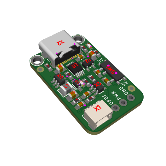
We have been working a lot with attiny816 and attiny1616 chips (https://www.adafruit.com/search?q=attiny) lately, as for our seesaw boards. We often must program them with a CP2102-based breakout (https://www.adafruit.com/product/5335) with a 4.7K resistor soldered between the RX and TX pins. But we are longing for a nicer programmer. Perhaps one that can select 3V or 5V power and logic? And activity LED? and 12V High Voltage programming support if we accidentally set the HV-Only fuse? We looked around and found this charming open-source hardware design (https://github.com/wagiminator/AVR-Programmer/tree/master/SerialUPDI_HV_Programmer), and it inspired us to make something similar.
Instead of a USB A plug, going with USB C. We've used the CH9102F (https://www.adafruit.com/product/5568) but never the CH340E, but it seems like it will do the job here. The classic 3.3V AP2112K LDO is kept for power, and the MT3806 booster looks neat, so that goes on too… plus the 3/5V selection switch! The most significant change is going with a COS4561 analog switch for the 12V/UART signal swapping and a JST SH 3-pin for connecting a quick wire harness (https://www.adafruit.com/product/5755). It fits nicely on a single-sided PCB; most of the space goes to the booster and analog switch, so we'll make a non-HV version.
#attiny816#attiny1616#electronicsDIY#CP2102Breakout#seesawBoards#UPDIProgramming#OpenSourceHardware#USBCTech#SerialProgramming#CircuitDesign
3 notes
·
View notes
Text
PCB Manufacturing: A Comprehensive Guide to Printed Circuit Board Production

Introduction to PCB Manufacturing
PCB manufacturing is the process of creating printed circuit boards, which are essential components in nearly all modern electronic devices. From smartphones to industrial machinery, PCBs provide the foundation for electrical connections and component mounting. This guide explores the PCB manufacturing process, materials, technologies, and applications.
The PCB Manufacturing Process
1. Design and Schematic Creation
Before production begins, engineers design the PCB using specialized software like Altium Designer, KiCad, or Eagle. The design includes:
Schematic diagrams (circuit connections)
Component placement
Trace routing (copper pathways)
Layer stack-up (for multi-layer PCBs)
Once the design is finalized, a Gerber file (standard PCB manufacturing file) is generated for fabrication.
2. Material Selection
The base material of a PCB is typically FR-4, a flame-resistant fiberglass epoxy laminate. Other materials include:
Flexible PCBs: Made from polyimide for bendable circuits.
High-frequency PCBs: Use Rogers material for RF applications.
Metal-core PCBs: Aluminum or copper for heat dissipation.
3. Printing the Circuit Pattern
The PCB design is transferred onto the board using one of these methods:
Photolithography: A UV-sensitive photoresist is applied, exposed to UV light, and developed to create the circuit pattern.
Direct Imaging: A laser directly etches the pattern onto the PCB.
4. Etching the Copper Layers
After the circuit pattern is printed, the unwanted copper is removed through chemical etching. The remaining copper forms the conductive traces.
5. Drilling Holes for Components
Precision CNC machines drill holes for through-hole components and vias (connections between layers).
6. Plating and Copper Deposition
The drilled holes are electroplated with copper to ensure conductivity between layers.
7. Solder Mask Application
A solder mask (usually green) is applied to protect the copper traces and prevent short circuits. Openings are left for soldering components.
8. Silkscreen Printing
Text, logos, and component labels are printed on the PCB using silkscreen ink for easy assembly and identification.
9. Surface Finish Application
A surface finish is applied to protect exposed copper and improve solderability. Common finishes include:
HASL (Hot Air Solder Leveling)
ENIG (Electroless Nickel Immersion Gold)
OSP (Organic Solderability Preservative)
10. Electrical Testing and Quality Control
Each PCB undergoes automated optical inspection (AOI) and electrical testing to ensure functionality. Defective boards are rejected.
Types of PCBs in Manufacturing
1. Single-Layer PCBs
Simplest and most cost-effective.
Used in basic electronics like calculators.
2. Double-Layer PCBs
Conductors on both sides.
Common in consumer electronics.
3. Multi-Layer PCBs
4+ layers for complex circuits (e.g., motherboards).
Requires precise PCB manufacturing techniques.
4. Flexible PCBs
Used in wearables and medical devices.
Made from bendable materials.
5. Rigid-Flex PCBs
Combines rigid and flexible sections.
Ideal for aerospace and military applications.
Advanced PCB Manufacturing Technologies
1. High-Density Interconnect (HDI) PCBs
Features microvias and finer traces.
Used in smartphones and compact devices.
2. Embedded Components
Passive components (resistors, capacitors) are embedded within the PCB.
Reduces size and improves performance.
3. 3D Printed Electronics
Emerging technology for rapid prototyping.
Combines additive manufacturing with conductive inks.
Applications of PCB Manufacturing
PCBs are used in nearly every industry, including:
Consumer Electronics (Smartphones, Laptops)
Automotive (ECUs, Infotainment Systems)
Medical Devices (Pacemakers, Imaging Systems)
Aerospace & Defense (Avionics, Radar Systems)
Industrial Automation (Robotics, Control Systems)
Challenges in PCB Manufacturing
Miniaturization: Shrinking component sizes demand precision.
High-Speed Signal Integrity: Ensuring minimal interference.
Thermal Management: Preventing overheating in dense circuits.
Environmental Regulations: Compliance with RoHS and REACH.
Future Trends in PCB Manufacturing
AI-Driven Design Optimization
Sustainable Materials (Biodegradable PCBs)
5G and IoT Integration (Higher frequency PCBs)
Automated Smart Factories (Industry 4.0)
Conclusion
PCB manufacturing is a complex yet vital process that powers modern electronics. From design to testing, each step requires precision and expertise. As technology advances, printed circuit boards will continue to evolve, enabling smaller, faster, and more efficient devices.
Whether you're an engineer, hobbyist, or industry professional, understanding PCB manufacturing helps in designing better electronic products for the future.
1 note
·
View note
Text
PCB Manufacturers in India: Powering the Future of Electronics
India is steadily emerging as a key global player in the electronics industry, with Printed Circuit Board (PCB) manufacturing at its core. PCBs form the essential backbone of every electronic device, from smartphones and laptops to advanced defense systems and electric vehicles.
As the electronics sector in India continues to thrive, PCB manufacturers in India are expanding their capabilities, delivering high-quality, cost-effective solutions to meet both domestic and global demands. This article explores India’s PCB manufacturing ecosystem and highlights some of the leading companies driving this growth.
Why PCB Manufacturers in India Are in High Demand
The growth of PCB manufacturing company in India is driven by several significant factors:
Government Initiatives
Government programs such as Make in India and the Production Linked Incentive (PLI) Scheme have provided a major boost to the electronics manufacturing sector, encouraging domestic PCB production and reducing dependency on imports.
Rising Electronics Consumption
The increasing use of electronics in industries such as automotive, telecom, defense, consumer appliances, and renewable energy has created a surging demand for quality PCB fabrication.
Competitive Advantage
Indian PCB manufacturers combine cost-effectiveness, skilled engineering, and adherence to international quality standards, making them competitive not just in India but also in international markets.
Export Capabilities
Many Indian PCB companies now actively export to global markets, particularly in Europe, the United States, and Southeast Asia, expanding India’s presence in the international supply chain.
Leading PCB Manufacturers in India
Below is a curated list of some of the top PCB manufacturers in India, known for their expertise, innovation, and commitment to quality:
AT&S India Pvt. Ltd.
Location: Nanjangud, Karnataka AT&S India, a subsidiary of Austria-based AT&S Group, specializes in advanced high-density interconnect (HDI) and multilayer PCBs, catering to automotive, industrial, and medical device industries.
Shogini Technoarts Pvt. Ltd.
Location: Pune, Maharashtra With over four decades of experience, Shogini Technoarts focuses on single-sided and double-sided PCBs, supplying sectors like automotive, telecom, and lighting.
Genus Electrotech Ltd.
Location: Gandhidham, Gujarat Genus Electrotech is a leading fully integrated electronics manufacturer producing PCBs alongside complete electronics assemblies, widely used in energy meters, LED lighting, and automotive electronics.
Circuit Systems India Ltd. (CSIL)
Location: Gandhinagar, Gujarat CSIL manufactures multilayer PCBs for industries such as telecommunications, aerospace, automotive, and consumer electronics, known for precision and high reliability.
Anand Electronics
Location: Bengaluru, Karnataka Anand Electronics produces single, double, and multilayer PCBs, catering to customers in automation, LED lighting, power electronics, and industrial systems.
Meena Circuits Pvt. Ltd.
Location: Gandhinagar, Gujarat Meena Circuits specializes in multilayer PCBs and metal core PCBs (MCPCBs), supporting power electronics, automotive components, and LED applications.
Hi-Q Electronics Pvt. Ltd.
Location: Mumbai, Maharashtra Hi-Q Electronics offers customized PCB solutions, including flexible and rigid-flex PCBs, for sectors such as aerospace, defense, medical devices, and industrial machinery.
Epitome Components Ltd.
Location: Aurangabad, Maharashtra One of India’s largest producers of single-sided PCBs, Epitome Components supplies to major OEMs in the consumer electronics and lighting sectors both domestically and internationally.
Fine-Line Circuits Ltd.
Location: Mumbai, Maharashtra Fine-Line specializes in prototype and production PCBs, especially multilayer rigid PCBs, for demanding applications in defense, aerospace, and telecommunications.
SFO Technologies (NeST Group)
Location: Kochi, Kerala Part of the global NeST Group, SFO Technologies provides advanced PCB fabrication services, serving high-end industries such as aerospace, defense, medical, and industrial electronics worldwide.
Benefits of Choosing PCB Manufacturers in India
Selecting PCB manufacturers in India offers businesses several clear advantages:
International Certifications: Most Indian manufacturers are certified with ISO, UL, IPC, and RoHS standards.
Wide Range of Capabilities: From single-sided to multilayer, flexible, and HDI PCBs.
Engineering Support: Many manufacturers provide design support, prototyping, and customization.
Global Reach: Indian manufacturers export to several developed markets, showcasing reliability and trustworthiness.
The Road Ahead for PCB Manufacturing in India
As India continues to strengthen its electronics manufacturing ecosystem, the PCB industry will play a vital role in achieving self-reliance and reducing imports of critical components. With investments in automation, advanced machinery, and sustainable manufacturing practices, Indian PCB manufacturers are well-positioned to meet global demand.
Conclusion: Partner with the Best PCB Manufacturers in India
Whether you are designing innovative IoT solutions, building critical EV systems, or developing specialized equipment for aerospace or defense, India’s PCB manufacturers can provide world-class solutions tailored to your needs.
If you’re searching for reliable and experienced PCB manufacturing partners, explore the top suppliers on FindingMFG. Connect with trusted PCB fabrication companies and accelerate your product development journey.
Visit FindingMFG.com today to discover the leading PCB manufacturers in India for your next project
0 notes