#i2c-stemma-qt
Explore tagged Tumblr posts
Visit Tumblr Blog
Explore Tumblr blogs with no restrictions, modern design and the best experience.
Last Seen Tumblr Blogs


Fun Fact
In 2020, 44% of users from Denmark used Tumblr daily.
Text
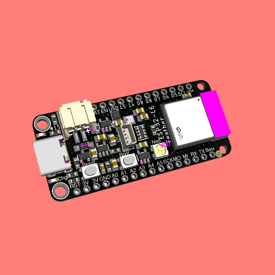
Coming soon - This ESP32-C6 feather is a Matter of fact
ESP32-C6 (https://www.adafruit.com/product/5672) is Espressif’s first Wi-Fi 6 SoC integrating 2.4 GHz Wi-Fi 6, Bluetooth 5 (LE) and the 802.15.4 protocol. It brings the goodness you know from the low-cost C3 series (https://www.adafruit.com/product/5337) and improves it with Zigbee/802.15.4 at 2.4Ghz. That means it could make for great Matter (https://csa-iot.org/all-solutions/matter/) development hardware!
We took our Feather ESP32-S2 (https://www.adafruit.com/product/5000) and swapped out the 'S2 for a C6. Plus some re-routing and here's what we've got: a C6 Feather with lots of GPIO, lipoly charging and monitoring with the MAX17048, (https://www.adafruit.com/product/5580) NeoPixel, I2C Stemma QT port, and a second low-quiescent LDO for disabling the I2C and NeoPixel when we want ultra-low power usage. We also tossed a BME280 (https://www.adafruit.com/product/2652) on there, so you could use it immediately as a low power temp/hum/pressure sensor.
#esp32-c6#wifi-6#bluetooth-5#zigbee#matter-protocol#feather-board#gpio#lipoly-charging#i2c-stemma-qt#bme280-sensor
4 notes
·
View notes
Text
ROBO PICO von Cytron Technologies: Perfekt für deine Roboterideen

In diesem Beitrag möchte ich dir den ROBO PICO von der Firma Cytron Technologies vorstellen und aufzeigen, wie dieser dir bei deinen Roboterideen behilflich sein kann.

Disclaimer: Dieser Beitrag wurde in Zusammenarbeit mit Cytron Technologies erstellt, und ich habe das Produkt ROBO PICO sowie den Raspberry Pi Pico WH kostenfrei erhalten. Die Meinungen und Ansichten in diesem Beitrag sind jedoch meine eigenen und wurden nicht von Cytron Technologies beeinflusst. Ich empfehle nur Produkte und Dienstleistungen, von denen ich überzeugt bin und die für meine Leser von Interesse sein könnten. Den Raspberry Pi Pico WH habe ich dir bereits in einigen Beiträgen auf meinem Blog vorgestellt: - Raspberry Pi Pico W – programmieren einer Wetterstation mit ChatGPT - Raspberry Pi Pico: Programmierung und Entwicklung mit der Arduino IDE auf Linux - Raspberry Pi Pico BASIC #1 – Überblick


Aufbau des ROBO PICO von Cytron Technologies
Die Platine des ROBO PICO verfügt über diverse Schnittstellen an welche die Motoren sowie Sensoren & Aktoren angeschlossen werden können. Hier findest du die derzeit sehr weit verbreiteten Grove Schnittstellen, welche den Vorteil bieten, dass die zum einen nur in eine Richtung gewaltfrei eingesteckt werden können und zum anderen eine fehlerhafte Verkabelung minimiert wird. Du musst hier lediglich drauf achten, dass du einen analogen Sensor auch an analoge Pins anschließt.

Schnittstellen und Klemmen - sieben Grove Schnittstellen, - zwei Schraubklemmen für Motoren, - eine Schraubklemme für eine externe Stromversorgung (3.6V bis 6V), - eine 4 x 3fach Stiftleiste für Servomotoren, - einen Maker Port, kompatibel mit QWIIC, Stemma QT Module (I2C) An den Schraubklemmen für die Motoren findest du jeweils auch Taster um diese auch ohne Code auf dem Raspberry Pi Pico zu testen. Zusätzliche Features - zwei NeoPixel, - zwei frei programmierbare Taster, - einen Piezo Buzzer, - ein Anschluss für eine LiPo Batterie (inkl. laden) mit LED Anzeige,
Lieferumfang zum ROBO PICO
Zum Lieferumfang des ROBO PICO gehört neben der Platine noch eine kleine Tüte mit Anschlusskabel und für die Schraubklemmen ein passender Schraubendreher.

Bezugsquellen
Wenn du dir diese nützliche Platine für deine Roboterideen zulegen möchtest, dann bekommst du dieses entweder im Onlineshop von Cytron Technologies für derzeit 14,9 $ (ca. 13,98 €, stand 14.09.2023) zzgl. Versandkosten. Etwas günstiger bekommst du diesen im Raspishop für derzeit 13,98 € zzgl. Versandkosten.
Aufbauen und programmieren des Hungry Robot mit dem ROBO PICO und Raspberry Pi Pico
Auf der Seite https://www.cytron.io/p-robo-pico findest du einige lustige Projekte zum Nachbauen. Hier habe ich mir den Hungry Robot ausgesucht, der klingt recht lustig. https://youtu.be/zFmcF2K_FcY Zum Aufbau des Hungry Robot benötigst du einen 3D-Drucker. In meinem Fall nutze ich einen Anycubic Pro Mega und das Drucken aller Teile hat dabei 22h Stunden in normaler Qualität gedauert.


Auf Thingiverse bekommst du die benötigten Dateien kostenfrei zum Download: - REKA:BIT Hungry Robot, - Maker Pi RP2040 to REKA:BIT Mounting Holes Ansonsten benötigst du zum Zusammenbauen noch: - sechs 3,0 x 12 mm Schrauben, - vier 3,5 x 12 mm Schrauben, - einen Servomotor Typ SG90, - einen Ultraschallabstandssensor Typ HC-SR04, sowie - kleine Kabelbinder Die Schrauben wähle ich von der Firma Spax und habe ich aus dem örtlichen Toom Baumarkt erworben. Sicherlich sind diese deutlich teurer als die günstigen Noname Schrauben. Jedoch haben die Schrauben von Spax ein scharfes Gewinde, welches besonders für 3D gedruckte Teile super funktionieren und nichts kaputt machen. Zusätzlich benötigst du noch etwas Werkzeug: - einen mittleren Kreuzschraubendreher, - einen kleinen Krezuschraubendreher, - einen kleinen Seitenschneider, - ein Cuttermesser, sowie - einen Satz kleine Schlüsselfeilen Das Cuttermesser sowie die Schlüsselfeilen benötigen wir für die gedruckten Teile. In meinem Fall musste ich das Supportmaterial mit dem Cuttermesser herausbrechen und mit den Feilen ein paar Überstände abfeilen. Hinweis - Verbindungen mit Kabelbinder Die meisten Verbindungen an diesem Roboter werden mit zwei Kabelbinder gelöst. Diese Art eine Verbindung aufzubauen ist wirklich cool und reicht für solche Verbindungen locker aus. https://youtu.be/Ra7Eipm9mgo Du darfst diese jedoch nicht zu stramm anziehen, da diese sich noch etwas bewegen müssen! Schritt 1 - verbinden des ROBO PICO mit dem Gehäuse Verbinden wir zunächst die Platine des ROBO PICO mit der Mounting Plate, dazu nutzen wir vier Schrauben 3,0 x 12 mm. Um diese Platte wiederum mit dem Gehäuse zu verbinden, nutzen wir die vier 3,5 x 12 mm Schrauben.


Schritt 2 - Servomotor einsetzen Der Servomotor wird rechts in die große Öffnung gesteckt, sodass die Aufnahme des Ruderhorns nach oben zeigt und wird ebenso mit zwei Schrauben 3,0 x 12 mm montiert. An diesen Servomotor wird die Schaufel und diese wiederum die Verbindung zum Kopf montiert.


Für die Montage des Ruderhorns benötigst du zwei Schrauben, welche beim Servomotor beiliegen. Den Servomotor verbinde ich am Ende mit dem GPIO12 (unten rechts). Schritt 3 - Montage des Ultraschallabstandssensors Ich habe dir oben in der Liste der benötigten Bauteile auch einen Ultraschallabstandssensor mit Grove Schnittstelle verlinkt. Es gibt auf dem Markt auch welche mit einfacher Stiftleiste, jedoch passen diese nicht in das Loch. (Der Abstand zwischen Sender & Empfänger ist zu weit.)

Ein weiterer Vorteil ist beim Modell mit der Grove Schnittstelle die einfache Verkabelung mit einem vorkonfektioniertem Kabel, welches eine fehlerhafte Verkabelung quasi schon fast ausschließt.


Das Grove Kabel führe ich durch das Loch vom Servomotor und schließe dieses an den GPIO3 an. Schritt 4 - Montage der Schaufel Die Schaufel wird links mit einem Kabelbinder verbunden und rechts an den Servomotor mit zwei Schrauben über ein Ruderhorn angeschraubt.


Das Ruderhorn ist jetzt noch nicht final mit dem Servomotor festgeschraubt, da wir unsere Schaufel mit Pythoncode noch ausrichten müssen. Schritt 5 - Montage des Kopfes und der Verbindung zur Schaufel Der Kopf wird wiederum mit einem Kabelbinder mit dem Körper verbunden und über den Link mit der Schaufel verbunden.


Mit diesem letzten Schritt haben wir nun den Hungry Robot fertig aufgebaut, nun können wir mit der Programmierung beginnen. Programmieren des Hungry Robot in Micropython Den hier verwendeten Raspberry Pi Pico WH kannst du in Circuitpython oder Micropython programmieren und natürlich auch in der Arduino IDE. Nachfolgend zeige ich dir, wie du diesen in Micropython in der Thonny IDE programmierst. Die Thonny IDE kannst du dir kostenfrei unter https://thonny.org/ für Window, macOS und Linux herunterladen. Ggf. musst du deinen Pi Pico noch für Micropython flashen, wie du das machst, habe ich dir im Beitrag Raspberry PI Pico #1 – Vorstellung ausführlich erläutert. Schritt 1 - Programmieren des Servomotors und Ausrichten der Schaufel Im ersten Schritt wollen wir jetzt die Schaufel ausrichten, dazu müssen wir zunächst den Servomotor in die Position 0° bringen. Ich empfehle dir hier den Hungry Robot auf etwas zu stellen, sodass sich ggf. die Schaufel auch ohne Kraft nach unten bewegen kann. # Bibliotheken laden from machine import Pin, PWM from time import sleep #Servomotor am GPIO12 angeschlossen servoPin = 12 #konfigurieren der PWM Kanäle für den Servomotor pwm = PWM(Pin(servoPin)) #der Servomotor Typ SG90 arbeitet mit 50Hz pwm.freq(50) #ermittelte Positionen für die Schaufel valUnten = 1580000 valOben = 500000 #Konstante für die Pause zwischen den Aktionen PAUSE = 2 #Funktion zum öffnen des Mundes def oeffneMund(): global valOben print("oeffneMund") pwm.duty_ns(valOben) sleep(PAUSE) #Funktion zum öffnen des Mundes def schliesseMund(): global valUnten print("schliesseMund") pwm.duty_ns(valUnten) sleep(PAUSE) #Funktion zum deinitialisieren der PWM Kanäle def ende(): pwm.deinit() #Damit das Programm sauber über das STOPP Symbol aus der Toolbar #beendet werden kann und die Funktion ende ausgeführt wird, #bauen wir um die Schleife ein Try/Except try: #initial soll der Mund geschlossen sein schliesseMund() #Schleife von 1..5 for i in range(1,5): #Mund öffnen oeffneMund() #Mund schließen schliesseMund() #Programm beenden ende() #Wenn ein Fehler aufgetreten ist, dann.... except: print("Programm beendet!") ende() Schritt 2 - Erkennen eines Signals vom Ultraschallabstandssensors Im nächsten Schritt müssen wir jetzt ein Signal vom Ultraschallabstandssensor empfangen und auswerten. Die Funktionsweise des Hungry Robot ist ja, dass wir einen kleinen Gegenstand auf die Schaufel legen und dann dieser Gegenstand im Körper des Robots mithilfe eben dieser Schaufel befördert wird. Dazu nehmen wir den Abstand des Ultraschallabstandssensors und reagieren, wenn dieser kleiner als 8 cm ist.

Wie du einen Ultraschallabstandssensor in Micropython programmierst habe ich dir bereits im Beitrag Programmieren mit MicroPython #8: Ultraschall Abstandssensor HC-SR04 am ESP32 betreiben am ESP32 erläutert, dieses funktioniert auch fast 1:1 mit dem Raspberry Pi Pico WH. Der hier verwendete Ultraschallabstandssensor von Seeed Studio hat nur einen digitalen Pin. Wir müssen also im Code jeweils immer umschalten. ##Import der benötigten Bibliotheken import machine from utime import sleep_us, ticks_us from time import sleep #Starten der Endlosschleife while True: #definieren das der Pin als Ausgang dient pin=machine.Pin(3, machine.Pin.OUT) #Pin aktivieren pin.on() #zwei Microsekunden warten sleep_us(2) #Pin deaktivieren pin.off() #zehn Microsekunden warten sleep_us(10) #Pin aktivieren pin.on() #definieren das der Pin als Eingang pin=machine.Pin(3, machine.Pin.IN) #Endlosschleife solange der Pin LOW/0 ist while pin.value() == 0: pass #zwischenspeichern der vergangenen Microsekunden ticks1 = ticks_us() #Endlosschleife solange der Pin HIGH/1 ist while pin.value() == 1: pass #zwischenspeichern der vergangenen Microsekunden ticks2 = ticks_us() #die differenz zwischen den beiden Werten geteilt durch 58 sind #die Zentimer zum Objekt cm = (ticks2 - ticks1) / 58.0 #Ausgeben des berechenenten Wertes print(cm, " cm") #einlegen einer Pause von 0.5 Sekunden sleep(0.5) Wenn wir uns nun die Werte anschauen, dann sehen wir, dass der Ultraschallabstandssensor die vordere Spitze der Schaufel erfasst, somit haben wir den maximalen Abstand ermittelt und müssen später nur prüfen, ob dieser um x Zentimeter unterschritten wurde.

Zusammenfassen der Codes Nun haben wir beide Codefragmente fertiggestellt und können diese zu einem zusammenfassen. Zusätzlich habe ich hier noch eine kleine Funktion eingebaut, sodass eine Tonfolge auf dem Piezo Buzzer wiedergeben wird, wenn eine Aktion ausgeführt werden soll. ##Import der benötigten Bibliotheken from utime import sleep_us, ticks_us from machine import Pin, PWM from time import sleep #Servomotor am GPIO12 angeschlossen servoPin = 12 #konfigurieren der PWM Kanäle für den Servomotor pwm = PWM(Pin(servoPin)) #der Servomotor Typ SG90 arbeitet mit 50Hz pwm.freq(50) #ermittelte Positionen für die Schaufel valUnten = 1580000 valOben = 500000 buzzer = PWM(Pin(22)) def makeBeep(): buzzer.freq(350) buzzer.duty_u16(1000) sleep(0.1) buzzer.duty_u16(0) sleep(0.1) buzzer.freq(750) buzzer.duty_u16(1000) sleep(0.1) buzzer.duty_u16(0) sleep(0.1) buzzer.freq(350) buzzer.duty_u16(1000) sleep(0.1) buzzer.duty_u16(0) sleep(0.1) def readUltrasonicSensor(): #definieren das der Pin als Ausgang dient pin=machine.Pin(3, machine.Pin.OUT) #Pin aktivieren pin.on() #zwei Microsekunden warten sleep_us(2) #Pin deaktivieren pin.off() #zeh Read the full article
0 notes
Link

via Adafruit Industries – Makers, hackers, artists, designers and engineers! https://ift.tt/2Q48ozS
0 notes
Text

Coming soon - Stemma QT breadboard pal takes a load off I2C wiring
we got a request for a little I2C breadboarding helper - something that will let people add stemma QT / qwiic connectors (https://www.adafruit.com/stemma) to a project easily. instead of just an SMT-to-THM adapter we also tossed on a 10uF power decoupling cap, power LED (that can be disabled) and 10K I2C pullup resistors (that also can be disabled). we sketched this one out pretty fast but like how it turned out! we may also make this board available with headers pre-soldered since stemma QT is specifically designed for solder-free work.
7 notes
·
View notes
Text

Fruit Jam RP2350B credit-card mini computer with all the fixin's 🍓🍇💾
We were catching up on a recent Hackaday hackchat with Eben Upton (https://hackaday.io/event/202122-raspberry-pi-hack-chat-with-eben-upton) and learned some fun facts: such as the DVI hack for the RP2040 was inspired by a device called the IchigoJam (https://www.hackster.io/news/ichigojam-combines-strawberry-and-raspberry-to-deliver-a-raspberry-pi-pico-powered-educational-micro-66aa5d2f6eec). We remember reading about this back when it was an LPC1114, now it uses an RP2040. Well, we're wrapping up the Metro RP2350 (https://www.adafruit.com/product/6003), and lately, we've been joking around that with DVI output and USB Host support via bit-banged PIO, you could sorta build a little stand-alone computer. Well, one pear-green-tea-fueled-afternoon later we tried our hand at designing a 'credit card sized' computer - that's 3.375" x 2.125", about the same size as a business card (https://hackaday.com/2024/05/07/the-2024-business-card-challenge-starts-now/) and turns out there's even a standard named for it: ISO/IEC 7810 ID-1 (https://www.iso.org/standard/70483.html).
Anyhow, with the extra pins of the QFN-80 RP2350B, we're able to jam a ridonkulous amount of hardware into this shape: RP2350B dual 150MHz Cortex M33 w/ PicoProbe debug port, 16 MB Flash + 8 MB PSRAM, USB type C for bootloading/USB client, Micro SD card with SPI or SDIO, DVI output on the HSTX port, I2S stereo headphone + mono speaker via the TLV320DAC3100 (https://www.digikey.com/en/products/detail/texas-instruments/tlv320dac3100irhbt/2353656), 2-port USB type A hub for both keyboard and mouse or game controllers, chunky on-off switch, Stemma QT I2C + Stemma classic JST 3-pin, EYESPI for TFT displays, 5x NeoPixels, 3x tactile switches, and a 16-pin socket header with 10 A/D GPIO + 5V/3V/GND power pins. The PSRAM will help when we want to do things like run emulations that we need to store in fast RAM access, and it will also let us use the main SRAM as the DVI video buffer.
When we get the PCBs back and assembled, what should we try running on this hardware? We're pretty sure it can run DOOM. Should that be first? :) We also need a name. Right now, we're just calling it Fruit Jam since it's inspired by the IchigoJam project.
#fruitjam#rp2350b#raspberrypi#microcomputer#hackaday#diyelectronics#retrocomputing#creditcardpc#hardwarehacking#usbhost#dvioutput#psram#retrogaming#makercommunity#opensourcehardware#homemadecomputer#minipc#embeddeddevelopment#techinnovation#electronicsproject#tinkering#cortexm33#doomport#custompcb#hacktheplanet#hardwaredesign#diytech#retroconsole#handheldgaming#fruitjampc
34 notes
·
View notes
Text

Triple Matrix Bonnet Makes Big Bright Displays 🔴🟢🔵✨
With our latest work on getting HUB75 RGB matrices working on the Raspberry Pi 5
we can now create stunning LED displays. But what if we want more pixels? At some point, we max out the bandwidth of the RP1 chip, but we can still squeeze out additional performance by updating the PIO commands to output two or three matrix strings instead of just one.
Thus, the Triple Output RGB Matrix Bonnet you see here! We're using the classic Active-3 pinout
with a switch to select whether the 4th or 8th pin is connected to address E.
Since we expect large matrix grids drawing 10A+ of current, there's no onboard power management—the 5V supply should be connected separately through thick power wires. This board is for data only. If you aren't using port 3, the I2C remains available, so we've added a Stemma QT port for extra flexibility.
#leddisplay#raspberrypi5#rgbmatrix#adafruit#electronics#maker#tech#opensource#diy#hardware#innovation#lighting#embedded#creativecoding#coding#raspberrypi#matrixdisplay#ledmatrix#iot#hardwarehacking#piomatter#blinka#stemmaqt#hackerspace#engineering#prototyping#techgadgets#electronicprojects#powerfuldisplays#makersmovement
47 notes
·
View notes
Text

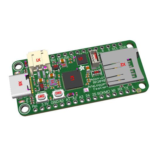
First of the Bones Rises – RP2350 Adalogger 🦴
With the RP2350 chip in wide distribution , we're now able to come up with a lot of variants of our popular RP2040 "Bones"
https://blog.adafruit.com/2023/01/22/rp2040-feather-bones-for-a-few-different-varieties/
that ended up becoming a dozen different boards.
We're starting with the 'Adalogger' design folks love: with a microSD card socket that is wired for SPI or SDIO. A separate regulator allows the I2C/uSD to be powered off completely for ultra-low power usage. This didn't make as much sense for the RP2040 because it was not a particularly low-power chip. There's also a Stemma QT port for plugging in external sensors.
What other "Bones" should we spin up?
#rp2350#adalogger#raspberrypi#microcontroller#lowpower#devboard#stemmaqt#makerlife#electronicsprojects#openhardware#embeddeddev#hardwarehacking#iotdevelopment#datalogger#microsd#sdio#spi#i2c#engineering#programming#linux#python#java#software engineering#coding#regulators#featherbones#techinnovation#diytech#circuitdesign
15 notes
·
View notes
Text

Trying to design a great WLED board 🌈🦄🦃
While waiting for the turkey to finish brining, we're designing a board for using WLED - and we want to make like the bestest board in the whole world.
Our resident mermaid, firepixie
, makes a lot of projects with WLED, and she loves it! So, how can we make something that will be powerful but not too bulky? Here are some things we're thinking about as the design starts to congeal like cranberry sauce:
Power via USB Type C PD with a slide switch that selects between 5, 12, and 20V (24V pixels can usually run fine at 20V) OR via a 2.1mm DC jack. With ideal diodes, it's good for up to 5A from either.
ESP32-Mini module with built-in or optional wFL antenna port. The classic '32 has broad support, even if we'd prefer the 'S2 or 'S3.
There are three output signal terminal block sets, with power and ground for each. They'll be level-shifted to 5V.
Built in I2S microphone (we're still pondering this one).
Stemma QT I2C port to connect external sensors/OLEDs/etc.; separate analog/digital input JST port.
1.3"x1.75" / 33mm x 45mm size with mounting holes.
Anything we're missing, anything that's extraneous?
#electronics#wled#makerspace#esp32#usbtypec#diyprojects#arduino#adafruit#ledlights#hardwaredesign#microcontroller#iot#esp32mini#stemmaqt#circuithacks#ledart#makersgonnamake#powerdesign#tinytech#firepixie
22 notes
·
View notes
Text
A Compact Pi Compute Module Backpack 🍓🥧📸🎒
We used to stock a PiCam Module
that would plug into a Pi CM4 or CM5 - recently we went to restock it, but the vendor hasn't replied to our emails for many months. So, it could be a good time for us to design something that works similarly but with more capabilities. So we tasked Timon
with designing something for us - we just said, "Make the best thing ya can," and he delivered! Check this board out that plugs onto the compute module and provides many great accessories: USB connection for bootloading/USB gadget, USB 3.0 host type A for CM5, micro HDMI, micro SD card for data storage on 'Lite modules, camera connection, and mount, two DSI connectors, fan connect, Stemma QT / Qwiic connection, and RTC battery. There's one shutdown button for CM5 and two GPIO buttons plus one LED. Timon's gonna try to add an EYESPI connector for our next rendering so we can get some I2C/SPI/PWM outputs easily. What do you think? We wanted to keep it compact and not too pricey (aiming for <$30 cost. We'll see if we can get it there) but were able to craft fairly complex projects in a small space.
#raspberrypi#computeModule#electronics#maker#hardware#embedded#engineering#diy#tech#innovation#pcbdesign#usb3#microsd#hdmi#camera#stemmaqt#qwiic#gpio#fan#rtc#devboard#prototyping#opensource#electronicsdesign#robotics#automation#coding#hobbyelectronics#hackerspace#geekstuff
17 notes
·
View notes
Text

The SC16IS74x is an I2C to UART converter
If you know us, you know we luuuuuv I2C as a near-universal interface for sensors, GPIO expanders, OLEDs, and other various devices under our Stemma QT family: https://www.adafruit.com/search?q=stemma+qt 🌱. But we still bump into some UART devices: https://www.adafruit.com/search?q=uart here and there—GNSS/GPS units, MP3 playback chips, fingerprint sensors, LIDARs, and more.
These can be annoying if you only have one UART port-or none at all! So we put together this SC16IS74x breakout. It can use either the SC16IS740: https://www.digikey.com/en/products/detail/nxp-usa-inc/SC16IS740IPW-128/1301043 or SC16IS741: https://www.digikey.com/en/products/detail/nxp-usa-inc/SC16IS741AIPWJ/4486521 chips-both essentially the same for our purpose: providing a bidirectional UART with flow control. Address jumpers on the back allow you to select up to four devices on one I2C bus—and there's even native Linux kernel drivers: https://www.kernel.org/doc/Documentation/devicetree/bindings/serial/nxp%2Csc16is7xx.txt 🧠.
7 notes
·
View notes
Text

Got lots and lots of solenoids?
We were chatting with a customer and realized we need a better solution for customers with many solenoids or other high-current on/off loads. This breakout will make it easy to control and power many inductive or high-current loads. An mcp23017
https://www.digikey.com/short/nf4pn2rc
expander over I2C provides 8 output pins, each connected to an AO3406 N-Channel FET
https://www.digikey.com/short/rh398zbh
with a 1N4007 flyback diode.
https://www.digikey.com/short/343h9890
Terminal blocks allow for quick wiring to power and each high current output, including one chunky block for the power input. The other 8 expander I/Os are exposed if you want buttons or simple LEDs. The breakouts have stemma QT for fast chaining/control over I2C.
#solenoids#electronicsprojects#highcurrent#i2c#mcp23017#nchannelfet#diycircuits#engineeringtools#hardwarehacking#inductiveloads#flybackdiode#terminalblocks#powersolutions#makerspace#hardwaredesign#circuitboard#stemmaqt#microcontrollers#electronicsengineering#techtools#diyengineering#embeddeddesign#electroniccomponents#breakoutboard#electronicsdiy#hardwareprojects#loadcontrol#electronicsgeek#techinnovation#powercontrol
14 notes
·
View notes
Text
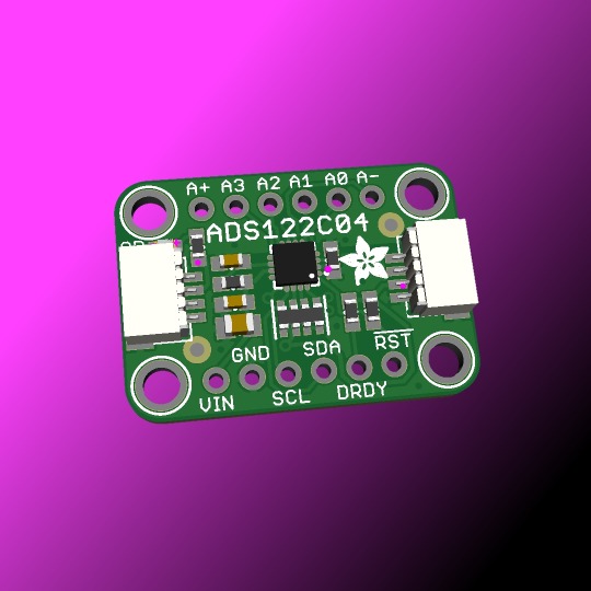
We stock and use a couple of different I2C ADCs, such as the NAU7802
and the HX711
Both of these are kinda designed specifically for load cells. This is a more general-purpose 24-bit ADC using the ADS122C04
with adjustable 1x to 128x gain, up to 2ksps and an internal reference. It can be single or differential input. Good for sensitive things like RTDs, thermocouples, or resistive bridges like load cells! Coming soon.
#adafruit#ADS112C04#24bit#4channel#i2c#adc#NAU7802#loadcells#ti#texasinstruments#rtd#thermocouples#24bitadc#analogtodigital#electronicsdesign#sensormeasurement#embeddedhardware#differentialinput#internalreference#gaincontrol#highresolution#texasinstrumentsadc#sensorinterface#loadcellapplications#precisionelectronics#thermocouplesupport#rtddesign#adcdesign#i2cinterface#resistivebridges
12 notes
·
View notes
Text
Coming soon - RP2040 "Bones" AdaLogger
We decided to take a look back at our RP2040 "Bones" boards, and found that we somehow neglected to make one for SD card interfacing. so here it is! with a micro SD socket, we connect all the SPI/SDIO pins so either interface can be used. We still have space for all the classic "Bones" elements: RP2040 with 8 MB Flash, USB C, battery charging, neopixel and Stemma QT I2C port.
22 notes
·
View notes
Text

A new, upgraded style of soil sensor 🪴💧🌡️
For a while, we've had a SAMD09-based soil sensor (https://www.adafruit.com/product/4026) that uses the built-in capacitive sensing. It works well but has some non-linearity in its response to wet soil. We wanted to try a different system of measuring capacitance and update it to a 3~5V friendly ATtiny816 (https://www.adafruit.com/product/5681), which lets us ditch the regulator and shifting circuitry. We'll also Stemma QT-ify it and add a NeoPixel and an AHT20 low-cost temperature/humidity sensor (https://www.adafruit.com/product/4566) for an 'all in one' gardening sensor. The un-rendered part in the center is a 3-pin DIP switch in 1.27mm pitch, for easily setting the I2C address. Coming soon.
#adafruit#soilsensor#plants#gardentools#smarthome#gardeningtech#plantsensor#sensorupgrade#diygarden#plantcare#techinnovation#smartsensor#homeautomation
15 notes
·
View notes
Text

A mini GPS from uBlox with I2C and UART 🛰️📡🔧
The SAM-M8Q
is an entry-level 'all in one' GPS from uBlox - it comes with both UART and I2C interfaces plus a built-in antenna so it's ready to go 'out of the box.' It's also fairly small, so we decided to try and make a little breakout for it. It exposes both interfaces, but we expect most folks will like using the Stemma QT port for instant I2C interfacing. We gotta dig into uBlox's interface since we expect the I2C to be a little more complex than the PA1010 we've used.
#adafruit#gps#ublox#i2c#uart#sam-m8q#stemma#pa1010#electronics#gpsmodule#makerspace#hardwaredesign#embedded#opensourcetools#diyprojects#techinnovation#electronicsprojects#gpsbreakout#prototyping#smalldevices#sensorintegration#microcontroller#makersmovement
7 notes
·
View notes
Text

BU9796 prototype finally comes to light ✨🔧🖥️
We covered the BU9796 a loooooooooong time ago on the Great Search while looking for an I2C LCD segment driver ...
youtube
but sadly, we never got around to making that breakout board. Til' now! This one features the FS series of the chip, which has some more segments: in this board, we expose 4 common and 18 segments to keep the board from getting too big. This chip runs at 3V or 5V, so it should be easy to use with any device. We still need to figure out what VLCD connects to - some parts of the datasheet say VDD, and some say VSS, so we left a jumper on the back. That way, we can connect it correctly when we are more awake. Stemma QT makes this a plug-and-play driver for just about any micro! Coming soon…
#adafruit#BU9796#prototype#i2c#lcd#hardwaredesign#electronics#makercommunity#techinnovation#engineering#diyelectronics#newrelease#devboard#microcontrollers#stemmaqt#Youtube
10 notes
·
View notes