#I2C CAN Bus Module
Explore tagged Tumblr posts
Visit Tumblr Blog
Explore Tumblr blogs with no restrictions, modern design and the best experience.
Last Seen Tumblr Blogs


Fun Fact
In February 2021, Tumblr had 518.6 million blog accounts.
Text
https://www.futureelectronics.com/p/semiconductors--comm-products--i2c/pca9515adp-118-nxp-5973557
I2C CAN Bus Module, I2C adapter, I2C devices, Serial Peripheral Interface
PCA9515A Series 3.6 V 5 mA 400 kHz 6 pF Surface Mount I2C-bus Repeater - SOIC-8
#Comm Products I2C#PCA9515ADP#118#NXP#I2C CAN Bus Module#I2C adapter#I2C devices#Serial Peripheral Interface#I2C Level Converter#i2c protocol#spi protocol#uart protocol#i2c communication#i2c protocol in embedded system#I2C-bus Repeater
1 note
·
View note
Text
https://www.futureelectronics.com/p/semiconductors--comm-products--i2c/pca9532pw-118-nxp-5033862
16-bit I2C-bus LED Dimmer, Embedded communication, image processing,
PCA9532 Series 5.5 V 350 uA 400kHz SMT 16-bit I2C-bus LED Dimmer - TSSOP-24
#NXP#PCA9532PW#118#Comm Products#I2C#16-bit I2C-bus LED Dimmer#Embedded communication#image processing#High-Speed#Isolated CAN Transceiver ICs#CAN bus lines#i2c modules#Can Power Systems#CAN transceiver#Ethernet MAC controller
1 note
·
View note
Text
https://www.futureelectronics.com/p/semiconductors--comm-products--i2c/pca9532pw-118-nxp-5033862
I2c bus, Embedded communication, Isolated CAN Transceiver ICs
PCA9532 Series 5.5 V 350 uA 400kHz SMT 16-bit I2C-bus LED Dimmer - TSSOP-24
#NXP#PCA9532PW#118#Comm Products#I2C#Ethernet MAC controller#communication protocol#i2c module#bus#Embedded communication#Isolated CAN Transceiver ICs#High-Speed CAN Transceiver#CAN transceiver#SPI bus#CAN bus lines
1 note
·
View note
Note
WARNING: LONG ASK INCOMING
For hobby electronics there’s two major kinds of processors: Microcomputers and Microcontrollers. Microcomputers are small full computer systems like the Raspberry Pi, they typically run a general-purpose OS (typically some flavor of Linux) and are useful for the kinds of projects that require basically a full computer to function, but not necessarily individual sensors. They’re a great place to start for people who don’t know a whole ton about programming or working with individual components because they typically can output a true GUI to a screen and have the capabilities of a regular desktop computer. They have a main processor, true RAM, and either large on-board storage space or a way to read a storage device, like an SD card.
Microcontrollers are less complicated (component wise) than microcomputers, but as a result are more difficult for total beginners to begin working with. They’re typically primarily a SoC (System on a Chip) processor without discrete RAM modules and a very small EEPROM (on-ship storage space) and need to have components wired and configured to them to be able to do much more than being a fancy calculator. They’re used for when you need something to carry out electronic functions or get sensor readings, but not necessarily a full operating system, so they’re best suited for small/integrated applications. Your helmet uses a microcontroller to control the LEDs you used in the Cunt Machine post.
I build high-power model rockets as a hobby and with my university team, so I work with both kinds of processor as part of designing payload systems. I typically prefer microcontrollers in these as most of what we do doesn’t need an actual OS to run, and they’re smaller/lighter than microcomputers. One of the advantages of a microcontroller is that it runs a Real-Time OS (RTOS) which forgoes all the user-friendliness of things like windows and linux to instead be the bare minimum backend necessary to run code uploaded into the processor.
The main advantage of using a microcontroller is really that they’re typically a lot cheaper than microcomputers are and are plenty powerful for really embedded applications. They also make other parts of whatever system is being built cheaper/easier to integrate because they require less overhead to function - the raspberry pi needs a minimum of 5 volts of power to work, while a chip like an ESP32-PICO can run at 1.8V.
The main way you make sensors/buttons/peripherals work with a microcontroller is via digital communication busses. There’s a few protocols, the most common being I2C, SPI, and UART. I’ll talk about I2C since that’s generally the most common. With I2C each component is assigned a 2-byte “address” that they’re identified by. When the controller sends a request signal on the I2C data bus, every sensor along the line will return their own signal, marked with their address so that they can be identified. It allows for a large number of devices to be put on the same lines and you can daisy-chain them through each other to the microcontroller.
I’ll be honest I really can’t think of a good way to say much more on the subject as like a starting message because I’ve been working with computers so long all the tech stuff for me is second nature, but if you have any questions ask away I can probably answer them or google them.
.
#AAAAAAAAAAAAAAAAAAAA TY INFORMATION#no yeah this is either really beginner friendly or. friendly to how much i have learned so far#tysm!!!! your insight is consistently so helpful <3#ask#lobsterbitches
27 notes
·
View notes
Text
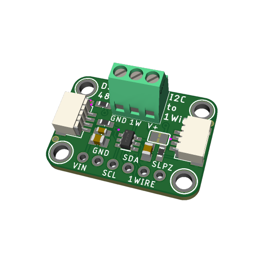
DS2484 I2C to 1-Wire converter
In theory, there's a lot of 1-Wire devices out there, but in reality almost everyone uses 1-Wire for DS18b20 temperature sensors. the long wire lengths and ease of 'chaining' by sharing a single bus wire makes it perfectly fine for this purpose. you can bitbang 1Wire on most microcontrollers, and some SBCs like Raspberry Pi have kernel module support. (https://learn.adafruit.com/adafruits-raspberry-pi-lesson-11-ds18b20-temperature-sensing) But there might be chips without the 1-Wire capability, or maybe you want to use 1-Wire devices on your desktop computer or other SBC with I2C but no 1W.
by special request! this is a DS2484 (https://www.digikey.com/short/5f85v4tf) Stemma QT board that uses the newest I2C-to-1W controller chip, with ESD protection and support for split supplies. you can easily connect it to an existing I2C bus and then use the screw terminals to attach multiple DS18b20's - this library looks promising (https://github.com/pilotak/DS248X) for Arduino. Coming soon!
16 notes
·
View notes
Text
ADXL335 Module
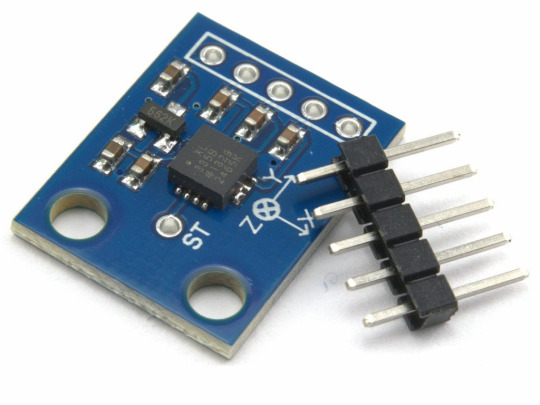
The ADXL335 Module is a compact and energy-efficient 3-axis accelerometer that provides signal conditioned voltage outputs. ADXL335 Module has a minimum full-scale range of ±3 g for accurately measuring acceleration.
This breakout board has the capability to measure both static gravity acceleration in tilt-sensing scenarios, as well as dynamic acceleration caused by movement, impact, or tremors. It is equipped with a built-in voltage regulator and operates seamlessly at 3.3V and 5V (3-5V).
An accelerometer is an electro-mechanical device capable of measuring both static and dynamic acceleration forces. This includes the constant force of gravity acting on your feet, as well as any movement or vibrations that may affect the device.
Systems such as FPV, RC, and Robots.
Navigation systems that utilize GPS technology
Acknowledging and recording the effects.
Devices used for gaming and virtual reality experiences
Features that are activated by movement.
Efficient energy conservation for portable devices.
Monitoring and compensating for vibrations
The detection of free-fall.
Detecting 6D orientation
The characteristics include:
One feature on the board is a Low Dropout (LDO) Voltage Regulator.
Can be connected to either a 3V3 or 5V Microcontroller.
With an ultra-low power consumption rate of only 40uA in measurement mode and an impressive 0.1uA in standby at 2.5V, this device ensures efficiency without compromising on performance.
This feature includes the ability to detect taps and double taps.
A feature for detecting free-fall is included.
The analog output has been successfully connected to the device and is now functioning properly.
Incorporate an ultra low noise linear LDO voltage regulator.
The device contains built-in onboard filters that effectively minimize noise from the motor and other high current electronics.
All sensors on the I2C bus
By using a soldered jumper, it is simple to choose two I2C addresses for the MPU6050.
The LED indicating power.
Incorporate a Logic level converter for I2C connectivity.
Optimized for 5V logic
1 note
·
View note
Text
Explain the concept of bus protocols in embedded systems.
Bus protocols are standardised ways for various embedded system components or devices to communicate with one another in embedded systems. A bus is a means of communication that enables the transfer of data and control signals between various modules, including peripherals, memory devices, and microcontrollers. Bus protocols provide out the guidelines and norms for addressing, synchronisation, and data transfer, providing seamless interoperability.
I2C (Inter-Integrated Circuit), a bus protocol that is often used, has a master-slave design for communication. It enables numerous devices with separate addresses to be connected to the same bus. Connecting sensors, EEPROMs, and other low-speed peripherals is frequently done via the I2C protocol.
Bus protocols are essential for enabling communication between the many embedded systems and components in electric vehicles (EVs). Between vital components like the Electric Control Unit (ECU), motor controllers, and other subsystems, these protocols enable flawless data transmission and control signals. The Controller Area Network (CAN), which is renowned for its dependability and capacity to enable real-time communication, is one bus protocol that is frequently used in EVs. CAN makes it easier for different ECUs to work together and ensures precise control over things like the motor, battery, and charging systems.
SPI (Serial Peripheral Interface), which uses a master-slave setup with several slaves, is another widely used protocol. SPI is frequently used to interface with gadgets like flash memory, sensors, and display controllers because of its high-speed data transfer capabilities.A popular and easy-to-use serial communication protocol is the Universal Asynchronous Receiver/Transmitter (UART), which is frequently used for point-to-point communication between devices.
A reliable bus protocol that is used frequently in automotive and industrial applications is called CAN (Controller Area Network). It enables real-time data interchange by supporting connection between electronic control units (ECUs) in automobiles or in automotive embedded .Bus protocols, which lay out the guidelines for effective and dependable communication between various components, are essential in embedded systems. The selection of a particular protocol is influenced by variables like data transfer rate and distance.
0 notes
Text
Schneller, stärker, drahtloser: Der Vergleich von Arduino UNO R4 WiFi und R3

Willkommen zu meinem umfassenden Überblick über den brandneuen Arduino UNO R4 WiFi! In diesem Beitrag werfen wir einen detaillierten Blick auf diesen leistungsstarken Mikrocontroller und vergleichen ihn mit seinem betagten Vorgänger, dem Arduino UNO R3 aus dem Jahr 2003. Ich werde dir nicht nur alles über die spannenden Features des Arduino UNO R4 WiFi erzählen, sondern zeige dir auch praktische Beispiele zur Programmierung des verbauten ESP32 Chips und der beeindruckenden 12x8 LED Matrix in der Arduino IDE. Tauche mit mir ein in die Welt der modernen Mikrocontroller und entdecke, wie der Arduino UNO R4 WiFi deine Projekte auf ein ganz neues Level bringen kann. Los geht's!


Arduino UNO R3

Arduino UNO R4 WiFi
Überblick über den Arduino UNO R3
Kommen wir zunächst zum betagten Arduino UNO R3, welcher im Jahr 2003 veröffentlicht wurde. Die erste Version des Arduino UNO kam sogar zunächst mit einer 9poligen RS232 Schnittstelle daher. Um den Arduino UNO R3 hat sich eine große und wie ich finde großartige Community gebildet, welche coole Projekte, Sensoren, Aktoren und Shields erstellt haben. Mit den Jahren kamen dann noch weitere Mikrocontroller dazu wie der Arduino Nano, Leonardo, Micro etc.
Vorstellung des Arduino UNO R4 WiFi
Tauche ein in die faszinierende Welt des Arduino UNO R4 WiFi! Dieser neue Mikrocontroller bewahrt den beliebten UNO Formfaktor und 5 V Betriebsspannung des Vorgängers, UNO R3. Doch der R4 WiFi bietet noch viel mehr!


Mit erweiterter Speicherkapazität und schnellerem Taktsignal ermöglicht er präzisere Berechnungen und die mühelose Umsetzung komplexer Projekte. Du wirst begeistert sein von der verbesserten Leistungsfähigkeit, die dir neue Möglichkeiten eröffnet. Zudem führt der R4 WiFi neue Onboard-Peripheriegeräte wie einen 12-Bit DAC, CAN-Bus und Operationsverstärker ein, die erweiterte Funktionen und Gestaltungsmöglichkeiten bieten. Jetzt kannst du noch anspruchsvollere Projekte realisieren und deine Kreativität voll ausleben. Mit seiner WLAN- und Bluetooth-Unterstützung durch das ESP32-S3-Modul ermöglicht er drahtlose Konnektivität für deine Projekte. Du kannst deine Ideen problemlos vernetzen und drahtlos steuern. Und das ist noch nicht alles! Der R4 WiFi verfügt über eine Qwiic I2C-Schnittstelle für einfache Verbindungen zu Komponenten aus dem Qwiic-Ökosystem. Mit nur wenigen Handgriffen kannst du eine Vielzahl von Sensoren und Aktoren in deine Projekte integrieren. Du kannst den R4 WiFi sogar mit einer LED-Matrix für Animationen oder zur Visualisierung von Sensordaten nutzen. Die leuchtstarke 12x8-Matrix ermöglicht dir eindrucksvolle visuelle Effekte und spart dir zusätzliche Hardware.
Vergleich der technischen Spezifikationen
In der folgenden Tabelle findest du einen detaillierten Vergleich der technischen Daten zwischen dem Arduino UNO R4 WiFi und dem Arduino UNO R3. Diese Übersicht gibt dir einen klaren Überblick über die Unterschiede und Gemeinsamkeiten der beiden Mikrocontroller.

Von den Mikrocontrollern über die Kommunikationsschnittstellen bis hin zu zusätzlichen Features - diese Tabelle hilft dir dabei, die richtige Wahl für dein Projekt zu treffen. Schau dir die Daten genau an und entdecke, welcher Mikrocontroller am besten zu deinen Anforderungen passt. Technische DatenArduino UNO R4 WiFiArduino UNO R3MikrocontrollerRenesas RA4M1 (Arm Cortex-M4)Microchip ATmega328PUSBUSB-Typ-CUSB-Typ-Bdigitale I/O Pins1414analoge Eingänge66DAC1-PWM Pins66SchnittstellenUART (1x), I2C (1x), SPI (1x), CAN (1x)UART (1x), I2C (1x), SPI (1x)Spannung am I/O Pin5V5VEingangsspannung (VIN)6-24V6-20VTaktgeschwindigkeit48MHz16MHzFlash Speicher256 KB32 KBRAM32 KB2 KBZusätzliche FeaturesWiFi und Bluetooth-
Leistungsunterschiede: CPU und Speicher
Ein bedeutender Leistungsunterschied zwischen dem Arduino UNO R4 WiFi und dem Arduino UNO R3 liegt in der CPU und dem verfügbaren Speicher. Während der Arduino UNO R3 ein 8-Bit-System mit 2 KB RAM nutzt, setzt der Arduino UNO R4 WiFi auf eine leistungsstarke 32-Bit-CPU und bietet sowohl 256 KB Flash-Speicher als auch 32 KB RAM. Der Arduino UNO R3 mit seinen 16 MHz Taktfrequenz bietet solide Leistung für viele Anwendungen. Allerdings kann der begrenzte Speicher von nur 32 KB zu Herausforderungen führen, da Entwickler ihren Quellcode sorgfältig optimieren müssen, um den verfügbaren Speicher effizient zu nutzen. Der Arduino UNO R4 WiFi hingegen bietet nicht nur den Vorteil einer 32-Bit-CPU für verbesserte Leistung und präzisere Berechnungen, sondern auch einen erweiterten Speicher. Mit 256 KB Flash-Speicher steht mehr Platz für den Quellcode zur Verfügung, was die Umsetzung komplexerer Projekte erleichtert. Zusätzlich bietet der R4 WiFi 32 KB RAM, um größere Datenmengen effizienter zu verarbeiten. Die Kombination aus einer 32-Bit-CPU und einem größeren Speicher im Arduino UNO R4 WiFi eröffnet Entwicklern neue Möglichkeiten zur Realisierung anspruchsvoller Projekte, ohne sich so stark auf die Optimierung des Speicherbedarfs konzentrieren zu müssen. Insgesamt bietet der Mikrocontroller mit seiner 32-Bit-CPU und dem erweiterten Speicher eine deutliche Leistungssteigerung im Vergleich zum Arduino UNO R3. Dies ermöglicht eine effizientere Entwicklung von anspruchsvollen Projekten und eröffnet neue Perspektiven für kreative Ideen.
Drahtlose Konnektivität: WLAN-Funktionen des UNO R4 WiFi
Der Arduino UNO R4 WiFi ist mit einem leistungsstarken ESP32 S3 ausgestattet, der eine Taktfrequenz von bis zu 240 MHz und einen beeindruckenden 512 kB SRAM bietet. Mit dieser Kombination können wir noch mehr Power aus dem Mikrocontroller herausholen und anspruchsvollere Projekte realisieren.

ESP32-S3-MINI-1 Chip vom Arduino UNO R4 WiFi Es gibt zwar bereits Mikrocontroller im UNO-Formfaktor mit einem ESP32, wie z.B. den Keyestudio ESP32 Plus oder den AZ-Delivery ESP32, die ich bereits auf diesem Blog vorgestellt habe. Aber der Arduino UNO R4 WiFi hat seinen eigenen Charme und bietet zusätzliche Features.

Keyestudio ESP32 Plus

AZ-Delivery D1 ESP32 Um die WiFi-Schnittstelle des UNO R4 WiFi zu programmieren, zeige ich dir in einem speziellen Beispiel, welches ich gesondert veröffentlichen werde. Mit der drahtlosen Konnektivität des Arduino UNO R4 WiFi stehen dir unzählige Möglichkeiten offen. Du kannst drahtlos auf Daten zugreifen, Fernsteuerungen realisieren und sogar IoT-Projekte umsetzen.
Anwendungsbeispiele und Projektmöglichkeiten für beide Modelle
Mit der eingebauten WiFi-Schnittstelle bietet der Arduino UNO R4 eine breite Palette an Anwendungsmöglichkeiten. Du kannst einfache Aktoren schalten oder sogar große IoT-Projekte realisieren, die über ein Dashboard in der Arduino Cloud visualisiert werden können. Der Arduino UNO R3 hat sich besonders in der Lehre zur Mikrocontroller-Programmierung bewährt. Auch ich habe bereits einige Schulungen zur Programmierung von Mikrocontrollern durchgeführt und dabei den Arduino UNO R3 (sowie seinen kleinen Bruder, den Arduino Nano V3) eingesetzt. Hier sind einige bereits veröffentlichte Beiträge zu Arduino-Projekten, die ich verfasst habe und die den Arduino UNO R3 vorstellen: - Arduino Grundkurs im Jugendfreizeitzentrum Schöningen - Arduino Workshop #2 2019: OTTO DIY im JFZ Schöningen - Weihnachtsevent 2019 im JFZ Schöningen – „Löten eines Weihnachtsbaums mit Sound“ Der Arduino UNO R4 WiFi bietet eine Vielzahl von Projektideen, wie z.B. eine Wetterstation, die Daten in der Arduino Cloud speichert, oder ein Webradio. Die Liste der möglichen Projekte für den Arduino UNO R3 kann in diesem Beitrag nicht abschließend aufgeführt werden. Bei einer Google-Suche nach "Arduino UNO R3 Projekte für Anfänger" erhält man beispielsweise 13,6 Millionen Ergebnisse.

Suchergebnisse für "Arduino UNO R3 Projekte für Anfänger"
Preisvergleich und Verfügbarkeit
Der Arduino UNO R4 WiFi sowie der UNO R3 sind im offiziellen Shop von Arduino.cc erhältlich. Derzeit (Stand: 07.07.2023) wird der UNO R4 WiFi für 25 € und der UNO R3 für 24 € zzgl. Versandkosten angeboten. Wenn du jedoch den asiatischen Markt erkundest, zum Beispiel auf Websites wie aliexpress.com oder banggood.com, findest du Angebote für Klone des UNO R3, die weit unter 5 € kosten. - Offizieller Shop von Arduino.cc - Arduino UNO R4 WiFi für 25 €, - Arduino Uno Rev3 für 24 €, - Alternative Bezugsquellen für den UNO R3 - ebay.de ab 8 €, - amazon.de ab 9 €, - aliexpress.com ab 2,56 € Es ist jedoch zu beachten, dass die Lieferzeiten aus dem offiziellen Arduino Shop mit knapp 2 Wochen recht lang sein können. Dies könnte darauf zurückzuführen sein, dass der UNO R4 WiFi ein relativ neuer Mikrocontroller auf dem Markt ist.
Fazit: Welcher Mikrocontroller ist der richtige für dich?
Der UNO R4 WiFi hat mich persönlich durch seine beeindruckenden Features, insbesondere die eingebaute WiFi-Schnittstelle, begeistert. Diese eröffnet eine Fülle von Möglichkeiten und inspiriert zu neuen Ideen. Da der UNO R4 WiFi laut Hersteller zu 100 % kompatibel mit dem Vorgängermodell ist, kann er problemlos den UNO R3 in bestehenden oder alten Projekten ersetzen. Für zukünftige Projekte würde ich sogar eher zum UNO R4 WiFi oder sogar zum UNO R4 Minima tendieren, um von den zusätzlichen Funktionen und der verbesserten Leistung zu profitieren. Read the full article
0 notes
Video
youtube
PCF8574 GPIO Extender - With Arduino and NodeMCU
In my last tutorial, I talked about the TCA9548A MUX which can be used to add at the max of 64 I2C or I²C sensors to your Arduino/ESP8266/ESP32.In this tutorial, I am going to talk about the PCF8574 8-bit GPIO Port Extender. It is one of the many GPIO extenders available in the market.This tiny little board becomes a life saver When you run out of pins on your Arduino. This "GPIO (General Purpose Input Output) pin extender" provides an additional 8 pins (P0 ~ P7) which can be used to 'output a signal' or 'read a signal as an input'.These modules run on the I2C bus, and if daisy-chained you can connect upto 8 of these devices in a project. Each device will give us an additional 8-bits of GPIO enabling 64 GPIOs in total.These ICs are ridiculously cheap and can be bought easily from eBay or AliExpress. If you don't want to worry about the wiring and just want to keep your project really "simple", then you can buy these fully assembled breakout boards. You just need to hook them up to the I2C bus and you are all ready to go.
Blog Post: https://diyfactory007.blogspot.com/2018/12/pcf8574-gpio-extender-with-arduino-and.html
1 note
·
View note
Text
Wireless Bus Interfaces and Protocols

Wireless bus stops are a great means to lower the number of accidents that occur while riding a city bus. This system is made up of a wireless getting off bell and also a getting terminal. The cordless getting off bell consists of a button portion that creates a light based on the signal it obtains. The cordless bus stop bell functions through a superhigh frequency to guarantee a high degree of protection for travelers. This tool can be put in a comfy passenger seat. Wireless bus interfaces connect straight to the front-side bus of computing devices. As soon as linked, these gadgets can access each other's resources. When attached, the wireless bus reacts to the signal of the pre-stored wireless getting off bell. This cordless bus technology has a variety of various other benefits as well. View this helpful resources on wireless buses.
Along with supplying secure connectivity, it can likewise sustain two-way video clip. This modern technology has a number of advantages, as well as need to be explored in the future. MicroLan is a preferred cordless bus method. It functions by establishing a master in the network. The master launches task on the bus and also is accountable for staying clear of collisions. A master additionally has procedures in place to streamline the evasion of bus accidents. This master software also retries interaction if it comes across a crash. This basic procedure means that all gadgets on the bus will certainly always have the ability to interact with each other. One-Wire resembles I2C, but has lower information rates as well as longer range. It is usually utilized for little, low-cost gadgets, such as electronic keys. MicroLan is a network that uses 1-Wire. Dallas keys are one example of tools that use the 1-Wire protocol.
The Dallas secret utilizes the 1-Wire bus. The Dallas trick and also iButton both use this protocol. Along with the cables, 1-Wire devices utilize an 800pFcapacitor to save cost. When a master or servant draws the bus low, the interaction occurs. Regardless of the limitations, wireless M-Bus is energy-efficient. Wireless tools that operate on 169MHz range are energy-efficient. The transmitter battery life can last up to 15 years. This allows the device to operate a low-power level while at the very same time giving high-speed and low-latency communication. Nevertheless, if power-hungry tools are linked to a cordless M-Bus network, they will be considerably reduced. The job intends to evaluate the usefulness of wireless bus charging in urban web traffic. Open this page for more information on this topic.
The suggestion is to reduce exhausts while enhancing energy efficiency and also reducing reliance on fossil fuels. Scania is among the firms leading the task together with numerous various other suppliers. ECS will certainly examine the challenges and opportunities presented by cordless charging for buses in order to establish the optimum way to scale the innovation. While the task is in the early stages, it will deserve viewing as it remains to develop. UWB utilizes binary phase-shift keying to transmit data. In this method, the signal is inverted, sending out pulses of equal magnitudes at no and 180 levels of phase. It is extremely efficient in range usage, calling for just half the bandwidth of pulse position modulation. It likewise permits several individuals to connect at the same time with each other. If you want to know more about this topic, then click here: https://en.wikipedia.org/wiki/Bus. If you have a broad location to cover, this is a great choice for your following wireless bus job.
0 notes
Text
Pi Pico Recording Barometer
Last year I got a Pi Pico and implemented a 24 hour recordering barometer for our yacht Aremiti. This year I revisited the project to create a device to install on the instrument panel. Wiring the veroboard on which the Pi Pico was mounted required some changes to the pins used in the original design. The casing is 3-D printed with a flange and slots to carry the veroboard, the front laser cut in acrylic. It plugs into a 12v to USB supply.
An earlier ESP32 version had worked OK but sometimes lost its USB power and hence all its history and I couldn’t see why. This year when checking the boat wiring for a different problem, I found I had wired the earth to a bus bar which was actually the +ve rail for a set of instrument lights. It had been enough of an earth to work when the lights were turned off but when the lights were switched on, it became +12v and power was lost - Doh!
Bigger Fonts
The Pi Pico version used the MicroPython driver for OLED displays. This only supports a fixed 8 bit font size. This size was not very readable in situ on the boat so I looked around for a version which supported larger font sizes and found this entry on the forum and the source on GitHub.
I don’t know how to take a whole directory from GitHub to the Pico via Thonny so I copied the files one by one. I had a few puzzles getting it working:
1) const() was flagged as undefined in file ops.py - Ok when I declared it as
const = lambda x: x
2) I had to simplify the paths to the ascii files defining the fonts 3 provide fonts, a rather old fashioned Serif in sizes 16,24 and 32 pixels from:
sys.path[1] + '/ssd1306py/ascii16.txt'
to just
'ssd1306py/ascii16.txt'
3) There are a few fixes to line lengths used in the ascii file readers suggested in the forum post to make.
Inheritance v. Instantiation
Whereas the original module implemented a SSD1306 class as a subclass of Framebuffer, giving access to methods like fill, fil_rect, line, vline, hline,.. ,the modified module implements a container module which encapsulates an instance of the ssd1306 class. The interfaces is thus quite different: fill() is replaced by clear() and the additional Framebuffer methods are not implemented. It is straightforward but clumsy to add them because each requires two methods - one in the module and one in the class which encapsulates the instance of the ssd1306 interface. Creating an instance also changes the way the interface is set up, required some duplication of the I2C interface. It is tempting to rewrite the module using inheritance rather than instatiation.
Installation
I made the necessary modifications to the barometer code to use the new module, redesigned the screens and reinstated the device. The new version of the code is on GitHub. I need to fork the new ssd1306 module to make the changes I had to make.

Further work
It’s great that I can do this development work whilst out cruising (on the west coast of Scotland this year) and the Pi Pico and Thonny make this pleasurable, but I realise now that I need two devices when cruising and developing - one installed and in use, the other for testing enhancements.
Currently the device displays the pressure at all times. This risks burning out the common pixels so it would be better to show a blank screen until the button is pressed.
The barometer calculates the pressure trend over the past 3 hours. This is displayed as the trend and an annotation such as ‘Falling very rapidly’. I’d prefer to have these displayed as symbols and could code up the pixel maps for the set of symbols as another font.
Peter Hinch has done some work on converting fonts to Python for use with display drivers. Speed isnt an issue with the barometer but reading each character’s pixel map from a text file is slow. Peter’s approach is to generate a Python module for each font which is cleaner and faster.
The problem of an uninteruptable power supply remains.
1 note
·
View note
Text
I2C CAN Bus Module
My study was about I2c bus, I2C CAN Bus Module and Diodes Incorporated, ZTLV431AFTA, Regulators & References, Shunt Regulator.
0 notes
Text

IIC/I2C Serial Interface Adapter Module
This is a RoHS compliant IIC/I2C Serial Interface Adapter Module that can be connected to a standard 16×2 or 20×4 Character Display Module that supports 4-bit mode. All Character Modules sold on our site support 4-bit mode, and nearly all commercially available 16×2 and 20×4 line character modules support it too. This board has a PCF8574 I2C chip that converts I2C serial data to parallel data for the LCD display. There are many examples on the internet for using this board with Arduino. Do a search for Arduino LCD PCF8574. The I2C address is 0x3F by default, but this can be changed via 3 solder jumpers provided on the board. This allows up to 3 LCD displays to be controlled via a single I2C bus (giving each one it’s own address)
Features:
5V power supply.
Serial I2C control of LCD display using PCF8574.
Backlight can be enabled or disabled via a jumper on the board.
Contrast control via a potentiometer.
Can have 8 modules on a single I2C bus (change address via solder jumpers)address, allowing.
Size :41.6 x 19.2 mm.
0 notes
Text
Sensor
What are Sensors?
The sensor may be defined as a machine, module, subsystem, or device whose purpose is to detect changes and events in the environment. The information regarding these changes is further sent to various other electronics mostly comprising of a computer processor. A sensor is always used along with an electronic device.
Sensors are used in various everyday objects comprising of lamps with touch sensation which dim and light up by touching the base and touch-sensitive elevator buttons. With time, there have been advances in micromachinery and microcontroller platforms that are easy to use.
Read More
With time, the uses of sensors have increased beyond pressure or flow measurement and traditional fields of temperature. Analog sensors such as force-sensing resistors and potentiometers are widely in use even today.
The applications comprise airplanes and aerospace, medicine, cars, manufacturing and machinery, robotics, and various other aspects related to daily life. There are various sensors available that are used for measuring the physical and chemical properties of materials.
Now let’s read about the classification of sensors after which we will go through the types of sensors and how sensors work.
Classification of Sensors
Sensors are classified on the basis of the output signal, physical parameters measured by them, and various other points. Sensors on the basis of the output signal are classified into analog and digital output sensors.
The output given by the sensors in the case of analog output sensors is an analog voltage that can be measured and used for determining the required physical parameter. This is done by making use of the sensor’s transfer function. It may be resistive, capacitive, or anything which is analog.
The digital data which can be read via parallel or serial communication buses is the output of digital output sensors. The format for the data, in this case, is demonstrated in the sensor’s datasheet. An accelerometer sensor is an example of a digital sensor that is used for sending the output data by using the I2C two-wire bus.
The sensors are further classified on the basis of physical parameters; these types may be used for measuring anything. The most common sensors are tilt sensor, magnetic sensor, cameras, color sensor, pressure sensor, fingerprint sensor, current sensor, light sensor, etc.
Different Types of Sensors with Their Applications
In daily life, it has become our habit to implement various types of sensors frequently in the power systems comprising of load control systems, electrical and electronics appliances, and industrial and home automation. All types of sensors are further divided into analog and digital sensors.
However, there are few types of sensors that are used in electronic applications such as pressure sensors, touch sensors, IR sensors, ultrasonic sensors, temperature sensors, proximity sensors, and so on.
Temperature Sensors:
Temperature is the commonly measured environmental quantity for various reasons. There are different types of temperature sensors that are used for measuring temperature such as thermistors, resistance temperature detectors, thermocouples, semiconductor temperature sensors, and so on.
On the basis of requirements, various types of sensors are used for the purpose of measuring temperature in different applications. A simple temperature sensor with a circuit may be used for switching the load on and off at a specific temperature.
Read More
This temperature is detected by the temperature sensor, in these cases, a thermistor is put to use. The temperature sensor circuit comprises a thermistor, transistor, relay, and battery. The temperature sensor activates the relay by detecting the required temperature.
The relay switches on the load that is connected to it which can be AC or DC. This circuit may be further utilized for the purpose of controlling the fan on the basis of temperature. Primarily, this type of sensor may be further classified into various other types such as digital temperature sensors, thermistors, and so on.
IR Sensors:
The small photo chips comprising of photocells that are used for detecting and emitting infrared light are termed IR sensors. These sensors are most commonly used for the purpose of designing remote-control technology.
These sensors may be used for detecting various obstacles of the robotic vehicle and controlling the direction of the same. There are different types of sensors that might be used for the detection of infrared lights.
A simple example of an IR sensor circuit that we use in our day-to-day life is a TV remote control. It comprises IR receiver circuits and IR emitter circuits that may be designed. The IR emitter circuit is used as a remote by the user for the purpose of emitting infrared light.
This infrared light is transmitted or sent to the IR receiver circuit which interfaces to the devices such as IR remote-controlled robots or a TV. These sensors are further used for designing television remote controls.
A TV remote is an example of a simple IR sensor-based electronics project which is used for the purpose of controlling a robotic vehicle in remote areas by using IR or TV remote. This type of TV remote is being utilized for sending commands to the robotic vehicle.
Ultrasonic Sensor:
An ultrasonic sensor or transceiver is a transducer that works on the principle alike radar or sonar and is known for estimating the attributes of the target by interpreting. These sensors are classified as active and passive ultrasonic sensors and maybe differentiated on their working.
The active ultrasonic sensors are known for generating high-frequency sound waves that are received back by the ultrasonic sensor for the evaluation of echo. The time interval taken for receiving and transmitting the echo helps in the determination of the distance to an object.
However, the passive ultrasonic sensors are merely used for the detection of ultrasonic noise whose presence can be found in specific conditions. When it comes to the practical application of an ultrasonic sensor with a circuit, it may also be used as an ultrasonic distance sensor circuit.
Touch Sensor:
The switches that are activated by touch may be said to have touch sensors. These sensors are classified into different types on the basis of their touch-type such as piezo touch switch, capacitance touch switch, and resistance touch switch.
For the purpose of controlling the load, a touch-sensitive load is designed. The touch-controlled load switch which is touch sensor principle-based comprises various blocks such as touch sensor plate, load, relay, and power supply block.
Proximity Sensor:
The proximity sensor is a type of IoT sensor in which the existence and non-existence of the surrounding objects are identified. After this, the detected signal is converted into a form that the user understands.
This type of sensor is mainly applied in the retail domain where any movement is found out and an association is present between the consumer and product. The users are provided with quick notifications related to exclusive offers and discount updates of the products in which they are interested.
Chemical Sensor:
A chemical sensor helps in determining various kinds of changes in liquid and for detecting the air chemical variations. These are mainly put to use in bigger cities and towns as it is important to look after the changes for providing safety to the people.
This type of sensor is essentially implemented in commercially atmospheric observation. It is used for processing management which may comprise of fortuitously or intentionally evolved chemicals, radioactive exposure, pharmaceutical industries, and reusable operations in space stations.
The most commonly used chemical sensors include chemical FET, electrochemical gas type, chemi resistor, non-dispersive IR, zinc oxide nanorod, and fluorescent chloride type.
Gas Sensor:
Gas sensors are similar to chemical sensors but are specially implemented for observing modifications in the quality of air. This is done to find out which types of gases are present in it. This sensor is being used in multiple domains such as health, manufacturing, agriculture, for supervision of gas in coal industries, chemical laboratory investigations, etc.
Some of the gas sensors that have been put to use include hydrogen type, hygrometer, carbon-dioxide sensor, ozone monitoring type, air pollution type, gas detection type, etc.
Humidity Sensors:
Humidity is used for defining the vapor present in the atmosphere or in gaseous substances. Humidity sensors are used as temperature sensors as the manufacturing operations require similar operating conditions. By measuring humidity, it can be ensured that the complete procedure will pass away easily.
In case of modification, immediate action can be taken as these sensors are known for quickly identifying the variations. There are numerous domains in which these are used such as ventilators, residential and commercial use for heating purposes, etc. Some other domains include meteorology, greenhouses, automobile, painting, coating industries, and hospitals.
Acceleration Sensor:
An acceleration sensor is used for calculating the acceleration and angular values. The accelerometer is primarily used for calculating acceleration. There are two types of forces that create an impact on the accelerometer; these are static force and dynamic force.
Read More
These sensors are present in numerous configurations and their type of selection is dependent on the industry’s requirement. There are few parameters that are required to be checked before selecting the sensors such as total number of axes, bandwidth, sensitivity, type of outputs, etc.
Sound Sensor:
Sound sensors can generally be identified as the microphone devices that are used for delivering the corresponding level of voltage and sound on the basis of the sound level detection. By implementing the sound sensor, a small robot may be manufactured for navigation on the basis of sound received.
In comparison to light sensors, the design process of sound sensors is complicated. The reason being the delivery of minimal voltage difference by them. This is further to be amplified for providing voltage variation that is measurable.
Various other sensors include a light sensor, tactile sensors, force sensors, etc. The types of sensors used in building include motion detection sensors, camera sensors, gas sensors, smoke and fire detection sensors, electric voltage and current sensors, and temperature sensors.
Uses of Sensors
If we look around carefully, sensors are used in many products that we use in our day-to-day life. Sensors are used in various industries comprising automotive, medical, aerospace, defense, and agriculture.
Position sensors are used for the purpose of measuring movement, displacement, and position and maybe rotary or linear. These are used for controlling the throttle, measuring wind direction, positioning the ramp and bridge, simulating flights, and steering angle measurement.
Pressure sensors are being used for measuring pressure and can be a differential, gauge, or absolute. The most common types of pressure sensors that are used comprise transducers which are also known as pressure switches or pressure transmitters.
Some of the areas of pressure sensor application are oil pressure, tire pressure, vehicle braking systems, oil pressure, fans, filters, and diesel and engines applications. The force sensors also known as load cells or weight sensors are used for weighing applications in scales.
The weight sensors are known for giving the exact weight measurement by measuring the amount of force that is being applied. The load sensors are used in counting scales, hopper scales, platform scales, tank weighing, and on-boarding weighing.
Temperature sensors are put to use when it comes to monitoring and measuring the temperature of liquid, solid, and gas. It is the most commonly used sensor in homes and it is used in various shapes and sizes for serving different purposes.
This type of sensor is used in motors, surface plates, computers, industrial equipment, electrical radiators, exhaust gas monitoring, and home appliances. Sensors are highly beneficial and are used in various equipment used in our daily lives.
Applications of Digital Sensors
Digital sensors are the electrochemical sensors or electronic sensors in which the transmission and conversion of data take place. Digital sensors are known to have overcome the drawbacks present in analog sensors and have slowly begun to replace them.
Digital sensors are of different types such as digital accelerometers and digital temperature sensors. A digital accelerometer is known for generating variable frequency square wave output termed pulse-width modulation. In this, the readings are taken at a fixed rate by the pulse width modulated accelerometer.
A digital temperature sensor is known for providing device temperature with 9-bit temperature readings. It is known for acting as a thermostat with the presence of three thermal alarm outputs. It is being considered as a digital temperature control system that uses digital temperature sensors.
This control system has various advantages and provides accurate results in comparison to the analog temperature control system. A digital temperature control system is capable of providing a temperature display and switches off when the temperature exceeds a set point.
Real-time Application Sensor
Sensors get information from the environment and transfer it to the computer. The system transfers the input to the needed output and displays it to the user.
Civilians and military aircraft use them in one way or another. They have the AutoPilot system application where the aircraft controls its flight by itself when all the conditions are stable. This system has several sensors to measure the height, pressure, light, humidity and saves the information in the system. This information is compared with the preset information, which provides a stable condition. If both the information is the same, the computer sends information to various parts of the aircraft such as wings, rudders, stabilizers. Then the autopilot system takes control of the aircraft until found otherwise. All these are important in this system.
Another application is using the wireless network in different industries. Various sensors are used in different places to collect various data related to different fields. This data is used in medical, engineering and agricultural fields.
Read More
When the fire is detected inside the industry, the smoke detector provides a signal to the light sensor. The light sensor produces light which senses the alarm system implemented inside the industry. This produces the alarm in the industry and thus alerts security and employees.
Fitbit, the activity tracker, tracks the activities of the users by sensing the movements such as walking, running, sleeping and other motions. This helps in tracking the health of the user.
They are helpful to the people to detect smoke, to know the health, to prevent accidents. It can be used to detect a missing person as well as the presence of water on the moon.
Pros and Cons of Different Sensors
Now let’s go through the pros of different sensors. When it comes to a touch sensor, the axle hole present in the sensor area may be used for creating its own bumper. The color sensor is known for detecting color, avoiding ambient light, and following lines.
The gyro sensor can be used for accurately turning and measuring the robot turning. An infrared sensor helps in finding the beacon and remote receiver. It is known for working and helping in measuring the proximity accurately.
An ultrasonic sensor measures in and cm and provides accurate distance measurement and wall following. These were the pros of different sensors, let’s know the cons of different sensors. The con in the case of a touch sensor is that the object must touch the sensor’s red part and its sensor area is small.
Read More
The color sensor is known to be reliable only when it is at a close range and the light color that it detects is white. In the case of a gyro sensor, the robot is required to be still when it is plugged. It can be unreliable and touch many times.
The other cons of different sensors include the sound of ultrasonic which may interfere with the sensor. The infrared sensor is not allowed in FLL and is not measured in cm or in. Hope you have received a great insight regarding sensors through this blog.
1 note
·
View note
Text
FM Radio add-on for Raspberry Pi
The QN8035 is a stereo FM radio receiver launched by the Quintic Corporation. Compared to other popular digital FM tuners (RDA5807, TEA5767, etc.), this tuner does not seem to be as popular among the DIY community. As we have seen, the biggest problem with this IC is the lack of information. During our initial search, we came across some details about this IC. Much of that information was confined to a product datasheet and a few undocumented GIT repositories.
Based on the information we found on the internet, we concluded that Quintic was no longer in business. According to the NXP website, it stated that Quintic Corporation was acquired by NXP in 2015.
youtube
Although the Quintic is no longer in business, the QN8035 IC can still be purchase at a low price from online stores. In addition, we found several FM radio kits manufactured using this IC in online stores.
Due to the lack of information, I decided to explore this IC to understand its functionality and limitations. In this article, I will describe my test setup and software applications built around this IC. After a few days of testing, I construct a fully functioning Raspberry Pi 3 based FM radio receiver using this IC.
The core components of this radio receiver are the QN8035 tuner and 32.768kHz oscillator. This entire radio design is to be powered by a 3.3V power supply. In our prototype, we drive this radio receiver using 3.3V supply terminals provided on the Raspberry Pi board.

The I2C bus has been used to interface the Raspberry Pi and QN8035 tuner IC. On Raspberry Pi, the I2C pull-ups are not necessary with this module. For other development boards, please check the pull-up resistor requirement from the documentation/schematic.
Initially, we developed a simple console application to test this tuner. This application and its source code are available at github.com/dilshan/qn8035-rpi-fm-radio. Binary executable compiled for the 32-bit Raspberry Pi operating system can also be downloaded in the release section of the above repository.
The terminal application is written using GCC and WiringPi library. Be sure to enable I2C support on Raspberry Pi using the "raspi-config" tool before testing this application.

After testing the QN8035 with the above application, we developed a GUI tuner application using GTK. This application provides all the features provided in the console application and which includes:
Manual and automatic station scanning.
Decode RDS PS (program service) data.
Volume control.
Display RSSI and SNR readings receive from the tuner.
Both these GUI and terminal applications have the RDS PS decoder to display the program/service name. As we have observed, the QN8035 RDS registers populate if it receives strong signals only. In some weak points, we observed that the RDS buffer received lots of incorrect data.

In setting up our tests, we used a 30cm long wire antenna with this radio receiver and received extremely stable reception. With a proper FM antenna, we got all the stations in the FM broadcast spectrum and were able to capture almost 95% of the channels and RDS data without any problems.
One of the significant shortcomings we saw in the QN8035 compared to the RDS5807M was its poor sensitivity to RDS data. Compared to the RDS5807M, this receiver does not decode RDS data in many weak stations.
The second significant drawback is the software complexity of the automated scanner (CCA) function. Compared to other digital tuners, we need to maintain a few states and values to perform the automatic scanning process on the QN8035.

We designed this receiver on a single-side PCB to minimize soldering inconvenience. The dimensions of the PCB are 58mm × 26.75mm.
The complete construction and configuration steps of this tuner are shown in the video presented in this article.
This is an open-source hardware project. All schematics, design files, and PCB layouts have been released under the Creative Commons Attribution 4.0 International license. Both test application and GTK FM Tuner application are released under the terms of the MIT License.
0 notes
Text
LCD DriverPCF8562TT
Liquid Crystal Display (LCD) is observed and seen everywhere. From homes to offices, they are popular throughout the world. An ample amount of time was taken to develop this innovative technology, first accidentally invented in 1888 by Friedrich Reinitzer, an Austrian botanist. However, formally being developed in 1968 by the RCA Corporation. PCF8562TT is used to drive these LCDs by driving segments or dots so that LCDs operate without any signal contention being instructed by the microcontroller and prevents matrix damage. In other words, PCF8562TT provides an interface between the microcontroller or microprocessor and the LCD by I2C bus.

Why use PCF8562TT?
PCF8562TT is a device that can be used with any type of LCD. It has low multiplex rates and can also be used for the LCDs having backup planes of up to 4 and segments of up to 32. The aforementioned is well-suited with almost every microcontroller and uses I2C serial communication as well as accepts data and commands using this interface and displays the desired image by generating a suitable signal having time, voltage, or current modulations with time. It is comprised of static as well as duplex drive modes. PCF8562TT is a 48-pin TSSOP48 package, having a width of 6.1mm, the PCF8562TT provides maximum features in one unit. The product is accredited to NXP Semiconductors N.V.
Workings of the PCF8562TT Driver:
There are many micro-sized units in an LCD. Each unit is composed of liquid crystal, electrodes, and polarizers. An alternating voltage is driven across the electrodes such that the net alignment on average is zero. The unit glows when the RMS voltage across the electrode is greater than the unit’s threshold voltage. The LCD driver serves this purpose by controlling the voltage according to the desired data, image, or characters to light up respective units. For this purpose, it also incorporates RAM to store data and analyze it. The functioning of the module maintenance of the I2C bus is performed by the host microcontroller. The oscillator is controlled externally and biasing voltage is generated internally by using an internal voltage divider. Mode set command is used to select the LCD voltage.
Features:
A single chip LCD driver and controller along with a backplane drive and displays bias configuration selection. PCF8562TT also incorporates RAM, flash memory, or EEPROM and is capable to drive 32 segments up to sixteen seven segmented numeric, and up to eight fourteen segmented alphanumerics. Additionally, this driver can drive any 128 element graphic and incorporates 32x4 bit of RAM for data storage along with multipurpose modes of blinking with an operating voltage that ranges from 1.8 Volts to 5.5 Volts while exhibiting low power consumption. Further, its I2C interface rests at 400 kHz. The product is manufactured in the CMOS process. The module is helping in reducing the dependency on external components as the biasing voltage is generated by using internal circuitry. Frequency blinker is used to ensure versatile display blinking capability.
The module is offering benefits to both the manufacturers and the user. The product is manufactured by the Silicon gate CMOS technology ensuring the lowest cost and the lowest power consumption. The gate technology is easily available for the manufacturers.
Some other indispensable features include a Power-on reset, LCD bias generator, LCD voltage selector, dual modes, internal and external oscillators. PCF8562TT serves its purpose extraordinarily. Further details of this driver are mentioned in the respective datasheet. Do ensure you contact Amaxchip for your desired service that is one click away from you to update to the latest technology.
0 notes