#Serial Peripheral Interface
Explore tagged Tumblr posts
Visit Tumblr Blog
Explore Tumblr blogs with no restrictions, modern design and the best experience.
Last Seen Tumblr Blogs

green-theory-garcinia-blog
Warning Do Not Buy Green Theory Garcinia Cambogia - Shocking - R
198 posts


Fun Fact
Tumblr is available in 18 languages.
Text
https://www.futureelectronics.com/p/semiconductors--comm-products--i2c/pca9515adp-118-nxp-5973557
I2C CAN Bus Module, I2C adapter, I2C devices, Serial Peripheral Interface
PCA9515A Series 3.6 V 5 mA 400 kHz 6 pF Surface Mount I2C-bus Repeater - SOIC-8
#Comm Products I2C#PCA9515ADP#118#NXP#I2C CAN Bus Module#I2C adapter#I2C devices#Serial Peripheral Interface#I2C Level Converter#i2c protocol#spi protocol#uart protocol#i2c communication#i2c protocol in embedded system#I2C-bus Repeater
1 note
·
View note
Text

Thinking up some wild combinations of expansion devices for a VIC-20 to create the ultimate VIC. Idk, is this something y'all do with your computers for the fun of it?
If you're not sure what you're looking at, the first one is a VIC-1020 expansion chassis with a VIC-20 plugged into it, along with:
C2N datasette
Xetec Super Graphix Gold centronix printer adapter
SD2IEC
3 way user port expander
1660 Modem
VIC-REL relay expansion
VIC-1111 16K RAM Cartridge
VIC-1211A Super Expander with 3K RAM Cartridge
VIC-1213 Machine Language Monitor
VIC-1112 IEEE-488 Interface Cartridge (replica)
Protecto 80 40/80 Column Board
My custom VIC-20 Dual Serial Cart Mk I

The second one here is a different 6-slot multi-cartridge expander with those last 6 cartridges installed.
The thing is, this wouldn't even fully expand the VIC-20's RAM, you'd need a denser RAM cart, or maybe more expansion slots.
The question is more about what your target use case is intended to be, if not "the most powerful VIC-20 in the history of ever". What job is the VIC supposed to be doing that it might need all of these peripherals? Most likely, you'd be attaching the things you need as you need them, and there are so many other things that could be in the mix here that aren't, for example a 1540 disk drive, several other printers, game cartridges, a programmers aid cartridge, a user port serial adapter... I could keep going.

Most of the time, I don't need nearly as many cartridges installed. In fact, the vast majority of the time I'm running just a Super Expander or a Penultimate cartridge of some kind. Either because I'm working with a minimal setup or I really just want the all-in-one functionality that a Penultimate provides (although the latter takes a bit of setup to configure the same functions that several physical cartridges provide)

More often when I am doing a multi-cart setup, I go with my 4-slot expansion due to size constraints. Fortunately, it lets me fit an IEEE-488 adapter, super expander or penultimate, machine language monitor, and now my dual serial cart -- all without going overboard.
94 notes
·
View notes
Text
DB9 connector is a widely used electrical connector. Recognizable by its distinctive D-shaped metal shell and 9-pin configuration, the DB9 connector has been a staple in electronics for decades, especially for serial communication.
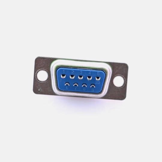
What Is a DB9 Connector?
The DB9 connector features a D-shaped shell to ensure proper orientation when connecting. The 9 pins (or sockets in female versions) are arranged in two rows, with 5 pins on the top and 4 on the bottom. This compact design is suitable for low-profile applications.
The connector comes in two main types:
DB9 Male Connector: Have pins and are typically used on cables.
DB9 Female Connector: Have sockets and are often found on equipment or devices.
Key Features of DB9 Connectors
Durable Construction: The metal shell provides mechanical strength and shields against electromagnetic interference (EMI).
Compact Design: Ideal for devices where space is limited.
Versatile Applications: Commonly used for RS-232 serial communication, connecting peripherals like mice, keyboards, and modems.
Customization: Can support different pin configurations and wiring for varied uses.
Common Applications of DB9 Connectors
Serial Communication: Widely used in RS-232 interfaces to connect computers, printers, and industrial equipment.
Automation and Control Systems: Frequently seen in programmable logic controllers (PLCs) and industrial machines.
Networking Equipment: Used in switches, routers, and legacy systems.
Testing and Prototyping: Found in diagnostic and development tools for electronics.
DB9 Pinout Diagram
Here’s a standard pinout for a DB9 connector used in RS-232 communication:

Advantages of DB9 Connectors
Reliable Connection: Secure locking mechanism ensures a stable link.
Broad Compatibility: Works with many legacy and modern devices.
Easy Maintenance: Simple design allows for straightforward repairs or replacements.
8 notes
·
View notes
Text
funny thing with retro PC hardware is how the further back in history you go, the less you can really expect the mainboard to do for you.
you take a modern mainboard and it'll likely have most functions and features you're likely to need already integrated by default, be it sound, network, WiFi... there's usually even going to be video out from whatever barebones GPU is very likely integrated into the CPU by default, as well as a plethora of USB ports for whatever peripherals or other devices you might possibly want. It's basically almost a complete system in and of itself - just add a CPU, RAM, and some kind of storage medium and off you go. Plenty of boards of today will even have built-in support for plugging in fancy chassis RGB lighting straight into the mainboard itself.
Not so with older mainboards - the one I'm looking at using for my retro build project supports basically the typical two channels of IDE/Parallel ATA for a total of four main drives of whatever combination of hard- and optical, a single floppy drive, two PS/2 ports, one keyboard one mouse, a parallel LPT port, a few serial COM ports, an old AT DIN-5 keyboard port, and - shockingly - two USB ports that I'm guessing are ancient 1.0 standard. And that's it. There's no sound, no graphics, no networking - that's all stuff you have to add via expansion cards. You basically cannot use this computer at all without adding at least a graphics card - the Power On Self Test (or POST) will fail and straight up refuse to boot the system if no graphics card is detected. You go back far enough in history to the original IBM PC and it won't even have integrated hard drive support, necessitating an expansion card just to add fixed storage space.
And this is basically why the PC is such an inherently flexible platform - it was and is built pretty much grounds up to be extensible, providing the option to add just about whatever functions and features you might require via expansion slots built on open standards, allowing pretty much anyone with the prerequisite know-how and manufacturing capabilities to build their own. With the relative ease and low cost of circuit board manufacture of today combined with the ready access to powerful microcontrollers like the Raspberry Pi Pico, there's a good number of hobbyists making expansion cards that can more or less be programmed to do pretty much whatever.
Though this is technically still possible to do on modern PCs, the relative speed and complexity involved with modern PCI Express interfaces makes it far less accessible than making your own ISA expansion cards.
8 notes
·
View notes
Text
Understanding the Functionality of Samsung Refrigerator PCB Main Assembly

Samsung refrigerators have become essential appliances in modern households, offering innovative features and advanced technologies to ensure food preservation and convenience. The (Printed Circuit Board) PCB Main Assembly serves as the brain of the refrigerator, coordinating various functions and ensuring optimal performance.
Components of the Refrigerator PCB Main Assembly
The Refrigerator PCB Main Assembly consists of several essential components, each playing a crucial role in the refrigerator's operation.
Microcontroller: It is the central processing unit (CPU) and the computer performs programmed instructions to coordinate communication between the components.
Sensors: The ambient parameters (temperature, humidity, door status) supply critical information for regulation.
Relays: You control the flow of electricity to the compressor, fan motors, and defrost heater.
Capacitors: It will help you store the electrical energy and help to regulate voltage, and guarantee that the PCB is operating reliably.
Resistors: Protect sensitive components from harm by limiting the flow of electricity across certain circuits.
Diodes: Allow current to flow exclusively in one direction to avoid reverse polarity and safeguard components from damage.
Connectors: Facilitate electrical connections between the PCB and other refrigerator components to ensure seamless integration.
Working Principle PCB Main Assembly
The PCB Main Assembly operates on a set of programmed instructions that determine its behavior depending on sensor input and user command. The micro controller continuously monitors sensor input such as the reading of the temperature from the refrigerator compartment, and freezer. The microcontroller controls the transition of the compressor on, or off or the speed of the fan and also the defrost cycles based on the sensor data as to how to keep the temperature and humidity at the optimal level. In addition to the other refrigerator components, for example, display panel and user interface, the PCB Main Assembly provides feedback and enables users’’ interaction. The PCB Main Assembly incorporates safety features of overload protection and temperature sensors to protect the refrigerator from damage and to protect the user.
Communication Protocols
Data can be communicated to other components through microcontrollers by communication protocols like UART (Universal Asynchronous Receiver Transmitter), SPI (Serial Peripheral Interface), and I2C (Inter Integrated Circuit).
UART is used to transfer real-time data from a microcontroller to external devices like display panels and temperature sensors.
There is a power of communication SPI and I2C for the communication of integrated circuits associated with the PCB Main Assembly for efficient data transfer and synchronization between components.
Troubleshooting and Maintenance
Common issues with the Samsung Refrigerator PCB Main Assembly include sensor failures, relay malfunctions, and power supply issues, which can affect the refrigerator's performance.
To solve PCB Main Assembly problems, we can use diagnostic methods, like running self-tests and checking the error code.
The assembly can stay longer depending on the main, such as cleaning dust and debris from the PCB and securing appropriate ventilation.
The PCB Main Assembly is an important component of the Samsung refrigerator systems since it organizes several functions to contribute to the overall efficiency of the refrigerator and food preservation. Fore-knowledge of the PCB Main Assembly and the way it is constructed can assist users in likely managing problems in their fridges.
2 notes
·
View notes
Text
A Deep Dive into Interface & Connectivity Semiconductors: Market Opportunities and Challenges
The rapid acceleration of digital transformation across industries has ushered in a critical dependence on robust data communication systems. At the heart of these systems lie interface and connectivity semiconductors, which serve as essential conduits for transferring data between integrated circuits, sensors, and peripheral devices. Whether it is automotive, consumer electronics, industrial automation, or telecommunications, the ability of devices to communicate effectively defines their functionality and performance. The significance of these semiconductors is steadily increasing as devices grow smarter, more connected, and more autonomous.
Connectivity demands are evolving in complexity and scope. Advanced applications require high-speed data transmission, low latency, signal integrity, and resilience against electromagnetic interference. The role of interface and connectivity semiconductors, therefore, is not just to bridge data paths but to ensure seamless, reliable communication under increasingly demanding conditions. As markets grow more competitive and consumer expectations rise, semiconductor manufacturers are tasked with not only meeting technical requirements but also innovating at the architectural level to stay ahead of the curve.
The Role of Interface & Connectivity Semiconductors
Interface and connectivity semiconductors provide the vital infrastructure that allows systems and subsystems within electronic devices to interact efficiently. These chips manage data protocols, handle voltage level translation, and mitigate noise in data paths, enabling high-fidelity signal transfer. Their functionality extends from simple serial interfaces to sophisticated high-bandwidth interconnects that support emerging technologies like artificial intelligence, 5G, and autonomous vehicles.
As electronic systems grow more complex, the role of these semiconductors becomes increasingly critical. In automotive systems, for instance, various subsystems—ranging from infotainment units to advanced driver-assistance systems (ADAS)—need to communicate swiftly and reliably. Similarly, in consumer electronics, users demand seamless interaction between components such as cameras, displays, and storage devices. Interface and connectivity semiconductors make these interactions possible by supporting a diverse array of standards and physical media.
Furthermore, these semiconductors play a foundational role in enhancing system scalability and modularity. Designers can develop systems with swappable modules or components without sacrificing performance, thanks to well-engineered interface chips. The abstraction they provide allows manufacturers to iterate on designs without overhauling the entire architecture, thus accelerating time-to-market and reducing development costs.
Market Dynamics Driving Growth
The market for interface and connectivity semiconductors is experiencing robust growth, driven by several converging trends. First and foremost is the explosive proliferation of connected devices, from smartphones and tablets to industrial sensors and medical devices. The demand for high-speed, reliable communication in these devices has propelled investments in advanced interface technologies.
The automotive sector, in particular, represents a burgeoning opportunity. With the shift toward electric and autonomous vehicles, there is a growing need for high-bandwidth communication channels between components like LiDAR sensors, cameras, and central processing units. This trend is complemented by the increasing complexity of vehicle infotainment systems and the integration of advanced navigation and telematics.
Meanwhile, in the industrial space, the advent of Industry 4.0 has catalyzed a surge in machine-to-machine communication. Factories are evolving into smart manufacturing hubs, requiring resilient and fast communication among robots, controllers, and cloud-based analytics platforms. Interface and connectivity semiconductors serve as the glue that holds these complex networks together, ensuring that data flows securely and efficiently.
Technological Innovations and Trends
The evolution of interface and connectivity semiconductors is marked by significant technological advancements aimed at overcoming traditional limitations. One of the key trends is the miniaturization of components. As devices become more compact, there is a need for smaller semiconductor packages that can still handle high data rates and power requirements. Innovations in 3D stacking and system-in-package (SiP) designs are addressing these needs effectively.
Another important trend is the integration of multiple interface standards within a single chip. Multi-protocol transceivers reduce the number of components required, simplifying board layout and reducing power consumption. This is particularly beneficial in space-constrained applications such as wearables and mobile devices. Furthermore, advances in signal conditioning, such as equalization and pre-emphasis, are enhancing signal integrity over long and noisy channels.
Power efficiency is also a growing concern, particularly in battery-operated and environmentally sensitive applications. Engineers are developing interface semiconductors that consume less power without compromising performance. These improvements contribute to longer device lifespans and lower environmental impact. As a result, sustainability has become an increasingly important design consideration in the semiconductor industry.
Challenges in Development and Deployment
Despite the exciting growth prospects, the development and deployment of interface and connectivity semiconductors come with a host of challenges. One of the primary hurdles is ensuring compatibility with a wide range of industry standards and legacy systems. Manufacturers must strike a balance between supporting new protocols and maintaining backward compatibility, which often requires complex design strategies.
Signal integrity is another critical challenge, especially as data rates increase. As frequencies rise, the susceptibility to noise, crosstalk, and electromagnetic interference also grows. This necessitates meticulous engineering of both the semiconductor and the surrounding PCB layout to maintain performance. Additionally, thermal management becomes a more pressing concern as power densities increase.
Supply chain constraints can also impede the rapid deployment of new interface technologies. Global disruptions, such as those seen during the COVID-19 pandemic, have highlighted the vulnerabilities in semiconductor manufacturing and logistics. Ensuring a stable supply chain, therefore, becomes essential for meeting market demand and maintaining product timelines.
Competitive Landscape and Key Players
The interface and connectivity semiconductor market is highly competitive, featuring a mix of established players and innovative startups. Leading semiconductor manufacturers have leveraged their scale and R&D capabilities to develop cutting-edge solutions that cater to a broad range of applications. These include companies known for their leadership in high-speed data interfaces, power-efficient transceivers, and robust physical layer implementations.
In addition to large corporations, a growing number of specialized firms are focusing on niche applications such as automotive Ethernet, USB-C, and industrial fieldbus systems. These companies often bring innovative approaches and agility to the market, helping to drive technological progress. Strategic partnerships, mergers, and acquisitions are common as companies look to expand their capabilities and market reach.
Collaborative efforts with industry standards bodies also play a vital role. By participating in the development of new interface specifications, companies can influence the direction of technology and ensure that their products align with future market needs. This collaborative model fosters innovation while ensuring a level of interoperability that benefits the broader ecosystem.
Regulatory and Standardization Factors
The development and deployment of interface and connectivity semiconductors are heavily influenced by regulatory and standardization considerations. Industry standards ensure that devices from different manufacturers can interoperate effectively, which is crucial for fostering market adoption. Organizations such as the IEEE, USB-IF, and MIPI Alliance play central roles in defining and maintaining these standards.
Compliance with electromagnetic compatibility (EMC) and safety regulations is mandatory for products intended for use in consumer, automotive, and industrial environments. These regulations vary by region, necessitating a thorough understanding of global compliance requirements during the design phase. Failure to meet these standards can result in costly redesigns, delays, and market access restrictions.
Environmental regulations, such as those related to hazardous substances and energy efficiency, further shape the design and manufacturing of semiconductors. Manufacturers must adopt sustainable practices and materials to comply with regulations like RoHS and REACH. These requirements are not just legal obligations but also key factors in building trust with environmentally conscious consumers and clients.
Strategic Opportunities Ahead
Several strategic opportunities are emerging within the interface and connectivity semiconductor space. One of the most promising areas is the continued integration of artificial intelligence (AI) and edge computing. These technologies demand rapid and reliable data transfer, which opens up new use cases for high-performance interface chips.
The transition to electric and autonomous vehicles also presents significant opportunities. Modern vehicles are becoming data centers on wheels, requiring robust and high-speed connections between sensors, processors, and control units. The adoption of MIPI A-PHY as a standardized communication protocol for automotive applications highlights the growing need for specialized interface solutions.
In the realm of industrial automation, the move toward decentralized control and real-time analytics necessitates low-latency, high-reliability communication links. Interface semiconductors designed for deterministic networking and time-sensitive applications will play a crucial role in enabling the smart factory of the future.
Navigating Market Complexities
Entering the interface semiconductor market requires a nuanced understanding of application-specific requirements, customer expectations, and competitive dynamics. OEMs and system integrators seek partners who can deliver not just chips, but comprehensive solutions that address performance, reliability, and scalability. This has led to a rise in value-added services, including design support, custom firmware, and system-level validation.
Design cycles are becoming shorter, and time-to-market pressures are intensifying. Companies must invest in simulation tools, prototyping platforms, and agile development practices to stay ahead. Additionally, customer engagement models are shifting toward co-development and joint innovation, particularly in high-stakes markets like automotive and aerospace.
Building strong customer relationships and offering differentiated value are key to thriving in this environment. Companies that can demonstrate deep application expertise and provide tailored solutions will have a competitive edge. This customer-centric approach aligns well with the strategies of leading OEM Semiconductor providers who prioritize integration, performance, and longevity.
The Future of Connectivity Semiconductors
Looking forward, the interface and connectivity semiconductor industry is poised for transformative change. Innovations in materials, such as the use of gallium nitride (GaN) and silicon carbide (SiC), promise higher efficiency and better thermal performance. These materials are particularly valuable in high-power and high-frequency applications.
Quantum computing, although still in its infancy, represents another frontier. The ultra-sensitive nature of quantum bits will necessitate entirely new paradigms of data interfacing and signal integrity. Early research and prototyping in this area suggest that interface technologies will need to evolve rapidly to meet future demands.
Interdisciplinary collaboration will be critical in shaping the next generation of connectivity solutions. Cross-functional teams involving materials scientists, electrical engineers, software developers, and system architects will drive innovation. As the industry moves forward, the ability to integrate and optimize at both the chip and system level will determine long-term success.
Conclusion
Interface and connectivity semiconductors are more than just components—they are enablers of modern digital life. From smart homes and connected cars to automated factories and cloud computing, the need for fast, reliable data communication is ubiquitous. The industry is brimming with potential, shaped by emerging technologies, evolving standards, and a relentless demand for performance.
As the ecosystem grows more interconnected, the importance of these semiconductors will only intensify. Solutions like the Interface & Connectivity Semiconductors platform are paving the way for scalable, high-performance architectures. Those who can navigate the complexities of design, regulation, and market dynamics will be well-positioned to lead in this dynamic and essential sector.
0 notes
Text
Introduction to Lin Bus and Special Devices for Electrostatic Surge Protection

1、 Introduction to Lin Bus
A. Definition of Lin Bus
Lin bus is a serial communication bus suitable for communication between automotive electronic control units (ECUs).
B. Characteristics of Lin Bus
The Lin bus adopts a single end drive and differential transmission method, which has the characteristics of high-speed transmission and strong anti-interference performance.
C. Application scope of Lin bus
The Lin bus is mainly used for communication between electronic control units (ECUs) in automobiles, such as engine control units, transmission system control units, body control units, and so on. The emergence of the Lin bus enables data exchange and communication between ECUs of different brands, systems, and functions, thereby improving the overall performance and safety of automobiles.
2、 Problems with Lin Bus
A. Hazards of static surges
Static surges and other factors can damage the performance and stability of the Lin bus.
B. Stability and reliability issues of Lin bus
There are also some problems with the Lin bus in practical applications.
3、 Design of electrostatic surge protection
A. Hardware protection measures
The design of electrostatic surge protection needs to start from both hardware and software aspects. In terms of hardware, measures such as protective circuits can be taken to limit electrostatic surge voltage, such as using protective circuits composed of TVS diodes, inductors, capacitors, etc.
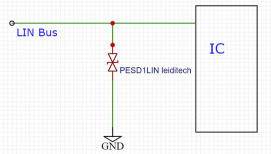
Suggestions for the layout of ESD devices
a) Place the device as close as possible to the input or connector.
b) Minimize the path length between the device and the protected line.
c) Keep parallel signal paths to a minimum.
d) Avoid running protected conductors in parallel with unprotected conductors.
e) Minimize the conductive circuits of all printed circuit boards (PCBs), including power and ground circuits.
f) Minimize the transient return path length to ground.
g) Avoid using shared transient return paths to common ground points.
h) Try to use ground planes, multi-layer printed circuit boards, and ground through holes as much as possible.
B. Software protection measures
In terms of software, error Check digit (CRC) and other technologies can be used to detect errors in data transmission, so as to ensure the reliability of data.
4、 The Importance of Lin Bus in the Field of Automotive Electronics
A. Advantages of Lin Bus
The Lin bus has the characteristics of high-speed transmission and strong anti-interference performance.
B. The Application Prospects of Lin Bus
In the future field of automotive electronics, the Lin bus will still play an important role and play an important role.
Summary
The interface protection of electronic products requires the use of overvoltage protection devices. Many engineers are aware of the need to use protection devices, but due to improper selection or failure to follow the design principles of ESD circuit PCB, the product fails static or EMC testing, wastes manpower and financial resources, and causes product delays or over design, resulting in cost pressure. Leiditech Electronics provides customers with electromagnetic compatibility EMC design services, providing laboratory testing for free. We aim to efficiently and conveniently complete the design for our customers. We hope that more customers can quickly pass EMC’s projects and improve product reliability as much as possible.
Shanghai Leiditech Electronic Electromagnetic Compatibility Laboratory provides free testing and peripheral electrostatic protection reference circuits.
If you’d like to learn more or have any questions, don’t hesitate to reach out:
Visit us at [en.leiditech.com] #LinBus#AutomotiveElectronics #SurgeProtection #EMC #ElectromagneticCompatibility #ESD #TechDesign #AutomotiveTech #VehicleInnovation #CircuitProtection #ElectronicsEngineering #CarSafety #Leiditech
0 notes
Text
0 notes
Text
Top GUI Frameworks and Display Protocols for Embedded Product Development in 2025
In today’s embedded systems, GUIs aren’t just screens — they’re the core of user interaction. Whether you're developing a wearable, an industrial controller, or a smart appliance, creating a seamless graphical user interface (GUI) is critical. This blog explores how to select the right type of LCD touch display, communication protocols, and GUI design tools that align with your product needs.

As a leading board bring-up company, Silicon Signals provides end-to-end board bringup services, with specialization in GUI porting and development using platforms like Qt, LVGL, EmWin, and GTK. Let’s dive into the key components to consider.

Types of LCD Touch Displays
Capacitive Touch Screens
Projected capacitive displays are widely used in consumer electronics like smartphones and tablets. They offer a smooth, responsive multi-touch experience, supporting gestures like pinch-to-zoom and swipe. These displays detect the conductivity of your fingers and perform exceptionally well in dry, clean environments.
Key Benefits:
Multi-touch support
High durability and sleek design
Fast response time
Limitations:
Not ideal for environments where gloves or non-conductive materials are used
Resistive Touch Screens
Resistive displays consist of two layers (plastic and glass) separated by a gap. When pressure is applied, the layers touch, registering the input.
Ideal for: Industrial and rugged environments where gloves or styluses are often used.
Advantages:
Can be operated with any object
Lower cost
Reliable in harsh environments
Drawback:
Requires more pressure, offers less responsiveness than capacitive touch
Display Communication Protocols
Choosing the right communication interface between your display and the processor is crucial for performance and system optimization.
SPI (Serial Peripheral Interface)
SPI is a widely-used protocol in embedded systems, especially when working with lower-resolution screens. It’s simple to implement and works well with basic touch GUIs.
Best suited for: Small displays (~480x360 resolution)
Benefits: Low resource requirements, easy integration on MCUs
Limitation: Not ideal for high-speed or high-res displays
DSI (Digital Serial Interface)
Developed by the MIPI Alliance, DSI is ideal for high-resolution and high-refresh-rate displays with fewer I/O pins required.
Best suited for: Mid-to-high-end embedded systems
Benefits: Power-efficient, scalable, and compatible with modern display controllers
Limitation: Licensing fees due to proprietary technology
HDMI
Used primarily in embedded Linux or high-performance products, HDMI offers the highest quality in terms of audio-visual integration.
Best suited for: Advanced GUIs in medical, aerospace, or industrial systems
Benefits: Combines audio and video, HDCP for secure content, supports large resolutions
Limitation: Requires a more powerful processor and consumes more power
GUI Development Tools & Libraries
Once you've selected your hardware, it’s time to choose a software tool that helps you design and port the GUI effectively. As a board bringup service provider, we at Silicon Signals have deep expertise in GUI porting using Qt, LVGL, EmWin, GTK, and Crank Storyboard.
1. Qt Framework
Qt is a professional-grade development platform used extensively in automotive, medical, and industrial applications.
Language: C++ and QML
Features: Cross-platform, hardware acceleration, built-in protocol support (HTTP, FTP, etc.)
Ideal for: Performance-sensitive, scalable GUIs
Note: Commercial license required for product deployment
We offer advanced Qt porting services for embedded Linux, Yocto-based boards, and RTOS platforms.
2. Crank Storyboard
Storyboard simplifies GUI development with drag-and-drop features, Photoshop imports, and support for animations and 3D elements.
Benefits: Designer-friendly, OS and platform agnostic, embedded engine optimization
Best for: Teams with both design and embedded development backgrounds
Limitation: Requires a license for commercial products
3. LVGL (Light and Versatile Graphics Library)
LVGL is ideal for resource-constrained microcontrollers, with footprint requirements as low as 64kB flash and 8kB RAM.
Languages: C and MicroPython
Platforms: STM32, ESP32, Raspberry Pi, PIC, etc.
GUI Builder: Beta version available
Strengths: Free, open-source, portable
Limitations: Limited for complex UIs or animations
Our team excels in integrating LVGL on custom MCUs and porting it for FreeRTOS and bare-metal systems.
4. EmWin by SEGGER
EmWin is a highly efficient, commercial-grade GUI library optimized for MCUs.
Developed by: SEGGER Microcontroller
Best for: Medical and industrial applications where reliability is non-negotiable
Strength: Real-time performance, minimal resource usage, certified for safety-critical applications
Limitation: Licensing and complexity
We provide EmWin integration services for NXP, STM32, and Renesas-based boards.
5. GTK (GIMP Toolkit)
GTK is a popular GUI library often used in Linux systems and is open-source.
Language: C (bindings available for Python, C++, etc.)
Best for: Embedded Linux systems where scalability and flexibility matter
Drawback: Not suitable for MCUs with limited RAM and Flash
Our engineers can port GTK-based UIs on embedded Linux devices, optimizing for performance and footprint.

Why Silicon Signals?
As a leading board bring-up company, Silicon Signals provides a one-stop solution for embedded product development. From hardware validation and board bringup services to GUI design and porting on popular frameworks like Qt, LVGL, TouchGFX, GTK, and EmWin — we ensure your product is market-ready with a seamless user experience.
Whether you need to develop a medical device UI, a rugged industrial HMI, or a sleek consumer interface, our engineers can help you choose the right display, protocol, and GUI framework.
Ready to design a powerful GUI for your embedded product? Reach out to our engineering team at [email protected] for a free consultation.
#embeddedtechnology#embeddedsoftware#embeddedsystems#linux kernel#androidbsp#linuxdebugging#android#aosp#iot development services#iotsolutions#embeddedgui#guidevelopment#guitools
0 notes
Text
MS-CF20 ATX Motherboard for Intel Arrow Lake-S CPUs

MS-CF20: Next-Gen ATX Motherboard with 15th Gen Intel Arrow Lake-S Processors and Legacy Support
Strong ATX motherboard MS-CF20 supports 15th-generation Intel Arrow Lake-S Series CPUs and has the Intel W880 chipset. By supporting next-generation CPUs and legacy capabilities, the MS-CF20 provides unsurpassed versatility for current and older systems to meet the needs of advanced computing applications.
Power and performance optimised
For Intel Core U9/U7/U5, Pentium, and Celeron CPUs, the MS-CF20 uses the latest Intel 15th Gen Arrow Lake-S technology. New processors perform well in demanding and AI-driven applications because to their greater core counts, instructions per clock, and energy efficiency.
The board's four DDR5 UDIMM slots provide ECC and non-ECC memory up to 5600 MT/s and 192GB, giving data-intensive applications unsurpassed performance.
Advanced Graphics and Displays Support
VGA, DisplayPort (DP), and HDMI monitors make multitasking and visualisation easier on the MS-CF20. This makes it perfect for digital signage, control centres, and industrial automation with several high-resolution panels.
Good Network and Storage Connectivity
Four RJ-45 2.5GbE LAN ports on MS-CF20 provide server-grade and data processing networking. The board has four SATA 3.0 ports, two M.2 M Key slots, and SATA RAID 0/1/5/10 for safe data management.
Extended Expansion and I/O Interfaces
To satisfy various application needs, the MS-CF20 offers these features:
Accelerators, GPUs, and networks fit in one PCIe x16 (Gen 5) or two x8 and four x4 slots.
Two USB 3.2 Gen 1 ports, three USB 2.0 ports, and eight USB 3.2 Gen 2 connections connect fast peripherals.
Industrial-grade serial connectivity options include 10 COM ports (2 RS-485, 8 RS-232).
Audio connections, PS/2, GPIO, and TPM 2.0 for security are included.
Supporting Legacy
PS/2 Port: This port enables vintage keyboards and mice in industrial and automation situations that require reliability and low latency input.
PCI Slot: Supports legacy expansion cards for automation, legacy hardware support, and industrial control systems.
VGA connectors work with old displays and projectors in control systems, factory automation, and long-lifecycle applications.
Ten serial COM ports (one back and nine inside): COM1/2 supports Ring/0V/5V/12V Autoflow (default, Ring) for RS-232/422/485. The COM3-10 supports RS-232 with 0V/5V/12V Autoflow for diverse serial connection and industrial compatibility.
Reliability and Industry Standards
For reliable remote administration and monitoring, the MS-CF20 uses cutting-edge SMBus, I2C, PMBus, and Intel AMT 19.x technologies. Multi-system fan connections improve thermal management, and chassis intrusion detection provides physical security.
Key MS-CF20 Features
15th-generation Arrow Lake-S CPUs with Intel W880 chipset
4 DDR5 ECC/non-ECC UDIMM slots, 192GB.
HDMI, DP, and VGA displays.
Quad 2.5GbE LAN ports
Flexible Gen 5 and Gen 4 PCIe extension
Four SATA 3.0 and two M.2 M slots support RAID.
Built-in TPM 2.0, COM ports, GPIO, PS/2, USB 3.2, and PCI slot.
Previous PCI, VGA, COM, and PS/2 support.
ATX Power's advanced thermal and security features
Target Uses
The MS-CF20 supports high-performance computing systems like:
Production lines, process automation, and industrial machinery may be managed and monitored by industrial automation and control systems.
Real-time processing and analysis of massive amounts of data need data processing servers.
Transport Systems: Connects fleet, traffic, and logistical systems reliably.
Security and surveillance platforms: Powers analytics, real-time monitoring, and HD video streaming.
Medical imaging and data processing provide fast, accurate processing of medical imaging data for healthcare systems and diagnostics.
For intelligent edge and Internet of Things applications, Edge AI and Machine Learning Systems provide AI inference and real-time data processing.
Robotics and autonomous vehicles: Provides high-performance computing for real-time decision-making, automation, and navigation.
Helps manage resources in smart infrastructure, grid control, and energy monitoring.
Broadcast and streaming servers: Ensure reliable content distribution, live streaming, and high-bandwidth media delivery.
old System Integration: Integrates old devices, displays, and peripherals via PS/2, PCI, and VGA to extend industrial and corporate system lifetimes.
The MS-CF20 provides performance, connection, and dependability for today's most demanding applications while maintaining industrial historical compatibility.
#technology#technews#govindhtech#news#technologynews#MS-CF20 ATX Motherboard#MS-CF20#ATX Motherboard#Intel Arrow Lake-S CPUs#MSI MS-CF20#15th generation Intel Arrow Lake-S Series CPUs
0 notes
Text
Introduction The role of radiology in autopsy has been extended to include multidetector computed tomography (CT) and magnetic resonance (MR) imaging. According to Thali et al (2003), the term Virtual Autopsy or Virtopsy refers to the technique of postmortem imaging with multidetector CT and/ or MR imaging. Conventionally, in forensic investigation and autopsy, the use of full-body radiography is well established and routinely applied to document “fractures, injury patterns, occult injuries, and foreign body and metallic fragmentation localization” (Levy, Abbott, Mallack et al, 2006, p.522). Full body radiography also helps in identification of human remains when conventional methods such as fingerprinting or DNA analysis cannot be used, or are not available. Thesis Statement: The purpose of this paper is to investigate the new development of virtual autopsy in forensic science, and identify its advantages and disadvantages over conventional autopsy procedures that have been employed until recently. Virtual Autopsy with the Help of Multidetector Computed Tomography The application of imaging methods for non-invasive documentation and analysis of relevant forensic findings in living and dead persons has not kept abreast of enormous technical development of imaging methods. Forensic radiology is now a rapidly growing interdisciplinary subspeciality of both forensic medicine and radiology. The new modalities that are now increasingly being promoted for use in forensic investigations include Computer Tomography (CT) including spiral multislice, and Magnetic Reso-nance Imaging or MRI (Thali et al, 2007). The VIRTOPSY project aims to utilize radiological scanning to upgrade low-tech documentation and autopsy procedures in the contemporary high-tech field of medicine. The purpose of this is to improve scientific value, and to increase significance and quality in the forensic field. The term VIRTOPSY is the combination of the terms virtual and autopsy. OR Human—machine interfaces consist of the multimodal devices used to present information to VT users. For multimodal VT applications, advances in peripheral connections to the computer are the single largest issue. When an input device is connected, such as а body or limb tracker, а serial port is generally utilized, а port typically designed for character input and not high-speed data transfer. А solution to the input device connectivity issue that is available on commodity computing is the great unsolved problem. At some point, this input-port speed problem needs to be solved, and that resolution must be included on mass-marketed PCs or their descendents. Visual displays, especially head-mounted displays (HMDs), have come down substantially in weight but are still hindered by cumbersome designs, obstructive tethers, suboptimal resolution, and insufficient field of view, see the “HMD/VR—Helmet Comparison Chart, ” Bungert, 2001. ) Recent advances in wearable computer displays (е.g., Microvision, MicroOptical), which can incorporate miniature LCDs directly into conventional eyeglasses or helmets, should ease cumbersome design and further reduce weight (Lieberman, 1999). There are several low- to mid-cost HMDs (InterSense's InterTrax i-glasses, Olympus Eye-Trek FMD, Interactive Imaging Systems' VFX3D, Sony Cybermind, Sony Glasstron, and Kaiser ProViewXL) that are lightweight (approximately 39 g to 1,000 g) providing а true resolution of only about 60 K pixels.. For multimodal VT applications, advances in peripheral connections to the computer are the single largest issue. When an input device is connected, such as body or limb tracker, serial port is generally utilized, port typically designed for character input and not high-speed data transfer. solution to the input device connectivity issue that is available on commodity computing is the great unsolved problem. At some point, this input-port speed problem needs to be solved, and that resolution must be included on mass-marketed PCs or their descendents. Visual displays, especially head-mounted displays (HMDs), have come down substantially in weight but are still hindered by cumbersome designs, obstructive tethers, suboptimal resolution, and insufficient field of view, see the "HMD/VR-Helmet Comparison Chart, " Bungert, 2001. ) Recent advances in wearable computer displays (.g., Microvision, MicroOptical), which can incorporate miniature LCDs directly into conventional eyeglasses or helmets, should ease cumbersome design and further reduce weight (Lieberman, 1999). Read the full article
0 notes
Text
For sell Dimatix Spectra Galaxy JA 256 series: JA 256/30 or JA256/50 or JA256/80
For sell Dimatix Spectra Galaxy JA 256 series: JA 256/30 or JA256/50 or JA256/80
Price: $1,150.00 Find more cheap dimatix spectra at www.indraminer.shop
The Spectra Galaxy JA 256/30 AAA is a high performance, robust and reliable jetting assembly designed for a broad range of wide format printers at resolutions up to 900 dpi. Two electrically independent piezoelectric slices, each with 128 addressable channels and two separate connecting cables, are combined to provide a total of 256 nozzles. The nozzles are arranged in a single line, at a native 0.010 inch distance between nozzles. The fluid interface and electrical connection are at the top of the jetting assembly and several mounting configurations are possible. This jetting assembly contains serial-to-parallel converters for selecting which jets to fire; all jets can be fired simultaneously or individually.
These Spectra heads are manufactured in the US and passed Dimatix Spectra US quality control tests to ensure the best durability. It carries a manufacturer product warranty.
NOTE: This print head is suitable for VUTEk PressVu 180/600 and 200/600 printers. Note that the print head is supplied in the original Spectra sealed packaged and doesn't include the metallic base manufactured by VUTEk. This part can be reused from old heads.
NOTE: On the VUTEk PressVu 200/600, this print head is used for the colour ink channel. If you need the print head for the white ink channel on the VUTEk PressVu 200/600, please refer to PPHSPGA50 (Spectra Galaxy JA 256/50 AAA)
The following items are expressly excluded from warranty coverage:
defects related, in any way, to the use of non-original inks clogged, missing or deviated nozzles defects related to misuse, abuse, accident, neglect, lack of use, or improper storage when not in use for extended periods defects related to failure to perform periodic maintenance as specified in the user documentation; operation for unintended purposes defects related to improper loading of media all other defects, failures or damage not considered manufacturing defects defects related to third-party applications, software, parts, components, or peripheral devices, including any bulk ink system. defects that are merely cosmetic in nature
0 notes
Note
What was the purpose of the panels of blinking lights on those big mid-century computers? Were they showing calculations in progress?

Excellent question, this is one of my favorite subjects! Blinkenlights serve a number of functions. Hollywood tended to use just the lights to make it look like a computer was busy doing something, but real computers had more than just lights on their front panel. Let's walk through a few examples of use cases with photos of computers I've seen over the years at museums and vintage computer festivals:
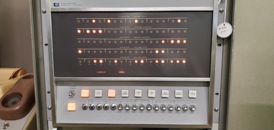
Some front panels were built to be used for diagnostics. Computers like these were primitive enough that they required constant care and debugging to do their jobs, especially the early vacuum tube machines (everything pictured here is transistorized). You could tell what peripherals were being used, but also check the status of registers, carry flags, status flags, data, various buses, etc. It was also a way to see if a program had "gone off into the weeds" and started doing things that were irregular, possibly due to a software bug, or a problem with the hardware.
On many of these machines, you can enter programs directly into the main memory using the front panel, but it's an incredibly tedious process -- something to be avoided if possible. Consider it a last fallback.
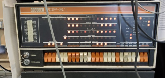
Other times, it's a starting point, which we call "bootstrapping" (this eventually evolved into the term "booting"). You aren't likely to program everything on such a limited interface, but you are more likely to enter in a small program that can tell the computer how to run a more complex peripheral, like a paper tape or punch card reader, or maybe some type of magnetic storage device. Once you can get a program loading off of a larger permanent storage device, you can load up software to interface with a terminal of some kind which is much easier.

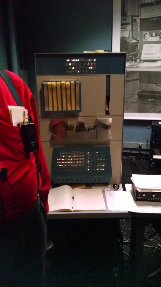
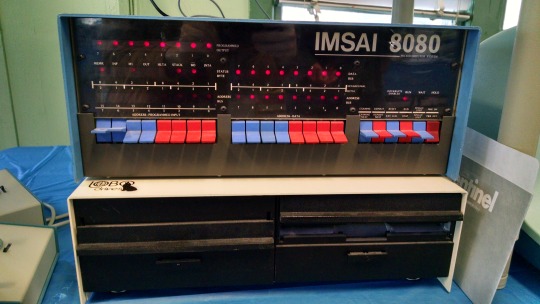
Eventually, the microprocessor made home computers a possibility, but many were only equipped with a front panel out of the box. You would have to add in a serial card, more RAM, possibly some ROMs, and either a teletype or glass terminal in order to get a more sophisticated and intuitive interface from the computer, capable of programming in a higher level language. Some were considered more like trainers, or hobbyist devices, and simply lacked that ability, meaning all you got was a front panel with switches and lights.

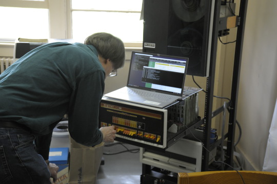
I made my own front panel to see what the experience was all about:

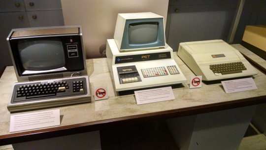
Then everything changed in 1977, with the introduction of these three machines: the TRS-80 Model I, the Commodore PET 2001, and the Apple II. They were what you might call "appliance computers" and they had no need for a front panel.
Hopefully that answered your question!
728 notes
·
View notes
Text
What are the main communication protocols in embedded systems?
Embedded systems rely on various communication protocols to enable efficient data transfer between components, microcontrollers, sensors, and external devices. These protocols can be broadly categorized into serial, parallel, wired, and wireless communication protocols.
UART (Universal Asynchronous Receiver-Transmitter) – A widely used serial communication protocol that facilitates full-duplex data exchange between embedded devices. It requires minimal hardware and is commonly used in debugging and low-speed data transfer applications.
SPI (Serial Peripheral Interface) – A high-speed, full-duplex protocol used for short-distance communication between a microcontroller and peripherals such as sensors, displays, and memory devices. It follows a master-slave architecture and is widely used in real-time embedded applications.
I2C (Inter-Integrated Circuit) – A multi-slave, half-duplex serial communication protocol designed for communication between multiple ICs using only two wires: SDA (data line) and SCL (clock line). It is highly efficient for low-speed applications and is commonly used in sensor integration.
CAN (Controller Area Network) – A robust, message-based protocol widely used in automotive and industrial applications. CAN allows multiple nodes to communicate efficiently without requiring a host computer. It ensures data integrity using error detection and correction mechanisms.
Ethernet – A widely adopted wired communication protocol that enables high-speed data transfer in embedded applications, especially in industrial automation and IoT systems. It supports networking capabilities for remote monitoring and control.
Bluetooth & Wi-Fi – These wireless protocols are essential for modern embedded systems, enabling connectivity in consumer electronics, IoT devices, and smart home applications. Bluetooth is preferred for short-range, low-power communication, while Wi-Fi offers high-speed data exchange over long distances.
Understanding these protocols is crucial for designing efficient embedded solutions. If you want to gain hands-on experience and expertise in these protocols, consider enrolling in an embedded system certification course.
0 notes
Text
tbh one of the things I really like about the PC platform is that it's still - despite all the attempts to make it less so - a relatively open and flexible platform in a way that few others really are, especially these days. You can mix and match hardware from all over the place, sometimes even surprisingly old hardware with the right conversion bits, and several interfacing standards are open and documented to the point where you could literally make your own USB devices or ISA/PCI/PCIe expansion cards given the proper hardware and know-how.
And sure, most of us are never going to have either the tools or technical expertise necessary to make our own PC components or peripherals, but the platform is still open enough to have the kind of wide cross-compatibility where at least in theory any peripheral or piece of hardware could in theory be adapted to work with it - it's simply a matter of someone figuring out a way to make it work and giving others the means to replicate what they did.
I could take literally any kind of input peripheral, be it a joystick, keyboard, gamepad, mouse, or whatever, and chances are someone out there will already have made some kind of adapter to let me hook it up to my PC if I wanted - and in the rare case that none exists to buy, there's still likely to be enough information around that I could use a cheap USB microcontroller as a go-between to make it work.
also look you basically have no idea how excited I am to have discovered that the mainboard I'm looking to get for a much needed PC rebuild somehow has an old 9-pin header for a serial COM port
4 notes
·
View notes
Text
PCIe DC-DC Converter Market - Forecast(2025 - 2031)
PCIe DC-DC Converter Market Overview
PCIe DC-DC Converter Market is analyzed to grow at a CAGR of 16.6% during the forecast period 2021-2026 to reach $9.5 billion. PCIe or PCI Express generally refers to a high speed serial computer expansion bus standard that is designed with more advantages in comparison to older standards. PCIe standards are capable of providing benefits including better performance scaling, lower latency, synchronous rectification, pulse amplitude modulation, larger bandwidth support, higher data speeds and so on making it an ideal choice for various application areas like graphic cards, storage devices, network interface cards, and many other high performance peripherals. With rise in data traffic and need for high performance computing devices and integrated circuits, different generation models be it PCIe 5.0, PCIe 4.0 and so on are selected according to end-use requirements. Increasing rate of data center infrastructure growth as well as shift towards advanced technologies including artificial intelligence and machine learning are considered as some of the major drivers impacting the growth of PCIe DC-DC Converter Market. In addition, investments towards advancing telecom communication infrastructure with 5G technology along with rise of adoption in automotive applications like ADAS systems, infotainment systems and so on are further analyzed to fuel the growth of PCIe technology in the long run.
Report Coverage
The report: “PCIe Industry Outlook – Forecast (2021-2026)”, by IndustryARC covers an in-depth analysis of the following segments of the PCIe industry.
By Generation: PCIe 1.0 & 2.0, PCIe 3.0, PCIe 4.0, PCIe 5.0.
By Form Factor: Mini PCIe, PCIe.
By Product: SLC, MLC.
By Output Voltage: Upto 3.3V, 3.3-5V, 5-10V, 10-15V, 15-24V And Above 24V.
By Output Power: Upto 20W,20-50W,50-100W and Above 100W.
By Application: Graphic Processor Units, Network Interface Cards, Storage Device & Controllers, PCIe Switches (Gen 1, Gen 2, Gen 3, Gen 4 and Gen 5), Servers.
By End Users: Telecommunication, Industrial, Residential, Data Centers (Hyperscale, Colocation, Others), Automotive, Infrastructure, Others.
By Geography: North America, South America, Europe, APAC and RoW.
Request Sample
Key Takeaways
Growing shift towards advanced technologies like artificial intelligence and machine learning along with increasing growth of data center infrastructures is analyzed to significantly drive the PCIe DC-DC Converter Market during the forecast period 2021-2026.
Storage Device & Controllers application segment had accounted for the largest market share in 2020, attributed to the factors including rise of cloud based data storage requirements, infrastructural developments for data centers and so on.
High investments towards research and development activities by some of the key market players such as Samsung Electronics Co. Ltd, Renesas Electronics Corporation and Toshiba Corporation with others have helped in boosting the growth of PCIe across APAC markets.
PCIe DC-DC Converter Market Segment Analysis- By Generation
Based on generation, the PCIe DC-DC Converter Market is segmented under PCIe 1.0 & 2.0, PCIe 3.0, PCIe 4.0 and PCIe 5.0. PCIe 3.0 generation had dominated the PCIe DC-DC Converter Market with 46.5% share in 2020, and is analyzed to grow significantly at a rate of 16.4% during the forecast period 2021-2026. Generation PCIe 3.0 can be referred to as a Gen 3 expansion card comprising of a four-lane configuration, used across some of the major end-use industries be it telecom, data centers and so on. However, with growing advancements towards Gen 4 and Gen 5, adoption of PCIe 3.0 based solutions has been still maintaining a significant growth in the markets, due to its long time presence. Capable of reaching speeds upto 1000 Mbps, PCIe 3.0 architecture incorporate features like enhanced signaling and data integrity, channel enhancements, clock data recovery, pulse amplitude modulation and so on, retaining its market position. Factors including growth in video streaming, video conferencing, online gaming, social networking and many others have surged the internet traffic amidst the COVID-19 pandemic situation, attributing towards the need for PCIe 3.0 interfaces. In addition, usage of PCIe 3.0 has been still in demand owing to rising rate of investments from various key vendors towards developing products with Gen 3 support. In 2020, AMD announced about the launch of A520 chipset, as a part of supporting its third generation Ryzen desktop processors. Through this, the company wanted to help its customers offer a path for future upgrades, based on Zen 3 architecture. Such factors have eventually helped in creating a positive impact towards the deployment of PCIE 3.0 solutions for the end-use markets.
Inquiry Before Buying
PCIe DC-DC Converter Market Segment Analysis- By Application
Based on application, Storage Device & Controllers had accounted for the largest share of 32.1% in 2020, analyzed to grow significantly with a CAGR of 15.5% in the global PCIe DC-DC Converter Market during the forecast period. The need for PCIe had evolved in the storage applications overtime with the introduction of technologies namely SATA Express and Non-Volatile Memory Express. With the shift towards ultra thin laptops, tablet PCs and so on, there is significant need towards connectors used in peripheral devices capable of fitting into narrower spaces. In order to address such requirements, PCI-SIG specified the M.2 connectors, thereby gaining it wide popularity. In addition, growing number of investments towards construction of new data centers or upgradation of existing facilities can be considered as some of the major factors attributing towards its market growth owing to rise of cloud based data storage and improved integrated circuits. NVMe and PCIe have been becoming highly popular owing to technological advancements in the field of solid state storage applications. Deployment of PCIe based solid state drives are raising its demand in the markets serving cloud computing requirements, with comparitively higher data transmission as well as high speed connectivity. Owing to these advantages, PCIe had turned as a popular choice among data centers and telecom sectors due to shift towards high-performance computing while storage applications. In 2021, Interface Concept announced about the launch of a removable SSD mass storage XMC module, named IC-EM2-XMCa, capable of supporting PCIe x1/x2/x4 Gen2/Gen3 interface connection. Owing to its capability of increasing storage capacity upto 2TB, as a part of adding mass storage capacity to any third party Single Board Computer or host carrier board, used across VPX, cPCI or VME systems, thus making it suitable for computing as well as storage-intensive applications. Such factors are further set to propel the growth of PCIe within storage devices or controllers in the long run.
PCIe DC-DC Converter Market Segment Analysis- Geography
APAC had accounted for the largest share of 36.5% in 2020, followed by North America and Europe in the PCIe DC-DC Converter Market, analyzed to grow at a rate of 19.6% during the forecast period 2021-2026. Factors including growing demand for cloud computing services, shift of telecom sector towards advancing network or communication infrastructures and many others have acted as some of the major factors attributing to the market growth. Presence of key players such as Renesas Electronics Corporation, Samsung Electronics Co. Ltd, Toshiba Corporation with many others opting for R& D activities overtime have been also helping in creating significant growth of PCIe across the region. In 2020, Samsung announced about the launch of PCIe 4.0 NVMe SSD (solid state drive), named SSD 980 Pro. This development was meant to help professionals as well as consumers opting for high performance PCs, workstations and gaming consoles, also making it an ideal choice for consumers working with 4K or 8K contents or playing high graphic games. High investments towards building data center facilities as well as growing shift towards improving virtualization, high-performance computing, and many others for automotives is further analyzed to drive the market growth in the coming years. In 2020, China revealed about constructing one of the world's highest-altitude cloud-computing data center in Tibet in order to meet data storage requirements for China as well as various South Asian nations including Bangladesh, Nepal and Pakistan. As per Ningsuan Technology Group, an investment of about 11.8 billion yuan (around USD 1.8 billion) has been planned for this project, which will help in providing services such as video rendering, distance-learning data backup, autonomous driving and so on in the long run. Such construction projects related to data centers are set to drive the need for high-speed switches, storage devices, and so on, impacting the market growth of PCIe during the forecast period 2021-2026.
Schedule a Call
PCIe DC-DC Converter Market Drivers
Increasing growth towards data center infrastructures:
Increasing growth towards data center infrastructures can be considered as one of the vital factors driving the market growth of PCIe. This growth is significantly impacting the need for high-speed devices capable of offering faster data transmission owing to rise of data traffic for optimizing data center facilities. Enterprise workloads have already started migrating towards cloud, which in turn requires the need for high performance computing, virtualization and related applications, making it beneficial for the use of PCIe based devices. In addition to this, with the surging COVID-19 pandemic situation, there is a rapid rise of remote work or work from home, driving the growth of data centers towards handling bulks of data with higher efficiency. Moreover, data centers have been continuously focusing on leveraging hyperscale computing networks to be able to meet growing cloud-based workloads, thereby accelerating the demand towards high-speed networking devices be it PCIe switches, servers, storage devices and many more. Large Enterprises including Microsoft Corporation, Google, Amazon Web Services and many others have been constantly focusing on expanding data center facilities across various regions alongside renovation or upgradation for the existing facilities to cope up with the growing data traffic is further set to propel the demand for PCIe based solutions. As a part of this, in 2021, Microsoft had revealed about its plans of investing about $200 million towards construction of two data centers of around 200,000 square feet outside Chicago, expected to become operational by 2022. Such factors are further set to propel the need for PCIe switches, servers, storage devices and so on owing to conducting various processes be it high-performance computing, optimum network connectivity and many others during the forecast period 2021-2026.
Growing shift towards advanced technologies like artificial intelligence and machine learning:
Growing shift towards advanced technologies including artificial intelligence (AI) and machine learning (ML) can be considered as one of the major drivers impacting the growth of PCIe DC-DC Converter Market. With technological advancements, there is significant rise towards AI or ML based workloads, eventually raising the need for upgraded or new generation of computing architectures. Since AI based applications work on generating as well as processing of massive amounts of data within real-time data speeds, there is significant demand towards various high speed PCIe devices like graphic processor units, switches, controllers and many others, capable of handling large bandwidth requirements at high-speeds. In comparison to traditional CPUs, the need for computational models is rising, owing to growing demand towards high-bandwidth and low latency communication channels. Rise of demands have been eventually attributing towards various PCIe generation models, particularly PCIe 4.0 or PCIe 5.0 for serving such application requirements. Leveraging PCIe technology can help CPU models to keep up with the increasing data flow from edge devices across various enterprises, thereby creating a positive impact on market growth. In 2020, an AI chipmaker, Hailo had introduced high-performance AI acceleration modules, namely M.2 and mini PCIe designed for empowering edge devices. The development of the modules was meant to allow customers integrate high-performance AI capabilities within edge devices, while offering a more flexible and optimized solution. Deployment of such modules can help in accelerating a large number of deep learning based application areas with higher efficiency, thereby creating its significant growth in the PCIe DC-DC Converter Market in the long run.
PCIe DC-DC Converter Market Challenges
Complexities related to designing, implementation or verification:
Designing, implementation or verification related complexities act as one of the major challenges restraining the growth of PCIe DC-DC Converter Market. PCIe based devices are capable of offering improved reliability, availability and many other advantages, gaining it wider adoption across various end-use verticals. However, configurability and complexities for PCIe pose several designing challenges, as the designer needs to read as well as understand various specifications associated with the standard for selecting an option to be incorporated within the designing architecture. In addition, due to its adoption across a broad range of application areas, manufacturing of PCIe in large quantities based on various factors be it voltage, temperature and so on, eventually affects its signal efficiency or integrity, thereby contributing towards high amounts of variation while designing process. Design or verification complexity issues exponentially rises due to need for a huge sample space of configurable features, along with a minimal error while selecting configuration can make the design unsuited for targeted application, thereby causing prolonged time to market. Such factors have been contributing towards lesser adoption of PCIe, while hampering its market growth across various end-use sectors.
Buy Now
PCIe DC-DC Converter Market Landscape
Product launches, collaboration, and R&D activities are key strategies adopted by players in the PCIe DC-DC Converter Market. The key players in the PCIe DC-DC Converter Market include Broadcom Inc., Microchip Technology Inc., Renesas Electronics Corporation, Intel Corporation, Nvidia Corporation, Samsung Electronics Co. Ltd, Toshiba Corporation, Xilinx Inc., PLDA and Texas Instruments among others.
Acquisitions/Technology Launches/Partnerships
In April 2021, Samsung Electronics launched PM9A1 SSD, featuring a PCIe 4.0x4 interface. This development was meant to be used in PCs, specifically for enterprises as well as government agencies dealing with sensitive information with sophisticated security requirements.
In February 2021, Microchip Technology Inc. had introduced PCI Express 5.0 switch solution, Switchtec PFX PCIe 5.0 which is capable of doubling interconnects performance for dense compute, high-speed networking as well as NVM Express storage. Development of the world’s first PCIe 5.0 switch was done to support high density and reliability capabilities, including 28 lanes to 100 lanes and upto 48 non-transparent bridges.
#PCIe DC-DC Converter Market#PCIe DC-DC Converter Market size#PCIe DC-DC Converter industry#PCIe DC-DC Converter Market share#PCIe DC-DC Converter top 10 companies#PCIe DC-DC Converter Market report#PCIe DC-DC Converter industry outlook
0 notes