#i2c module
Explore tagged Tumblr posts
Visit Tumblr Blog
Explore Tumblr blogs with no restrictions, modern design and the best experience.
Last Seen Tumblr Blogs


Fun Fact
In 2020, 44% of users from Denmark used Tumblr daily.
Text
https://www.futureelectronics.com/p/semiconductors--comm-products--i2c/pca9532pw-118-nxp-5033862
I2c bus, Embedded communication, Isolated CAN Transceiver ICs
PCA9532 Series 5.5 V 350 uA 400kHz SMT 16-bit I2C-bus LED Dimmer - TSSOP-24
#NXP#PCA9532PW#118#Comm Products#I2C#Ethernet MAC controller#communication protocol#i2c module#bus#Embedded communication#Isolated CAN Transceiver ICs#High-Speed CAN Transceiver#CAN transceiver#SPI bus#CAN bus lines
1 note
·
View note
Text
https://www.futureelectronics.com/p/semiconductors--comm-products--i2c/pca9532pw-118-nxp-5033862
16-bit I2C-bus LED Dimmer, Embedded communication, image processing,
PCA9532 Series 5.5 V 350 uA 400kHz SMT 16-bit I2C-bus LED Dimmer - TSSOP-24
#NXP#PCA9532PW#118#Comm Products#I2C#16-bit I2C-bus LED Dimmer#Embedded communication#image processing#High-Speed#Isolated CAN Transceiver ICs#CAN bus lines#i2c modules#Can Power Systems#CAN transceiver#Ethernet MAC controller
1 note
·
View note
Text
https://www.futureelectronics.com/p/semiconductors--comm-products--i2c/pca9515adp-118-nxp-5973557
I2C CAN Bus Module, I2C adapter, I2C devices, Serial Peripheral Interface
PCA9515A Series 3.6 V 5 mA 400 kHz 6 pF Surface Mount I2C-bus Repeater - SOIC-8
#Comm Products I2C#PCA9515ADP#118#NXP#I2C CAN Bus Module#I2C adapter#I2C devices#Serial Peripheral Interface#I2C Level Converter#i2c protocol#spi protocol#uart protocol#i2c communication#i2c protocol in embedded system#I2C-bus Repeater
1 note
·
View note
Text


Leftovers & layout - WLED board revision A completed!
Sunday night, Babyada went to bed early, so we finished the capture and layout of our WLED board. Thanks to all the suggestions, we were able to implement quite a few!
For power, use USB C PD with switch-select or DC up to 24V; they are diode-OR'd together with PMEG3050
https://www.digikey.com/short/zv22b0pq
into a massive 5A 24V fuse
https://www.digikey.com/short/43qwwtwm
For the 5V regulator, we picked NCP718ASN500T1G
https://www.digikey.com/short/bb9ncc0n
- it's linear, but we don't need a lot of current at 5V. For 3.3V, we went with our trusty TPS54202
https://www.digikey.com/short/c1wnnf94
Upon request, we kept the ICS-43434 I2S microphone
https://www.digikey.com/short/28zwrrhz
and added an IR 38KHz receiver. For external connectivity, there's an ADC/DAC/GPIO #27 breakout on a JST SH 3-pin and I2C on a StemmaQT/Qwiic 4-pin.
We also added a 2x3 breakout header with 3V, GND, and 3 more GPIO so you could connect an external microphone, IR receiver, buttons, or rotary encoder. The terminal blocks have three 5V level-shifted outputs with 100 ohm in-line resistors and power/ground pairs for each. If you need just one more LED strand, the fourth 5V signal is on the 2x3 block.
Rounding out the design are four mounting holes, a reset button, GPIO #0 user button, GPIO LED, and an individual NeoPixel, which could be useful for testing. It's still pretty small, 2" x 1.3". With an ESP32-Mini module, we can pick a PCB or wFL antenna port, and it's an easy swap to make it use an ESP32-Pico, which has 2MB PSRAM.
Whatcha think - anything else we should add or watch out for?
#wled#esp32#electronics#pcbdesign#electronicsproject#makerlife#hardwarehacking#openhardware#diytech#electronicsengineering#usbc#miccontroller#neopixel#iotdevices#irreceiver#powersupplydesign#smalldesign#esp32mini#hardwarelayout#buildprogress#techinnovation
41 notes
·
View notes
Text
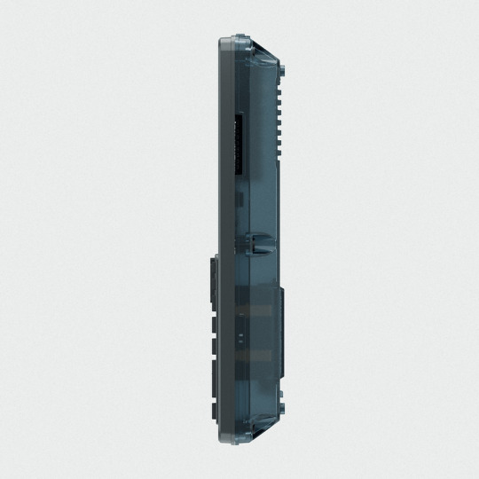
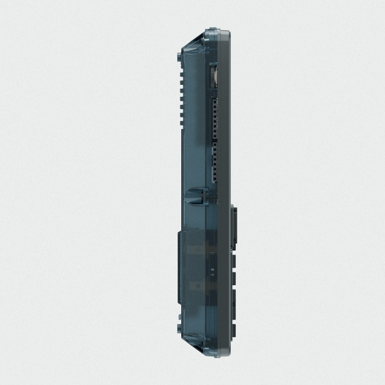
clockwork PicoCalc
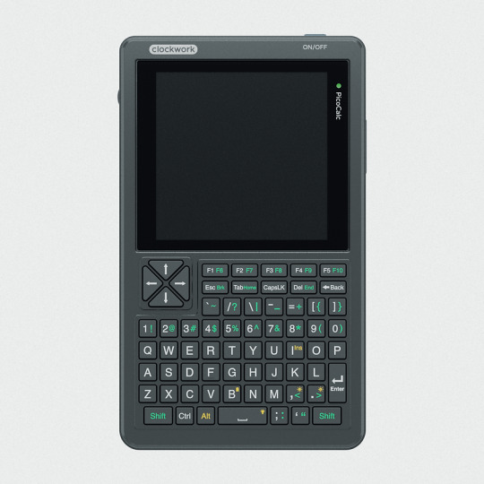


clockwork PicoCalc Back to Basics, rediscover the Golden Age of Computing
Code in BASIC, explore the magic of Lisp, taste the elegance of Unix, play retro games and digital music all in just 260KB memory. Infinite possibilities, inspired by the genius in you!
ClockworkPi v2.0 mainboard
Raspberry Pi Pico 1 H Core module (ARM32-bit Dual-core Cortex M0+, 264KB RAM, 2MB flash)
320x320 4-inch IPS screen (SPI interface)
Ultra-portable QWERTY Backlit keyboard on board (I2C interface)
Dual speaker
ABS plastic shell & 2.5mm Hex key
Tempered glass cover
32GB high-speed SD-card with optimized BASIC firmware
source: clockworkpi.com
7 notes
·
View notes
Text
DIY: Making A Pwnagotchi
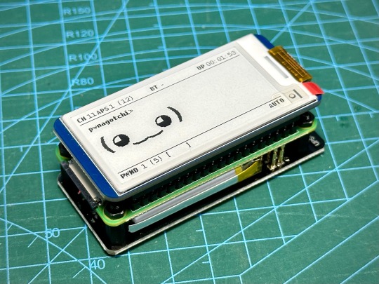

Yes, I know I am very late to the game ... LOL I was meddling with Flipper Zero and war driving, then I came across the Pwnagotchi project. Since I already had the parts to do this lying around in my workshop, I decided to put together my own Pwnagotchi just for fun. Started by hooking up the Waveshare 2.13" Black and White E-Ink Display to a Raspberry Pi running a fresh Raspbian image and downloaded the Waveshare demo code to test the display to make sure it's working properly, since I have not actually used it before. This is a v4 display.

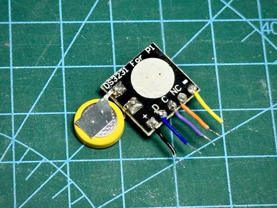
After that, I just followed all the instructions over here to put it all together, including adding a real time clock. I used the DS3231 RTC module designed for Pi, but in order to make it fit into the space between the display and the Pi board, I had to make some modifications. The female header pins on the RTC module was desoldered and short wires were soldered on. The battery also had to be desoldered and resoldered on in a new positionlike below to make the module thin enough. The module was then wrapped in wire tape for insulation. Now, we can just slot the wires into the female header pin holes of the display before we snap it onto the Pi board.
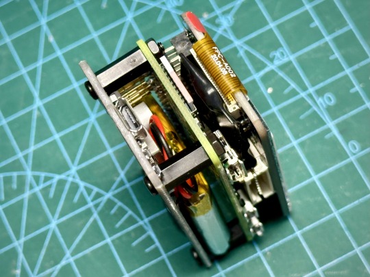
Below, you can see the RTC fits comfortably between the boards. I also attached a UPS Lite v1.2 board. Apparently, the UPS Lite board I had was a clone/knock off. It uses I2C address of 0x32 instead of 0x36 that was used in the original product, so the UPS Lite plugin in Pwnagotchi won't work. Oh well, I will just use it like a normal battery pack.

Now, for the software. The original Pwnagotchi project has not had any new updates for over 2 years, so it's kinda out of date and it doesn't support the newer Waveshare displays. Luckily for us, someone had taken the effort to fork the project and released new versions of Pwnagotchi over here. Note that this requires Raspberry Pi Zero 2 W.
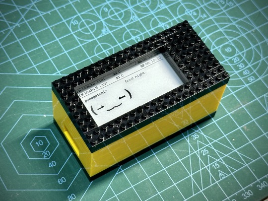
The Waveshare 2.13" E-Ink display that I had was v4, but I found that I had to set the display type to "waveshare_3" in Pwnagotchi settings for it to work properly. Next is to 3D print a case for this, but in the mean time, I used some nano bricks to build a temporary case for it.
That's it for now. Happy hacking!
65 notes
·
View notes
Text
How to Use AHT10 High Precision Digital Temperature & Humidity Sensor with Arduino
Looking to measure temperature and humidity with high accuracy using Arduino? The AHT10 sensor is a compact, I2C-based module that provides reliable data, making it perfect for IoT projects, weather stations, and smart home automation.
What You’ll Learn: ✔️ How the AHT10 sensor works ✔️ Wiring it to an Arduino board ✔️ Writing & uploading the code to get readings ✔️ Tips for stable and accurate measurements
What You Need:
AHT10 Temperature and Humidity Sensor Module
Arduino Nano
0.96 inch SSD1306 OLED Display (128x64, I2C)
Breadboard
Connecting/Jumper Wires
Arduino Nano Cable
Download the Code & Library Arduino AHT10 Temperature and Humidity Sensor Module
Watch the full tutorial on YouTube:
youtube
Follow for more DIY electronics tutorials & Arduino projects!
3 notes
·
View notes
Note
WARNING: LONG ASK INCOMING
For hobby electronics there’s two major kinds of processors: Microcomputers and Microcontrollers. Microcomputers are small full computer systems like the Raspberry Pi, they typically run a general-purpose OS (typically some flavor of Linux) and are useful for the kinds of projects that require basically a full computer to function, but not necessarily individual sensors. They’re a great place to start for people who don’t know a whole ton about programming or working with individual components because they typically can output a true GUI to a screen and have the capabilities of a regular desktop computer. They have a main processor, true RAM, and either large on-board storage space or a way to read a storage device, like an SD card.
Microcontrollers are less complicated (component wise) than microcomputers, but as a result are more difficult for total beginners to begin working with. They’re typically primarily a SoC (System on a Chip) processor without discrete RAM modules and a very small EEPROM (on-ship storage space) and need to have components wired and configured to them to be able to do much more than being a fancy calculator. They’re used for when you need something to carry out electronic functions or get sensor readings, but not necessarily a full operating system, so they’re best suited for small/integrated applications. Your helmet uses a microcontroller to control the LEDs you used in the Cunt Machine post.
I build high-power model rockets as a hobby and with my university team, so I work with both kinds of processor as part of designing payload systems. I typically prefer microcontrollers in these as most of what we do doesn’t need an actual OS to run, and they’re smaller/lighter than microcomputers. One of the advantages of a microcontroller is that it runs a Real-Time OS (RTOS) which forgoes all the user-friendliness of things like windows and linux to instead be the bare minimum backend necessary to run code uploaded into the processor.
The main advantage of using a microcontroller is really that they’re typically a lot cheaper than microcomputers are and are plenty powerful for really embedded applications. They also make other parts of whatever system is being built cheaper/easier to integrate because they require less overhead to function - the raspberry pi needs a minimum of 5 volts of power to work, while a chip like an ESP32-PICO can run at 1.8V.
The main way you make sensors/buttons/peripherals work with a microcontroller is via digital communication busses. There’s a few protocols, the most common being I2C, SPI, and UART. I’ll talk about I2C since that’s generally the most common. With I2C each component is assigned a 2-byte “address” that they’re identified by. When the controller sends a request signal on the I2C data bus, every sensor along the line will return their own signal, marked with their address so that they can be identified. It allows for a large number of devices to be put on the same lines and you can daisy-chain them through each other to the microcontroller.
I’ll be honest I really can’t think of a good way to say much more on the subject as like a starting message because I’ve been working with computers so long all the tech stuff for me is second nature, but if you have any questions ask away I can probably answer them or google them.
.
#AAAAAAAAAAAAAAAAAAAA TY INFORMATION#no yeah this is either really beginner friendly or. friendly to how much i have learned so far#tysm!!!! your insight is consistently so helpful <3#ask#lobsterbitches
27 notes
·
View notes
Text
Characteristics and Applications of LoRa Spread Spectrum Modulation SoC Module
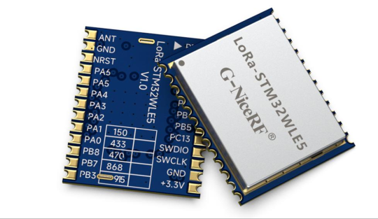
LoRa spread spectrum modulation technology, known for its low power consumption and long-distance transmission capabilities, excels in long-range wireless communication. So, what kind of sparks will this modulation technology create when applied to SOC modules? Let's briefly illustrate this with the LoRa-STM32WLE5 LoRa spread spectrum modulation SOC module developed by NiceRF.
The LoRa-STM32WLE5 wireless module is SOC wireless module the latest developed by NiceRF Wireless. The LoRa-STM32WLE5 adopts ST's STM32WLE5 chip as the main chip, equipped with a high-performance Arm Cortex-M4 32-bit RISC core, operating at a frequency of up to 48 MHz. supporting 256KB flash memory and 64KB operational memory. This module ensures ample storage and processing capabilities. Additionally, the module is equipped with an industrial-grade crystal oscillator, ensuring stable operation in various working environments.
In terms of communication technology, the LoRa-STM32WLE5 adopts LoRa spread spectrum modulation, which features low power consumption and long-distance transmission. This makes the module perform exceptionally well in ultra-long-range wireless communication. It has a high receiving sensitivity of up to -141dBm@BW=125KHz and adjustable transmission power, with a maximum of 22dBm, allowing for transmission distances of over 5000 meters. This characteristic offers extensive application possibilities in fields such as security systems, smart agriculture, and industrial manufacturing.
In addition to its technical features, the LoRa-STM32WLE5 also has advantages such as low power consumption, secure encryption, and multiple interface types. Its sleep current is less than 1uA, and its receive current is less than 8mA, making it suitable for scenarios requiring long battery life and high energy efficiency. Additionally, it supports 256-bit hardware encryption and PCROP read/write protection, ensuring data security and integrity. The support for various interface types, including UART, SPI, I2C, GPIO, and ADC, enables it to meet the interface needs of different application scenarios, offering excellent scalability and flexibility.
In terms of applications, the LoRa-STM32WLE5 wireless module can be widely used in security systems, smart agriculture, industrial manufacturing, and smart home scenarios.
For example: in security systems, it can be used for remote monitoring and alarm systems; in smart agriculture, it can be utilized for agricultural environment monitoring and automated irrigation systems;in industrial manufacturing, it can be applied to equipment monitoring and remote control systems; and in smart homes, it can be used for smart door locks and environmental monitoring.
In the future, with the development of IoT technology and the proliferation of intelligent applications, the LoRa-STM32WLE5 wireless module is expected to demonstrate its value in more fields. For instance, in urban smart construction, it can be applied to smart city traffic systems and intelligent energy management. In the industrial IoT sector, it can be used for remote monitoring of industrial equipment and intelligent production lines. Additionally, as technology continues to advance and costs continue to decrease, the LoRa-STM32WLE5 wireless module will become more widespread and mature, bringing more convenience and possibilities to people's lives.
For details, please click:https://www.nicerf.com/products/ Or click:https://nicerf.en.alibaba.com/productlist.html?spm=a2700.shop_index.88.4.1fec2b006JKUsd For consultation, please contact NiceRF (Email: [email protected]).
4 notes
·
View notes
Text
Introduction of 8Bit PIC MCU PIC16F886T-E/SO, Electronic Components Distributor Introducing the PIC16F886T-E/SO, a high-performance microcontroller that provides the perfect solution for a wide range of embedded applications. With its robust architecture and versatile features, this microcontroller enables developers to create efficient, high-quality designs with ease. MOQ of 8Bit PIC MCU PIC16F886T-E/SO As seen online,MOQ is 100 units.More quantity,inquire us to talk the price support. The PIC16F886T-E/SO is equipped with an 8-bit architecture and a variety of integrated peripherals. It offers up to 32 I/O pins, a 10-bit ADC, and a PWM module, making it ideal for applications ranging from automation to consumer electronics. The microcontroller operates at a maximum CPU speed of 20 MHz and supports multiple operating modes which enhance its efficiency. Applications and Use Cases of the MCU Whether you're designing a home automation system, developing an electronic device, or creating a prototype, the PIC16F886T-E is your go-to choice. Its compatibility with various peripherals and support for reliable communication protocols, such as I2C and SPI, allows seamless integration into your projects. You'll find it widely used in automotive applications, medical devices, and industrial control systems due to its reliability and versatility. Overall, the microcontroller stands out for being user-friendly and well-documented, ensuring a smooth development process. Its combination of performance and features makes it an excellent choice for hobbyists and professionals alike. Experience innovation in embedded systems with the PIC16F886T-E and take your projects to the next level. If you interested with more other integrated circuits,view more to our company business. Read the full article
0 notes
Text
Embedded Systems Course Online – Learn with Technoscripts
Embedded systems are the silent force behind many of the machines & devices we rely on every day. From a simple digital watch to complex automotive control units, embedded systems are quietly doing their job. With the world becoming more tech-driven, learning embedded systems is no longer just an option, it's a necessity for those aiming to work in core electronics & automation.
Technoscripts has created an online embedded systems course tailored for learners who want to build skills from scratch or enhance what they already know. The course is structured with a balance of core theory & hands-on experience, aiming to develop practical skills that actually work in real-world applications.
Why Learn Embedded Systems?
Everywhere you look in industries, homes, vehicles there’s some form of embedded technology at work. These systems are built to carry out specific tasks efficiently. Unlike general-purpose computers, they’re programmed to do one job, & do it well.
Industries such as automotive, telecommunications, healthcare, robotics, & agriculture are using embedded systems in their daily operations. These industries grow, so does the need for professionals who can design, program, & maintain such advanced embedded systems & technologies. If you understand how these small computers operate within machines, you open up a wide range of job and placement opportunities across various sectors.
What This Course Offers
This course is built for learners at all levels. Whether you’re a student from an engineering background or a working professional looking to switch fields, you’ll find the modules easy to follow yet detailed enough to build real skills with our embedded systems course online.
The course includes:
Programming with microcontrollers like 8051, PIC, & ARM
Basics of embedded C & real-time operating systems
Sensor & peripheral interfacing
Understanding & using communication protocols like UART, I2C, SPI
Debugging techniques & h&s-on project development
Each module is created for practical exercises so learners don’t just understand the theory they apply it for industrial use.
Flexible Learning, Expert Guidance
One of the biggest advantages of our course is flexibility. You can attend classes from anywhere, revisit recorded lectures anytime, & ask questions during live sessions. Our trainers are experienced engineers with actual industry exposure. This ensures that you are not just learning concepts but also how they’re used in professional life and career in future.
Who Can Join?
This program is ideal for:
Final-year engineering students
Diploma holders in electronics or related fields
Professionals in IT or electronics wanting to upskill
Anyone interested in electronics & embedded technology
What You’ll Walk Away With
After completing the course, you’ll be able to build embedded projects on your own, & understand how various components work together, & write programs that run on microcontrollers. You’ll also receive a certificate, project experience, & most importantly, the skills that companies actually look for.
Technoscripts also offers placement support for eligible candidates through a dedicated placement cell that connects you with hiring companies in embedded development & R&D roles.
Why Choose Technoscripts?
Courses shaped by real industry needs
Live project work during training
Personal mentorship & doubt-solving
Flexible class timings for working professionals
Certification & job assistance after course completion
Start Learning Today
If embedded systems excite you, & you’re ready to begin your learning journey, now is the time. With Technoscripts’ online embedded systems course, you don’t need to be in a classroom to gain valuable knowledge, you just need the right platform.
For more details or to enroll, visit our website or connect with our admissions team today.
0 notes
Text
Global Real-Time Clock ICs Market to Reach US$ 5.28 Billion by 2032
Real-Time Clock (RTC) ICs Market Analysis:
The global Real-Time Clock (RTC) ICs Market size was valued at US$ 3.41 billion in 2024 and is projected to reach US$ 5.28 billion by 2032, at a CAGR of 6.5% during the forecast period 2025-2032
Real-Time Clock (RTC) ICs Market Overview
This report provides a deep insight into the global Real-Time Clock (RTC) ICs market covering all its essential aspects. This ranges from a macro overview of the market to micro details of the market size, competitive landscape, development trend, niche market, key market drivers and challenges, SWOT analysis, value chain analysis, etc. The analysis helps the reader to shape the competition within the industries and strategies for the competitive environment to enhance the potential profit. Furthermore, it provides a simple framework for evaluating and accessing the position of the business organization. The report structure also focuses on the competitive landscape of the Global Real-Time Clock (RTC) ICs Market, this report introduces in detail the market share, market performance, product situation, operation situation, etc. of the main players, which helps the readers in the industry to identify the main competitors and deeply understand the competition pattern of the market. In a word, this report is a must-read for industry players, investors, researchers, consultants, business strategists, and all those who have any kind of stake or are planning to foray into the Real-Time Clock (RTC) ICs market in any manner.
Real-Time Clock (RTC) ICs Key Market Trends :
Integration with IoT Devices RTC ICs are increasingly being integrated into IoT devices for precise time tracking, enabling power-efficient operations and data synchronization.
Rise in Wearable and Portable Devices The growing popularity of wearables and portable electronics is boosting demand for compact and low-power RTC ICs.
Miniaturization and Power Efficiency Technological advancements are leading to the development of ultra-small RTC ICs with minimal power consumption, ideal for battery-operated devices.
Adoption in Industrial Automation RTC ICs are gaining traction in industrial applications for real-time event logging and process control systems.
Emergence of RTCs with Integrated Memory New RTC ICs come with integrated memory modules for enhanced data storage and backup, especially during power failures.
Real-Time Clock (RTC) ICs Market Regional Analysis :
https://semiconductorinsight.com/wp-content/uploads/2025/01/download-34_11zon-1.png
North America:Strong demand driven by EVs, 5G infrastructure, and renewable energy, with the U.S. leading the market.
Europe:Growth fueled by automotive electrification, renewable energy, and strong regulatory support, with Germany as a key player.
Asia-Pacific:Dominates the market due to large-scale manufacturing in China and Japan, with growing demand from EVs, 5G, and semiconductors.
South America:Emerging market, driven by renewable energy and EV adoption, with Brazil leading growth.
Middle East & Africa:Gradual growth, mainly due to investments in renewable energy and EV infrastructure, with Saudi Arabia and UAE as key contributors.
Real-Time Clock (RTC) ICs Market Segmentation :
The research report includes specific segments by region (country), manufacturers, Type, and Application. Market segmentation creates subsets of a market based on product type, end-user or application, Geographic, and other factors. By understanding the market segments, the decision-maker can leverage this targeting in the product, sales, and marketing strategies. Market segments can power your product development cycles by informing how you create product offerings for different segments. Key Company
Maxim Integrated
Theorycircuit
Renesas Electronics Corporation
ABLIC
Market Segmentation (by Type)
I2C
SPI
Others
Market Segmentation (by Application)
Consumer Electronics
Industrial Applications
Others
Market Drivers
Growing Demand for Consumer Electronics The increasing usage of smartphones, tablets, and smart wearables is a major factor driving the need for reliable real-time tracking components like RTC ICs.
Expansion of Industrial Automation RTC ICs are essential in factory automation systems for scheduling and time stamping, which supports the growth of smart manufacturing processes.
Advancements in Semiconductor Technology Ongoing improvements in IC design and manufacturing are enabling more power-efficient and compact RTC solutions.
Market Restraints
High Cost of Advanced RTC ICs Sophisticated RTCs with extended features and ultra-low power consumption come at a higher cost, limiting adoption among price-sensitive users.
Limited Awareness in Emerging Economies The lack of knowledge and availability in some developing regions can restrict market growth and innovation diffusion.
Complex Design Integration Incorporating RTC ICs into complex electronic systems can be challenging and may require additional design and validation efforts.
Market Opportunities
Growing Adoption in Automotive Electronics RTC ICs are being widely adopted in automotive systems for event logging, GPS timestamping, and dashboard timing applications.
Booming IoT Market As IoT applications grow, the demand for efficient, real-time tracking solutions like RTC ICs increases significantly across sectors.
Rise in Edge Computing and Smart Devices The expansion of edge computing and smart devices presents new opportunities for RTC ICs in ensuring accurate timekeeping in decentralized networks.
Market Challenges
Ensuring Long Battery Life Designing RTC ICs that deliver ultra-low power consumption while maintaining accuracy is a technical challenge for manufacturers.
Supply Chain Disruptions Global semiconductor supply chain issues can impact the availability and lead times of RTC ICs, affecting production and delivery schedules.
Maintaining Accuracy Across Environments RTC ICs must maintain timekeeping accuracy under varying environmental conditions, which can be difficult without adding cost.
Key Benefits of This Market Research:
Industry drivers, restraints, and opportunities covered in the study
Neutral perspective on the market performance
Recent industry trends and developments
Competitive landscape & strategies of key players
Potential & niche segments and regions exhibiting promising growth covered
Historical, current, and projected market size, in terms of value
In-depth analysis of the Real-Time Clock (RTC) ICs Market
Overview of the regional outlook of the Real-Time Clock (RTC) ICs Market:
Key Reasons to Buy this Report:
Access to date statistics compiled by our researchers. These provide you with historical and forecast data, which is analyzed to tell you why your market is set to change
This enables you to anticipate market changes to remain ahead of your competitors
You will be able to copy data from the Excel spreadsheet straight into your marketing plans, business presentations, or other strategic documents
The concise analysis, clear graph, and table format will enable you to pinpoint the information you require quickly
Provision of market value (USD Billion) data for each segment and sub-segment
Indicates the region and segment that is expected to witness the fastest growth as well as to dominate the market
Provides insight into the market through Value Chain
Market dynamics scenario, along with growth opportunities of the market in the years to come
6-month post-sales analyst support
Customization of the Report In case of any queries or customization requirements, please connect with our sales team, who will ensure that your requirements are met.
0 notes
Text

IoT Compute Module / System on Module for Smart Home Automation 🏠 Accelerate your Smart Home Automation solution innovation with our compact, secure, and connectivity-rich IoT Compute module / SoM based on RealTek’s RTL8772x MCU. Ideal for seamless integration and rapid deployment. Key Applications: 🟢 RealTek’s RTL8772x MCU with ARM M55 core operating max @125MHz and with 384K Internal SRAM and 512KB of Internal Flash memory. 🟢 Equipped with TrustZone, AES/SHA/ECC and Secure Boot, Secure OTA. 🟢 On-board NOR Flash, CAN Transceiver and 40-pin Board-to-board connector bringing the on-chip peripheral signals like I2C, QSPI, RGB LCD, ADC, DAC, SPI, UART, SDIO etc. 🟢 Support for BLE 5.3 version, 2.4GHz proprietary, ZigBee and Thread Matter. 🟢 Eases product manufacturers with Time-to-market solution development with only Peripheral board design. 💡 Perfect for applications in: Smart home hubs, lighting control, energy management, HVAC, and security systems.
0 notes
Text

Trying to design a great WLED board 🌈🦄🦃
While waiting for the turkey to finish brining, we're designing a board for using WLED - and we want to make like the bestest board in the whole world.
Our resident mermaid, firepixie
, makes a lot of projects with WLED, and she loves it! So, how can we make something that will be powerful but not too bulky? Here are some things we're thinking about as the design starts to congeal like cranberry sauce:
Power via USB Type C PD with a slide switch that selects between 5, 12, and 20V (24V pixels can usually run fine at 20V) OR via a 2.1mm DC jack. With ideal diodes, it's good for up to 5A from either.
ESP32-Mini module with built-in or optional wFL antenna port. The classic '32 has broad support, even if we'd prefer the 'S2 or 'S3.
There are three output signal terminal block sets, with power and ground for each. They'll be level-shifted to 5V.
Built in I2S microphone (we're still pondering this one).
Stemma QT I2C port to connect external sensors/OLEDs/etc.; separate analog/digital input JST port.
1.3"x1.75" / 33mm x 45mm size with mounting holes.
Anything we're missing, anything that's extraneous?
#electronics#wled#makerspace#esp32#usbtypec#diyprojects#arduino#adafruit#ledlights#hardwaredesign#microcontroller#iot#esp32mini#stemmaqt#circuithacks#ledart#makersgonnamake#powerdesign#tinytech#firepixie
22 notes
·
View notes
Text
Why India’s Drone Industry Needs Periplex: The Hardware Tool Drones Didn’t Know They Needed
As drones fly deeper into critical roles — from agricultural intelligence to autonomous mapping, from disaster response to military ops — the hardware stack that powers them is undergoing a silent revolution.
At the center of that transformation is Periplex — a breakthrough tool from Vicharak’s Vaaman platform that redefines how drone builders can interface with the real world.

What is Periplex?
Periplex is a hardware-generation engine. It converts JSON descriptions like this:{ "uart": [ { "id": 0, "TX": "GPIOT_RXP28", "RX": "GPIOT_RXN28" } ], "i2c": [ { "id": 3, "SCL": "GPIOT_RXP27", "SDA": "GPIOT_RXP24" }, { "id": 4, "SCL": "GPIOL_63", "SDA": "GPIOT_RXN24" } ], "gpio": [], "pwm": [], "ws": [], "spi": [], "onewire": [], "can": [], "i2s": [] }
…into live hardware interfaces, directly embedded into Vaaman’s FPGA fabric. It auto-generates the FPGA logic, maps it to kernel-level drivers, and exposes them to Linux.
Think of it as the “React.js of peripherals” — make a change, and the hardware updates.
Real Drone Applications That Truly Need Periplex
Let’s break this down with actual field-grade drone use cases where traditional microcontrollers choke, and Periplex thrives.
1. Multi-Peripheral High-Speed Data Collection for Precision Agriculture
Scenario: A drone is scanning fields for crop health with:
2 multispectral cameras (I2C/SPI)
GPS + RTK module (2x UART)
Wind sensor (I2C)
Sprayer flow monitor (PWM feedback loop)
ESCs for 8 motors (PWM)
1 CAN-based fertilizer module
The Periplex Edge: Microcontrollers would require multiple chips or muxing tricks, causing delays and bottlenecks. With Periplex:
You just declare all interfaces in a JSON file.
It builds the required logic and exposes /dev/pwm0, /dev/can0, etc.
Zero code, zero hassle, zero hardware redesign.
2. Swarm Communication and Custom Protocol Stacks
Scenario: Swarm drones communicate over:
RF LoRa (custom SPI/UART)
UWB mesh (proprietary protocol)
Redundant backup over CAN
Periplex lets you:
Create hybrid protocol stacks
Embed real-time hardware timers, parity logic, and custom UART framing — none of which are feasible in most MCUs
Replacing Microcontrollers, Not Just Augmenting Them
| Feature | Microcontroller | Periplex on Vaaman | |---------------------------|----------------------------|------------------------------------| | Number of peripherals | Limited (4–6) | Virtually unlimited (30+ possible) | | Reconfiguration time | Flash + reboot | Real-time, dynamic reload | | Timing precision | Software-timer limited | FPGA-grade nanosecond-level timing | | AI compatibility | Not feasible | Integrated (Gati Engine) | | Sensor fusion performance | Bottlenecked | Parallel FPGA pipelines |
Developers Love JSON, Not Register Maps
No more:
Scouring 400-page datasheets
Bitmasking registers for I2C configs
Writing interrupt handlers from scratch
Just declare what you need. Let Periplex do the work. Peripherals become software-defined, but hardware-implemented.
Built in India, for India’s Drone Revolution
Vaaman + Periplex isn’t just about tech. It’s about self-reliance.
India’s defence, agriculture, and logistics sectors need secure, reconfigurable, audit-friendly hardware — not black-box SoCs from questionable supply chains.
Periplex is the hardware engine for Atmanirbhar Bharat in drones.
TL;DR
Periplex lets drones adapt hardware to the mission — instantly.
It replaces tangled microcontroller logic with clean, structured JSON.
It unlocks use cases microcontrollers can’t touch: AI at the edge, dynamic reconfiguration, secure protocol stacks, and more.
And it’s built into Vaaman, India’s first reconfigurable edge computer.
Ready to Get Started?
Explore Vaaman on Crowd Supply Reach out for Periplex SDK access: [email protected]
Raspberry Pi
Drones
Drones Technology
Jetson Orin Nano
Technology
0 notes