#Stepper Motor Driver Module
Explore tagged Tumblr posts
Visit Tumblr Blog
Explore Tumblr blogs with no restrictions, modern design and the best experience.
Last Seen Tumblr Blogs


Fun Fact
The most popular pages on Tumblr are about Minecraft, GIFs, and David J. Peterson.
Text
It works!*
So I (FINALLY) put the final touches on the software for my robot PROTO! (Listen, I am a software person, not a coming-up-with-names person)
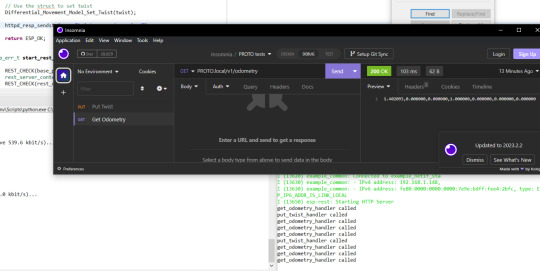
Basically, it is a ESP32 running him. He takes HTTP messages. Either GET odometry, or PUT twist. Both just being a string containing comma separated numbers
Odometry is the robots best guess based on internal sensors where it is (Since PROTO uses stepper motors, which rotates in tiny tiny steps... it is basically counting the steps each motor takes)
Twist is speed, both in x,y and z directions, and speed in angular directions (pitch, roll and yaw). This is used to tell the robot how to move
Now, since PROTO is a robot on two wheels, with a third free-running ball ahead of him, he cannot slide to the side, or go straight up in the air. You can TRY telling him to do that, but he will not understand what you mean. Same with angular movement. PROTO can turn left or right, but he have no clue what you mean if you tell him to bend forward, or roll over.
The software is layered (Which I use a BDD diagram to plan. I love diagrams!)
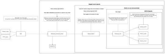
Basically PROTO gets a twist command and hands that over to the Differential_Movement_Model layer.
The Differential_Movement_Model layer translate that to linear momentum (how much to move forward and backwards) and angular momentum (how much to turn left or right). combines them, and orders each wheel to move so and so fast via the Stepper_Motors layer.
The Stepper_Motors turns the wanted speed, into how many steps each stepper motor will have to do per second, and makes sure that the wanted speed can be achieved by the motors. It also makes sure that the wheels turn the right way, no matter how they are mounted (In PROTO's case, if both wheels turn clockwise, the right wheel is going forward, and the left backwards.). It then sends this steps per second request down to the Peripheral_Hub layer.
The Peripheral_Hub layer is just a hub... as the name implies, it calls the needed driver functions to turn off/on pins, have timers count steps and run a PWM (Pulse-width modulation. It sends pulses of a particular size at a specific frequency) signal to the driver boards.
Layering it, also means it is a lot easer to test a layer. Basically, if I want to test, I change 1 variable in the build files and a mock layer is build underneath whatever layer I want to test.
So if I want to test the Stepper_Motors layer, I have a mock Peripheral_Hub layer, so if there are errors in the Peripheral_Hub layer, these do not show up when I am testing the stepper motor layer.
The HTTP server part is basically a standard ESP32 example server, where I have removed all the HTTP call handlers, and made my own 2 instead. Done done.
So since the software works... of course I am immediately having hardware problems. The stepper motors are not NEARLY as strong as they need to be... have to figure something out... maybe they are not getting the power they need... or I need smaller wheels... or I will have to buy a gearbox to make them slower but stronger... in which case I should proberbly also fix the freaking cannot-change-the-micro-stepping problem with the driver boards, since otherwise PROTO will go from a max speed of 0.3 meters per second, to most likely 0.06 meters per second which... is... a bit slow...
But software works! And PROTO can happily move his wheels and pretend he is driving somewhere when on his maintenance stand (Yes. it LOOKS like 2 empty cardboard boxes, but I am telling you it is a maintenance stand... since it sounds a lot better :p )
I have gone over everything really quickly in this post... if someone wants me to cover a part of PROTO, just comment which one, and I will most likely do it (I have lost all sense of which parts of this project is interesting to people who are not doing the project)
129 notes
·
View notes
Text
How Do Power, Motor & Robotics Development Tools Drive Innovation in Automation?

Introduction to Modern Development Ecosystems
As the era of intelligent machines, automation, and smart manufacturing continues to advance, Power, Motor & Robotics Development Tools have emerged as essential components in transforming ideas into functioning prototypes and commercial solutions. These tools serve as the backbone for developing precise and reliable control systems used in a wide variety of sectors—from industrial robotics to electric mobility.
With the increasing integration of microcontrollers, sensors, thermal management components, and electronic controllers, development tools offer a modular and practical approach to building sophisticated electronic and electromechanical systems.
What Are Power, Motor & Robotics Development Tools?
Power, Motor & Robotics Development Tools consist of hardware kits, interface boards, and control modules designed to help developers and engineers test, prototype, and deploy automated systems with precision and speed. These tools make it possible to manage current, voltage, mechanical motion, and real-time decision-making in a structured and scalable manner.
By combining essential components such as capacitors, fuses, grips, cables, connectors, and switches, these kits simplify complex engineering challenges, allowing smooth integration with controllers, microprocessors, and sensors.
Exploring the Primary Toolsets in the Field
Power Management Development Tools
Efficient energy management is crucial for ensuring stability and performance in any robotic or motor-driven system.
Development boards supporting AC/DC and DC/DC conversion
Voltage regulators and surge protection circuits for safe energy flow
Thermal sensors and oils to maintain system temperature
Battery management ICs to control charge-discharge cycles
High-efficiency transformers and current monitors
Motor Control Development Tools
Motor control kits are built to manage torque, direction, and speed across a range of motor types.
H-bridge motor drivers for bidirectional motor control
Stepper motor controllers with high-precision movement
Brushless DC motor driver modules with thermal protection
Feedback systems using encoders and optical sensors
PWM-based modules for real-time torque adjustment
Robotics Development Tools
Robotics kits merge both mechanical and electronic domains to simulate and deploy automation.
Preassembled robotic arm platforms with programmable joints
Sensor integration boards for object detection, motion sensing, and environmental monitoring
Wireless modules for IoT connectivity using BLE, Wi-Fi, or RF
Microcontroller development platforms for logic execution
Mounting hardware and cable grips for secure installations
Benefits of Using Professional Development Tools
Advanced development kits offer more than just experimentation—they serve as stepping stones to commercial production. These tools minimize development time and maximize productivity.
Enhance system performance with modular plug-and-play designs
Enable easy integration with laptops, diagnostic tools, and controllers
Reduce design errors through pre-tested circuitry and embedded protection
Facilitate rapid software and firmware updates with compatible microcontrollers
Support debugging with LED indicators, thermal pads, and status feedback
Key Applications Across Industries
The adaptability of Power, Motor & Robotics Development Tools makes them suitable for countless industries and applications where intelligent movement and power efficiency are essential.
Industrial robotics and pick-and-place systems for manufacturing automation
Smart agriculture solutions including automated irrigation and drone control
Automotive design for electric vehicle propulsion and battery systems
Aerospace applications for lightweight, compact control mechanisms
Educational platforms promoting STEM learning with hands-on robotics kits
Essential Components that Enhance Development Kits
While the kits come equipped with core tools, several other components are often required to expand capabilities or tailor the kits to specific use cases.
Sensors: From temperature and light to current and magnetic field detection
Connectors and plugs: For flexible integration of external modules
Switches and contactors: For manual or automatic control
Thermal pads and heatsinks: For preventing overheating during operation
Fuses and circuit protection devices: For safeguarding sensitive electronics
LED displays and character LCD modules: For real-time data visualization
How to Choose the Right Tool for Your Project
With a vast array of kits and tools on the market, selecting the right one depends on your application and environment.
Identify whether your project focuses more on power management, motor control, or full robotic systems
Consider compatibility with popular development environments such as Arduino, STM32, or Raspberry Pi
Check the current and voltage ratings to match your load and motor specifications
Evaluate add-on support for wireless communication and real-time data processing
Ensure the tool includes comprehensive documentation and driver libraries for smooth integration
Why Development Tools Are Crucial for Innovation
At the heart of every advanced automation solution is a well-structured foundation built with accurate control and reliable hardware. Development tools help bridge the gap between conceptualization and realization, giving engineers and makers the freedom to innovate and iterate.
Encourage experimentation with minimal risk
Shorten product development cycles significantly
Simplify complex circuit designs through preconfigured modules
Offer scalability for both low-power and high-power applications
Future Scope and Emerging Trends
The future of development tools is headed toward more AI-integrated, real-time adaptive systems capable of learning and adjusting to their environment. Tools that support machine vision, edge computing, and predictive analytics are gaining traction.
AI-powered motion control for robotics
Integration with cloud platforms for remote diagnostics
Advanced motor drivers with feedback-based optimization
Miniaturized power modules for wearable and mobile robotics
Conclusion: Is It Time to Upgrade Your Engineering Toolkit?
If you're aiming to build smarter, faster, and more energy-efficient systems, Power, Motor & Robotics Development Tools are not optional—they’re essential. These kits support you from idea to implementation, offering the flexibility and performance needed in modern-day innovation.
Whether you're developing a prototype for a high-speed robotic arm or integrating power regulation into a smart grid solution, the right development tools empower you to transform challenges into achievements. Take the leap into next-gen automation and electronics by investing in the tools that make engineering smarter, safer, and more efficient.
#Power Motor & Robotics Development Tools#electronic components#technology#electricalparts#halltronics
0 notes
Text
Bonsanto, MM, et al. "3D ultrasound navigation in syrinx surgery - a feasibility study." Acta Neurochirurgica 54.4 (2005): 540-1. This article talks about the different designsmof the ultrasounds. It deals with the construction, and assessment of a three-dimensional (3D) ultrasound system which is utilized for the treatment of kidney tumors which are using high-intensity focused ultrasound (HIFU). This tpye of method contains of a therapeutic ultrasound distribution unit (power amplifier, matching circuit, driver, and transducer (1 MHz)) and a 3D positioning of the different component ( microcontroller and stepper motors). The article talks about the structure comprises of software that projects a treatment preparation in keeping with the tumor directs. In order to confirm the competence of the structure for touching the transducer, the placing module was positively driven so that it would cover the cylinders of sizes that are as large as 30 cm (diameter) x 10 cm (height) with step sizes that are as low as 0.05 mm. this artic. This article is helpful because it discusses the several exposimetry experiments that have been done which displayed a very close match that was among experimental and theoretical outcomes. The article did well in talking about the Ex-vivo experiments were achieved and designated the competence of the system to yield a single graze of 0.27 cm width and 0.45 cm measurement, in addition as five abrasions (all that have a diameter of 0.3 cm) at prespecified places. It was hepful in discussing the tempatures. Throughout the ex-vivo trials, temperature checking which was indicated as an upsurge in high temperature that had derived from 37°C to around 60°C inside the cut, while when outside it the temperature stayed about under 39°C. Coyne, Lucy, Kannamannadiar Jayaprakasan and Nick. Raine-Fenning. "3D ultrasound in gynecology and reproductive medicine." Women's Health 12.3 (2008): 67-90. This article discussed the advances that were occurring in medicine on a day-to-day foundation, it was just a matter of time before vital gynecological inquiries, for instance ultrasound, were adapted. Numerous clinicians continue to stay unconvinced by its supposed compensations and 3D ultrasound is not deprived of disadvantages. These mostly narrate to the cost inferences and exercise requirements. The article talks about the 3D ultrasound imaging and how it is still at a comparatively early phase in relationships of its part as an ordinary imaging modality that is in gynecology and reproductive medicine. The article displays how the 3D imaging has more than a few clear assistances that tell to an enhanced three-dimensional orientation and the protest of multiplanar views, of which the coronal plane is particularly useful. It offers a more impartial and reproducible dimension of capacity and vascularity of the area of attention, and an enhanced valuation of usual and pathological pelvic structures through additional post-dispensation modalities, counting tomographic ultrasound imaging and numerous interpretation modalities. It likewise has the advantage of proposing reduced skimming time, the choice of tele-discussion and storing of descriptions for re-evaluation. On the other hand, other than its application in the assessment and differentiation of uterine anomalies, this article very helpful because there is very little indication representing that 3D ultrasound outcomes that are in a clinically pertinent advantage or refutes the necessity for additional study. Upcoming work would guarantee that 3D ultrasound is associated with conventional imaging in randomized tests where the viewer is sightless to the result, merely after which will we actually be capable to evaluate its part in an evidence-based manner. Lweesy, Khaldon, et al. "Design and ex-vivo kidney evaluation of a high-intensity focused ultrasound transducer and 3D positioner." Medical and Biological Engineering and Computing 48.3 (2010): 269-76. The transducer probe is supposed to be the chief section of the ultrasound machine. The device is what will cause the sound waves and then take in the reverberations. It is, in a manner of speaking, the ears and mouth of the ultrasound machine. The too produces and accepts sound waves by means of a code named the piezoelectric (compression power) outcome, which was revealed by Pierre and Jacques Curie in 1880. Inside of the probe, there are many quartz crystals named piezoelectric crystals. When an electric current is put to these crystals, they start to alter in their shape very fast. This is a good article and very helpful to the reader because it enlights the reader on the quick form moves, or sensations, of the crystals create sound waves that travel external. On the other hand, when sound or pressure waves begin to knockout the crystals, they start to create electrical flows. The author did a good job in making sure in displaying for that reason, the similar crystals can be recycled to direct and obtain sound waves. The author also makes sure that they explain that the device also has a sound gripping material to eradicate back likenesses from the probe itself, and an audio lens to aid emphasis the produced sound waves. Muns, Andrea, et al. "Integration of a 3D ultrasound probe into neuronavigation." Acta Neurochirurgica 533.40 (2011): 56-78. This article talks about the Intraoperative ultrasound (iUS) which certainly permits the cohort of real-time information sets all through surgical involvements. It goes into detail depictring how the current innovation of 3D ultrasound probes really has been able to permits the gaining of 3D data sets that are without the necessity to rebuild the capacity by 2D shares. This article describes the incorporation of a tracked 3D ultrasound probe that goes into a neuronavigation. It also explains that an ultrasound device, delivered with both a 2D segment probe and a 3D endocavity transducer, was combined in a steering arrangement with an visual tracking method. Navigation was accomplished by combination of preoperatively which was acquired by MRI data and intraoperatively assimilated ultrasound data that goes on during the course of an open biopsy. This article is very helpful because it explains how the data sets with both probes and how they were learned transdurally and associated. The attainment with the 3D probe, dispensation and imagining of the capacity would just take about 2 min for the entire time. The volume data set which was developed by the 3D probe acts more homogeneous and deals with image that has better quality in contrast with the appearance data learned by the 2D investigation. The addition of a 3D probe into neuronavigation is likely and has sure compensations likened with a 2D probe. The danger of wound can be reduced, and the presentation can be mentioned for convinced cases, chiefly for small craniotomies. Muscatello, A, et al. "Correlation between 3D Ultrasound Appearance and Postnatal Findings in Bilateral Malformations of the Fetal Hands." 11.6 (2012): 138-40. This article discusses how the ultrasounds are used in malformations. It goes into detail explaining how the Malformations of the hand have an occurrence of 1 in about 1,600 births. Ultrasound analysis and cataloging of the incongruity is not continuously stress-free for the reason that of the numerous positions which were taken by the hand. The article describes the circumstance of a 23-year-old patient that had a fetus that was affected by a proportioned and bilateral hand oligodactyly related with malformations of the other fingers. The article was very helpful because it showed how the 3D ultrasound assessment endorsed an exact forecast of the malformation and presented faultless communication with postnatal discoveries. The case exemplifies the involvement of 3D ultrasound to the assessment of fetal limb irregularities. Mahmoud, Ahmed M, et al. "High-Resolution 3D Ultrasound Jawbone Surface Imaging for Diagnosis of Periodontal Bony Defects: An In Vitro Study." Annals of Biomedical Engineering 78.4 (2010): 533-545. This article makes the point that although medical subjects have documented the position of expending ultrasonic imaging, dentistry is only starting to determine its advantage. This has chiefly been significant in the field of periodontics which educates infections that are in the gum and bone tissues that normally surround the teeth. This article displays how the study inspects the probability of utilizing a custom-premeditated high-frequency ultrasound imaging organization to rebuild resolution that is high ( Read the full article
0 notes
Text
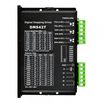
Main functions and maintenance methods of stepper motor drivers
1.Introduction to the working principle of stepper motor drivers The stepper motor driver is an actuator that converts electrical pulses into angular displacement. The stepper motor driver accurately controls the number of steps, speed and direction of the stepper motor by receiving pulse signals from the control system. The working principle of the stepper motor is to convert the electrical pulse signal into angular displacement, and control the angular displacement by controlling the number of pulses, thereby achieving precise control of the motor position.
2.Main components of stepper motor drivers 1.Microprocessor: As the core component of the stepper motor driver, it is responsible for receiving input signals, processing control algorithms and outputting control signals. Microprocessors usually use high-performance, low-power single-chip microcomputers or DSP chips, with rich peripheral interfaces and powerful processing capabilities. 2.Power amplifier: Responsible for amplifying the control signal output by the microprocessor into the driving current required by the motor. The power amplifier usually uses switching power supply technology, with the characteristics of high efficiency, high power density and low noise, and has over-current, over-voltage, short-circuit and other protection functions to ensure the safe and stable operation of the motor. 3.Drive circuit: The bridge connecting the microprocessor and the power amplifier is responsible for converting the control signal into a signal that the motor can recognize.
3.The main functions of the stepper motor driver 1.Pulse distribution: The stepper motor driver controls the movement of the motor by receiving the control signal and converting it into the drive signal of the motor. Specifically, the ring distributor in the driver receives the pulse signal, direction signal and offline signal, and accurately controls the transistor in the power amplifier to turn on according to the instruction of the pulse signal, so as to drive the coil of the stepper motor to be energized. 2.Power amplification: The stepper motor driver provides sufficient power to drive the motor by amplifying the motor drive signal to ensure that the motor can operate normally. The drive module amplifies the motor drive signal and provides sufficient power to the motor to ensure that the motor moves in the specified step length and direction. 3.Precision control: The stepper motor driver achieves precise control of the motor position and speed by accurately controlling the step angle of the motor. This precise control makes stepper motors widely used in CNC equipment. 4.Protection function: The stepper motor driver also has a variety of protection functions, such as undervoltage lockout, overtemperature protection, etc. These functions can improve the stability and safety of the system.
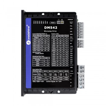
4.Maintenance methods of stepper motor drivers 1.Regular inspection and cleaning: Regularly check whether the connection wires, power cords and switch power cords of the stepper motor driver are broken, and ensure that all connections are firm and there is no short circuit. At the same time, keep the surface of the driver clean to avoid dust accumulation affecting the heat dissipation effect. 2.Power supply system inspection: Use a digital multimeter to check the connection wires of the driver power supply system terminals and the working voltage of the power supply system to ensure that the power supply system is normal, without voltage abnormalities or insufficient power supply. 3.Heat dissipation management: Check whether the heat dissipation setting is proper and ensure that the driver has enough heat dissipation space. You can add heat dissipation equipment such as fans or heat sinks, and ensure that the working environment temperature does not exceed the specified range. 4.Parameter setting check: Check whether the current setting of the driver is correct to ensure that it does not exceed the rated current of the motor. Adjust the pulse width and the maximum step rate of the motor to avoid problems such as inter-turn and lost steps when the motor moves. 5.Environmental management: The stepper motor driver should be stored in a clean, well-ventilated environment with an ambient temperature of -40 to 50°C and a relative humidity not exceeding 95%. Avoid contact with corrosive, flammable gases, oil mist, dust and other impurities. 6.Regular maintenance: Regularly check the various components of the driver, including power cord, fuse, enable signal line, etc., to ensure their normal operation. Replace severely worn parts such as bearings in a timely manner. 7.Troubleshooting: If the driver fails, determine whether it is a common fault such as overvoltage, undervoltage protection, overcurrent, overtemperature, etc. according to the indication of the LED or other methods, and refer to the instructions for use for corresponding processing.
0 notes
Text
Mechatronics Design Excellence with Servotech Services
Introduction to Mechatronics Design
Mechatronics is a multidisciplinary engineering field that integrates mechanical engineering, electronics, computer science, and control systems to create innovative and efficient automated solutions. The modern world relies on mechatronics in various industries, including automotive, aerospace, manufacturing, and healthcare. With increasing technological advancements, businesses require precise and high-quality mechatronic systems to stay competitive.
Servotech Services: A Leader in Mechatronics Design
Who is Servotech?
Servotech Services is a renowned company specializing in mechatronics design, offering top-notch engineering solutions that blend mechanics, electronics, and intelligent control systems. With years of experience in automation and embedded control systems, Servotech has carved a niche in delivering high-performance mechatronic solutions tailored to specific industry needs.
Why Choose Servotech for Mechatronics Design?
Expertise in Multidisciplinary Engineering – Servotech brings together a team of skilled engineers from diverse fields, ensuring a holistic approach to mechatronics design.
Cutting-Edge Technology – The company integrates the latest advancements in artificial intelligence, robotics, and IoT to enhance the efficiency and intelligence of mechatronic systems.
Customization and Flexibility – Servotech tailors solutions based on customer requirements, ensuring optimal performance and cost-effectiveness.
Proven Track Record – With successful projects across various industries, Servotech has established itself as a trusted partner in mechatronics innovation.
Quality Assurance and Reliability – Servotech follows stringent quality control measures, ensuring durable and reliable mechatronic solutions.
Key Services Offered by Servotech
1. Embedded Control Systems
Servotech excels in designing and developing embedded control software and hardware for various applications. These systems enhance automation by enabling real-time decision-making and precise control of mechanical components. Servotech’s embedded solutions are widely used in industrial automation, robotics, automotive systems, and medical devices.
2. Robotics and Automation
Robotics and automation are at the core of modern mechatronics. Servotech provides innovative robotic solutions that integrate advanced sensors, actuators, and AI-driven control algorithms. These systems improve efficiency, productivity, and safety across industries such as manufacturing, logistics, and healthcare.
3. Motion Control Systems
Servotech specializes in motion control solutions, including servo motors, stepper motors, and actuators. These systems ensure precision movement in industrial machinery, CNC machines, robotic arms, and medical equipment. Advanced algorithms optimize performance, reducing energy consumption and increasing operational efficiency.
4. Industrial IoT (IIoT) Integration
The Industrial Internet of Things (IIoT) is revolutionizing manufacturing and industrial processes. Servotech integrates IoT-enabled sensors and communication modules into mechatronic systems, allowing remote monitoring, predictive maintenance, and data-driven decision-making. This connectivity enhances efficiency, reduces downtime, and improves overall system reliability.
5. Prototyping and Testing
Before deploying full-scale solutions, Servotech offers prototyping and rigorous testing services. Through simulation, real-time testing, and iterative design improvements, the company ensures that its mechatronic systems meet the highest standards of performance, safety, and reliability.
Applications of Servotech’s Mechatronic Solutions
1. Automotive Industry
Servotech provides advanced mechatronic solutions for vehicle automation, electric powertrains, and driver assistance systems. Embedded control units optimize fuel efficiency, safety, and performance in modern automobiles.
2. Industrial Automation
Smart factories rely on Servotech’s automation solutions, including robotic assembly lines, conveyor systems, and smart manufacturing tools. These technologies streamline production processes and improve productivity.
3. Medical Devices
Precision and reliability are critical in the medical industry. Servotech develops embedded control systems for surgical robots, diagnostic devices, and patient monitoring systems, enhancing the accuracy and safety of medical procedures.
4. Aerospace and Defense
Servotech contributes to aerospace and defense by designing mechatronic systems for UAVs (Unmanned Aerial Vehicles), avionics, and automated navigation systems. These solutions ensure high performance, security, and reliability in critical missions.
The Future of Mechatronics with Servotech
As industries continue to evolve, the demand for smart, automated, and efficient systems will grow. Servotech remains committed to pushing the boundaries of mechatronics design, integrating AI, IoT, and robotics to create next-generation solutions.
Conclusion
Servotech Services stands as a pioneer in mechatronics design, delivering innovative solutions that drive efficiency, productivity, and technological advancements across various industries. With expertise in embedded systems, automation, robotics, and IoT integration, Servotech continues to shape the future of mechatronics engineering. Businesses looking for reliable and cutting-edge mechatronic solutions can trust Servotech to deliver excellence.
0 notes
Text
Optimizing Performance by Best Practices for PLC Stepper Motor Control Systems
Programmable Logic Controllers (PLCs) are now an integral part of industrial automation. Without a doubt, stepper motor control is one of the most flexible and most important applications among those many. Stepper motors are largely used in manufacturing, robotics, and automations as they offer precise control over position and speed. For effective operation on such systems, though, specific best practices must be followed. Through this guide, we have learned how you can optimize your performance through best practice PLC Stepper Motor Control systems that will allow your automation processes to reach their maximum capabilities.
Understanding PLC Stepper Motor Control
Understanding the best practices also involves understanding the PLC and stepper motor interaction. A stepper motor is a brushless DC motor divided into discrete steps, with precise positional control. A PLC communicates with the motor through driver modules by sending electrical pulses that determine the movement of the motor.
Effective control of these systems can lead to increased accuracy of operation, less consumption of energy, and longer lifespan. This is where optimum performance through best practices for PLC stepper motor control systems comes in handy.
Why Use Stepper Motors with PLCs?
Stepper motors are preferred in automation for several reasons:
Precision: Ideal for applications requiring accurate positioning, such as CNC machines or 3D printers.
Reliability: Durable and capable of maintaining position without continuous power.
Compatibility: Stepper motors work seamlessly with PLCs, allowing integration with other automation systems.
Stepper motors provide many advantages but can still stall, vibrate, or even overheat if their control is not done correctly. For these issues, therefore, look into performance optimization by the best practices of PLC stepper motor control systems.
Best Practices for PLC Stepper Motor Control
1. Proper Selection of Stepper Motor
There are several keys to optimizing your system: First, the stepper motor. Consider the following factors:
Torque and Speed Requirements: The motor must deliver what your application’s operating requirements demand.
Step Angle: A smaller step angle provides for higher resolutions and smoother motion.
Load Capacity: The motor must efficiently handle the weight and inertia of the load.
By choosing a motor that meets your particular needs, you lay the foundation for optimized performance by best practices for PLC stepper motor control systems.
2. Efficient Programming of PLCs
How you program your PLC will make all the difference in system performance. Consider the following aspects while programming:
Pulse Frequency: Tune pulse rates to match motor specs, avoid stalling, or becoming unstable.
Acceleration and Deceleration Ramps: Gradual speed changes minimize mechanical stress on the motor.
Closed-Loop Control: Using feedback systems such as encoders brings about greater precision and error correction.
Good programming practices assure smooth operation and are necessary to optimize performance through best practices for PLC stepper motor control systems.
3. Minimizing Electrical Noise
Electrical noise can cause intercommunication between the PLC and the stepper motor driver to go haywire. For minimizing the noises,
Shield Cables: Use shielded cables, thus protecting signal integrity.
Proper Grounding: Ensure a well-established grounding system for all components.
Separation of Power Lines: Distance signal wires from high-voltage power lines.
These are basic requirements in which to ensure consistent performance and optimize performance by best practice in PLC stepper motor control systems.
4. Regular Maintenance and Inspection
Routine maintenance is also necessary to extend the lifespan of your stepper motor and PLC system. The primary tasks include:
Lubrication: Prevent wear and tear on moving parts.
Tightening Connections: Loose connections can lead to intermittent failures.
Inspecting Wiring: Look for signs of wear or damage in cables.
Maintenance is done consistently in a manner that your system operates on its highest performance, further optimizing performance by best practices for PLC stepper motor control systems.
Enhancing System Efficiency
1. Energy Optimization
Stepper motors consume more power compared to the normal DC motors, and this is especially in holding torque. In order to optimize energy use:
Use a microstepping driver to cut down current at lower speeds.
Implement sleep modes in your PLC program when the motor is idle.
Opt for low power stepper motors when high torque is unnecessary.
Energy-efficient performance means a foundation of optimizing performance by best practices for PLC stepper motor control systems.
2. Integration with Advanced Sensors
Modern PLC systems can integrate with advanced sensors for real-time monitoring and control. Examples include:
Proximity Sensors: Detect the position of objects to trigger motor actions.
Temperature Sensors: Monitor motor temperature to prevent overheating.
Vibration sensors: Identify mechanical issues early.
Sensor integration helps the achievement of automation, improving the PLC stepper motor system by best practices in order to achieve desired performance.
Challenges in PLC Stepper Motor Control
Although stepper motors are reliable, some challenges may appear, such as:
Resonance Issues: Can cause significant vibrations and reduce motor lifespan.
Overheating: Often due to improper settings on current.
Step Loss: It occurs when the motor cannot keep with command pulses.
All these challenges should be addressed by following up the best practices in optimizing performance by the PLC stepper motor control systems.
Conclusion
In the automation world, stepper motors and PLCs will take center stage in providing precision and efficiency. However, the performance in stepper motor control with PLC depends on proper selection, programming, maintenance, and integration with cutting-edge tools. Thus, by perfecting performance with best practices in PLC Stepper Motor Control, you are assured of smoother operations, cost cutting, and longer-lived equipment.
Whether it is a small project in scale or large industrial setup, these practices give a reliable roadmap towards success. Adopt these strategies today and level up in your automation processes!
Originally Published Here:-
0 notes
Text
Top 10 Must-Have ICs for Your Next Electronics Project
Integrated Circuits (ICs) have revolutionized electronics, making complex circuitry compact, affordable, and more reliable. Whether you’re working on a hobby project or designing a professional application, certain ICs are essential for building efficient and functional devices. Here, we’ll go over ten must-have ICs that can elevate your next electronics project.
1. 555 Timer IC
The 555 Timer is a versatile IC known for its wide range of applications, from timing to pulse generation. It’s used in both monostable (one-shot) and astable (continuous) modes, ideal for creating oscillators, timers, and even light flashers. It’s a staple for DIY electronics projects and is compatible with numerous applications.
2. LM317 Voltage Regulator
The LM317 is an adjustable voltage regulator IC that provides a stable output. This IC can regulate voltages from 1.25V to 37V, making it essential for power management in electronic circuits. Ideal for custom voltage needs, it’s useful in battery charging circuits, power supplies, and adjustable voltage systems.
3. ATmega328 Microcontroller
This microcontroller IC powers Arduino boards, making it a favorite among hobbyists and professionals alike. It’s programmable with various I/O pins, analog-to-digital converters, and PWM capabilities, perfect for projects that involve data processing, motor control, or IoT applications.
4. Operational Amplifier (Op-Amp) IC: LM741
The LM741 Op-Amp IC is a general-purpose operational amplifier widely used in analog electronics. It amplifies weak signals and is commonly employed in sensors, audio applications, and signal processing. With a wide frequency response and minimal distortion, it’s an essential IC for audio and measurement circuits.
5. 4017 Decade Counter IC
The 4017 Decade Counter is a popular IC in applications where sequential LED lighting or timing control is required. It’s often used in combination with the 555 Timer to create light chasers or display counters. This IC finds applications in counters, timers, and LED displays.
6. ULN2003A Darlington Transistor Array
For projects involving motors, relays, or high-current components, the ULN2003A is invaluable. This Darlington transistor array provides the necessary current amplification to control multiple loads from a single microcontroller or sensor. It’s often used in stepper motor drivers and relay control applications.
7. NE5532 Audio Amplifier
The NE5532 is an audio amplifier IC with excellent noise performance, making it ideal for high-fidelity audio applications. Its low distortion and wide frequency response suit it well for audio mixing, preamplifiers, and general sound processing tasks. Audio engineers and hobbyists alike rely on this IC for quality sound amplification.
8. LM3915 Dot/Bar Display Driver
If you’re creating visual indicators, the LM3915 is a great choice. This IC is used to drive LED bar graphs or dot displays, making it a favorite for visual VU (Volume Unit) meters or battery level indicators. With its easy cascading options, it’s well-suited for applications needing multiple LED levels.
9. MAX232 Serial Communication IC
The MAX232 is crucial for projects involving RS-232 communication. It converts signals from a serial port to signals suitable for TTL-based digital logic circuits. This IC is essential for any project requiring serial communication, like microcontroller-based systems or data transfer applications.
10. ESP8266 Wi-Fi Module
For IoT projects, the ESP8266 Wi-Fi Module IC is a game-changer. This IC provides Wi-Fi capabilities to microcontroller-based projects, allowing remote control and data monitoring. It’s widely used in smart home applications, sensor networks, and any project that requires wireless data transfer.
Conclusion
These essential ICs provide versatility, reliability, and functionality, which makes them indispensable in electronic projects. Whether you’re building a simple timer, creating complex IoT devices, or designing audio applications, these ICs are vital tools. Stocking up on these components will ensure your toolbox is ready for almost any project that comes your way.
If you’re looking to get started with these ICs, you can find a wide selection and Buy Electronic Components Online from Blizzcartz. For more details and the best prices, check out Electronic Components Online in India.
#Buy Electronic Components Online#Best Prices for Electronic Components in India#Electronic Components for DIY Projects
0 notes
Text
L9110S Stepper Motor Driver Module | High Performance & Compact Design
L9110S Stepper Motor Driver Module | High Performance & Compact Design Introduction to the L9110S Stepper Motor Driver Module Key Features of the L9110S Stepper Motor Driver Module Applications of the L9110S Stepper Motor Driver Module Technical Specifications How to Use the L9110S Stepper Motor Driver Module Compatibility with Arduino and Other Platforms Why Choose the L9110S Stepper Motor…
0 notes
Text
GET L239D MOTOR DRIVER
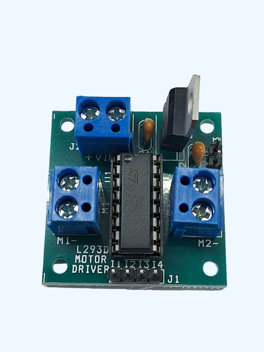
This L293D driver module is a medium power motor driver perfect for driving DC Motors and Stepper Motors. It uses the popular L293D motor driver IC. It can drive 4 DC motors in one direction, or drive 2 DC motors in both the directions. This motor driver is perfect for robotics and mechatronics projects for controlling motors from microcontroller, switches, relays, etc. Perfect for driving DC and Stepper motors for micromouse, line following robots, robot arms, etc.
0 notes
Text
DIY Laser Engraver Essentials: Understanding Laser Parts
A DIY laser engraver is a fantastic tool for hobbyists and creative individuals who want to add a personal touch to their projects. Crafting a laser engraver from scratch allows you to customize the machine according to your specific requirements and can save you a significant amount of money compared to purchasing a commercial device. In this article, we will explore the essential parts of a DIY laser engraver and provide valuable insights into how they function.
1. laser module : The Core Component
The laser module is the essential part that produces the laser beam for engraving. Depending on the materials you plan to work with, you can select from various types of laser modules, such as CO2 or diode lasers. The power rating of the laser module is critical, as it determines the depth and precision of your engravings.
2. Laser Driver: Ensuring Stable Operation
The laser driver is responsible for powering the laser module and regulating its operation. It controls the current and ensures that the laser functions consistently. A good laser driver is vital for maintaining the quality and reliability of your engravings, preventing fluctuations that could affect your results.
3. Frame and Motion System: Stability and Precision
The frame provides the structural support for your laser engraver, while the motion system ensures precise movement of the laser module. A solid frame, typically made from aluminum or steel, reduces vibrations and enhances engraving accuracy. The motion system, which includes stepper motors and rails, enables smooth and controlled movement across the workpiece.
4. Control Board: Directing the Engraver
The control board acts as the command center of your DIY laser engraver. It interprets instructions from your engraving software and controls the laser module and motion system accordingly. Popular control boards include GRBL-based and Arduino-based systems, known for their compatibility and reliability.
5. Power Supply: Providing the Necessary Energy
The power supply unit delivers the required electrical power to all components of the laser engraver. It is crucial to choose a power supply that can provide stable and adequate power to ensure the smooth operation of your machine. An unreliable power supply can lead to performance issues and potential damage to your components.
6. Cooling System: Managing Heat
Engraving generates heat, especially with high-power laser modules. A cooling system, such as a fan or water cooling setup, is necessary to manage this heat and prevent overheating. Proper cooling not only protects your laser module but also ensures consistent performance and prolongs the life of your DIY laser engraver.
By understanding these key components and their functions, you can successfully build a DIY laser engraver tailored to your specific needs. This knowledge empowers you to create a versatile and efficient tool, enhancing your projects with personalized and professional-quality engravings.
0 notes
Text

I have also been working on the 2:1 reduction gearbox that I want to add to each of the motor/wheel assemblies. I have printed the gears on the Prusa FDM for now until I get the design worked out, but I intend to resin print the gears for the final iteration. The picture here also shows a bunch of DRV8825 micro-stepping driver modules that I intend to use to drive the Nema 17 stepper motors. One module per motor obviously. Although I have bought ten of them so that I can ultimately make a second identical robot and have a couple of spare modules too. No way am I going to repeat the annoyance of no spare parts when something fails in the future.
0 notes
Text
Solutions to faults during operation of stepper motor drivers
1.Basic understanding of stepper motor drivers A stepper motor driver is an actuator that converts electrical pulses into angular displacements. It drives the stepper motor to rotate a fixed angle in the set direction by receiving control signals. The stepper motor driver is an important component of the stepper motor system, responsible for converting the control signal into the current and voltage required by the stepper motor to drive the motor for precise angular or linear displacement. The working principle of the stepper motor driver is to convert the input pulse signal into a drive current signal to control the angular displacement of the stepper motor. The speed of the motor is proportional to the pulse frequency, so the speed can be accurately adjusted by controlling the pulse frequency, and the positioning can be accurately achieved by controlling the number of pulses. The stepper motor driver has high positioning accuracy and stability, and can subdivide each step into smaller steps through the subdivision function, thereby improving positioning accuracy and stability.
2.The main structure of the stepper motor driver 1.Ring distributor. Generate the switching waveform signal processing of the motor in different states according to the requirements of the input signal. Perform PWM modulation on the switching signal waveform generated by the ring distributor and filter and shape the related waveform. 2.Protection circuit. When the winding current is too large, a shutdown signal is generated to shut down the main circuit to protect the motor driver and motor winding. 3.Sensor. Real-time monitoring of the position and angle of the motor, and the signal generation device is transmitted back.
3.Solutions to faults during operation of stepper motor drivers 1.The motor does not rotate or rotates slowly: The stepper motor driver needs to receive the correct pulse signal to control the motor rotation. If the motor does not rotate or rotates slowly, first check whether the pulse signal source is working properly, ensure that the driver input terminal is connected correctly, and check whether the motor wiring is correct to eliminate the motor itself. 2.Overheating: The stepper motor driver may overheat when working for a long time or overloaded. Improve the heat dissipation conditions, add fans or heat sinks, ensure that the working environment temperature is suitable, and avoid long-term overload operation. 3.Excessive noise: Abnormal noise during motor operation may be caused by bearing damage or loose internal parts. Check whether the motor bearing is damaged, re-tighten the loose internal parts, and adjust the driver current setting. 4.Overcurrent protection: The driver has an overcurrent protection function. If the output current exceeds the rated value, the driver will cut off the power supply to protect the motor and itself. Check the power supply and motor load, and readjust the current setting. 5.Communication error: If the driver and controller are controlled by communication, communication errors may indicate that the driver cannot work properly. Check the communication line and settings to ensure stable communication.
4.Precautions for using stepper motor drivers
1.Power management: The quality of the power supply directly affects the performance and power consumption of the driver. The ripple size of the power supply affects the accuracy of the subdivision, and the suppression ability of the power supply common mode interference affects the anti-interference of the system. Therefore, for applications with higher requirements, users must pay attention to improving the quality of the power supply. In addition, the installation of the driver should ensure good ventilation, and regularly check whether the cooling fan is running normally. 2.Signal line processing: When wiring the system, the principle of separating the power line (motor phase line, power line) from the weak current signal line should be followed to avoid interference with the control signal. When it is impossible to wire separately or there is a strong interference source, it is best to use shielded cable to transmit the control signal. Using a higher level control signal is also meaningful for resisting interference. 3.Initial operation check: Do not connect all the lines at the beginning. You can connect the most basic system first, and then complete all the connections after confirming that it is running well. Carefully observe the sound and temperature rise of the motor. If any abnormality is found, it should be stopped and adjusted immediately. 4.Environmental adaptation: Due to the drastic changes in the storage and transportation environment temperature, condensation or frost is easy to occur. At this time, the driver should be placed for more than 12 hours. After the driver temperature is consistent with the ambient temperature, it can be powered on. If stored in an unsuitable environment for a long time, the quality of the product should be retested before operation.
Source:https://medium.com/@porterbickford69/solutions-to-faults-during-operation-of-stepper-motor-drivers-7fc1e964767f
0 notes
Text
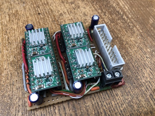
Stepper motors can of course be driven by standard H-Bridge's, but it is not the ideal solution. The best way is to use dedicated Stepper driver modules like those used with 3D printer control boards that provide Micro Stepping for smooth motion control.
This is my four stepper motor driver board. It measures 60mm x 55mm containing four A4988 Stepper driver modules to drive four short body Nema 17 motors. Current limiting on each is set to 700mA which provides powerful motor control without over heating each of the very compact motors.
0 notes
Text
A4988 Pinout: A Comprehensive Guide
Discover the functionality and versatility of the Stepper Motor Driver Module A4988 Pinout, a crucial component in the world of robotics and automation. Let’s delve into the key details, with a specific focus on the A4988 pinout for a clearer understanding.
Stepper Motor Driver Module A4988
The A4988 is a stepper motor driver module that plays a pivotal role in controlling the precise movements of stepper motors. Whether you’re working on a 3D printer, CNC machine, or any other project requiring accurate motor control, the A4988 is a go-to choice.
A4988 Pinout Configuration
Understanding the A4988 pinout configuration is essential for effectively integrating the A4988 into your projects. Here’s a breakdown of the key pins:
MS1, MS2, MS3 (Microstep Resolution): These pins determine the microstep resolution, allowing you to set the stepping mode for the stepper motor. Configuring these pins enables fine-tuning of motor movement.
VMOT (Motor Power Supply Voltage): Connect this pin to the motor power supply voltage (typically 8V to 35V) to ensure the proper functioning of the stepper motor.
GND (Ground): Establish the ground connection by linking this pin to the ground of your power supply or microcontroller.
VDD (Logic Power Supply Voltage): Provide the logic power supply voltage (typically 3V to 5.5V) to this pin to power the internal logic circuitry of the A4988.
DIR (Direction Input): Control the direction of the stepper motor by connecting this pin to a digital output on your microcontroller.
STEP (Step Input): Trigger individual steps of the stepper motor by connecting this pin to another digital output on your microcontroller.
RESET (Reset Input): This pin resets the internal translator circuit, and it is optional to use.
SLEEP (Sleep Input): Putting the A4988 into sleep mode is achieved by connecting this pin to a digital high signal.
Read More: A4988 Pinout
#A4988#stepper-motor#microcontroller#Arduino#Raspberry-Pi#electronics#pinout#wiring#tutorial#DIY#project#hardware#software#programming#electronics-projects#microcontroller-projects#Arduino-projects#Raspberry-Pi-projects#open-source#maker#fabrication#prototyping#engineering#technology#innovation#learning#education
0 notes
Text
BMW Adaptive Headlight Malfunction: Symptoms & Solutions

We're aware of the value that adaptive headlights can provide, especially when navigating a winding road. Adaptive headlights are a standard feature in almost all contemporary vehicles, including those made by the famous German automaker BMW. This article outlines some of the most common causes of adaptive headlight malfunction in BMW vehicles. Plus, as you continue reading, you will learn about various symptoms and fixes for BMW adaptive headlight issues.
BMW Adaptive Headlights: Aiding the Driver's Visibility on Dark, Curved Roads
Yes, adaptive headlights do exactly that :):):) They ensure that the driver gets a clearer vision of what's ahead when taking a turn at night. Just so you know… It's a fully automated system that allows the headlight bulbs to swivel based on the vehicle's speed, elevation, and steering angle. And, to make this happen it relies on many different types of sensors, a computer unit, and servos.
As you can see, there is a complex process at work behind your BMW's adaptable headlights. This entire system could be rendered unusable by an insignificant technical issue. The following is a list of possible causes for a BMW's adaptive headlights to fail. Please, take a look…
Reasons Your BMW's Adaptive Headlights Might Fail
Explanation #1- Defective control module
The control module is crucial in determining how your BMW's adaptive headlights operate, so if it breaks down, the adaptive headlights won't function as they should. Checking the control module should be your first course of action if your BMW's adaptive headlights aren't working.
Explanation #2- Bad stepper motor
When you corner, it's the stepper motor that controls the beam projector to ensure better visibility. Your BMW adaptive headlights won't function properly if the stepper motor has a technical glitch. If it’s the stepper motor that causing your adaptive headlights to behave erratically replace it.
Explanation #3- Cracked seal
To keep moisture, dust, and other foreign substances from getting into the headlight, a seal has been put in place. Cracks may eventually appear in the headlight seal. Water can leak into the headlight through a damaged seal, which will lead to issues. As a result, its adaptability may get negatively affected.
BMW Adaptive Headlight Failure Symptoms
Clue #1- Headlight only turn right (or, left)
The fact that your BMW adaptive headlights only turn left (or, right) is the first sign that they are damaged. Adaptive headlights don't aim their light beam in a specific direction as conventional headlights do. When you turn right or left they should turn accordingly. If they are unable to do so, there is a problem.
What to Do?
Typically, this sort of issue arises when the stepper motor is malfunctioning. So, check the stepper motor… if you find a glitch, repair or replace the entire unit.
Clue #2- Error message
Error messages are one clue that your BMW's adaptive headlights are malfunctioning. So, if your BMW displays messages like adaptive headlight failure, adaptive headlight malfunction, adaptive headlight control malfunction, etc., it's time to call a technician to trace the issue to its root and get it fixed.
What to Do?
Have someone inspect your BMW's adaptive headlight system, specifically the control unit if you notice any of the aforementioned error messages while driving. With the right equipment, a professional may be able to solve the issue.
Clue #3- Flickering light beams
The pulsating of light beams is another clue that your BMW adaptive lighting system has problems. This is most commonly seen when the stepper motor that controls the beam projection fails. Such an issue could also be brought on by a loose or damaged wire and a faulty sensor.
What to Do?
There are numerous potential reasons why a car's headlights could flicker, including a flaw in the adaptive lighting system. If your BMW's headlights are flickering, it is suggested that you contact a certified specialist.
In Conclusion
These are a few signs that the adaptive headlights on your automobile aren't working properly and need to be fixed. For optimum visibility, especially when turning, adaptive headlights are essential. If you have any cause to believe that the adaptive headlights on your BMW are not functioning properly, you should see a reputable auto repair shop right away so that the root of the problem can be found and fixed.
1 note
·
View note
Photo

The Arduino Mega 2560 is a microcontroller board based on the ATmega2560. It has 54 digital input/output pins (of which 15 can be used as PWM outputs), 16 analog inputs, 4 UARTs (hardware serial ports), a 16 MHz crystal oscillator, a USB connection, a power jack, an ICSP header, and a reset button.
0 notes