#create Primitive 3D Shapes
Explore tagged Tumblr posts
Visit Tumblr Blog
Explore Tumblr blogs with no restrictions, modern design and the best experience.
Last Seen Tumblr Blogs


Fun Fact
Celebrities use Tumblr as well.
Text
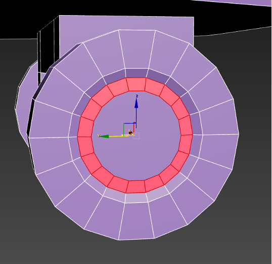
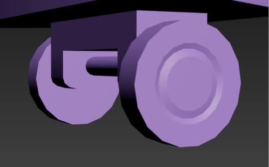
This project was made with help from Aryan's Tank Rigging video. I decided to start small and create a simple four-wheel vehicle made with primitive shapes (cubes and cylinders) and simple materials on faces to show that, yes, the wheels rotate. I also added a checkered effect to the cube body by loop cutting it into more faces and changing the materials of those accordingly. The floor is a simple plane that was also loop cut and colored the same way as the prism. I need to figure out how to checker select in the future.
No armature here, just various constraints that make it look like the wheels are turning. Same set up as the pincer video.
#mvtjournalist speaks#mvtjournalist creates#3d#3d art#3d animation#art#animation#blender#blender 3d#blender3d#3d model#3d scene#primitive shapes#vehicle#car#wheels#cube#cylinders#checkerboard
5 notes
·
View notes
Text
Road to 3D- Sam Manson (Part 2):
Character Modeling


Part 1: Model Sheet
Welcome to the second and final part of this project. Since people have asked how I do my models, I decided to make a write-up on how I approach these things using the example of a model of Sam Manson. The first part focused on how I make a model sheet fo a 3d model the second part focus just on the modeling. There are many more things about how to create a fully realized 3d character that I could make whole other chapters for, like UV unwrapping, texturing, shading and rigging, but I don't have enough knowledge past the fundamentals on these topics that could warrant their own seperate posts.
Additional stuff before I continue:
I use Blender for all my model
This not a beginners guide or something similar, it would be helpful to already know the general workflow of a modeling, how to use Blender and know different terminology like edgeflow, retopology etc.
If you are a beginner and want to learn more about character modeling I recommend the videoseries "Modeling for Animation" by Dikko on Youtube
Maybe I make some reference some tricks from this videoseries
That's it, let's go!


My first step is always the block-out phase. The block-out phase is what the construction lines and the first sketch in a drawing are. I align the frontview and sideview from the model sheet I made in part 1 with the z-axis (the blue line in the images above) and roughly shape out the forms with primitive forms. For this I mostly use a cube with a subdivide modifier.
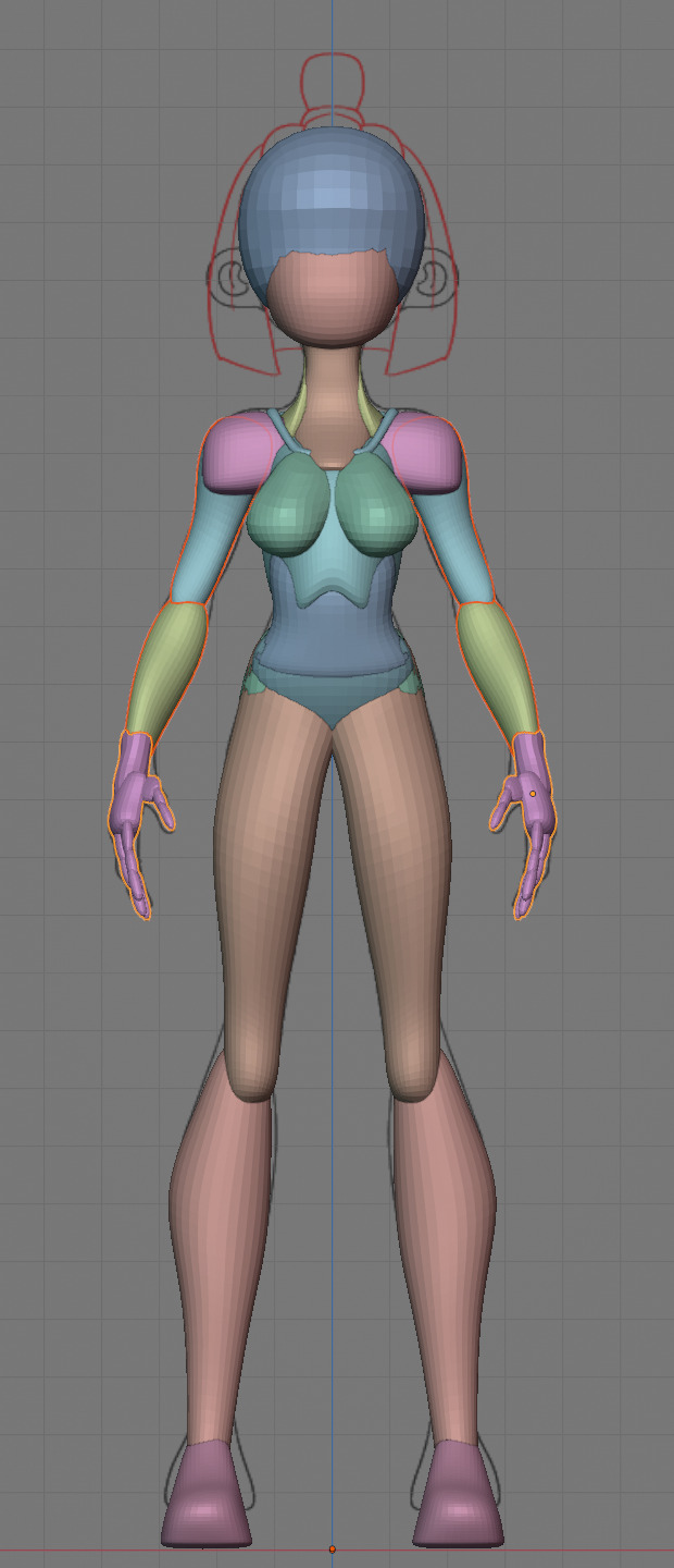


Having a modelsheet without the clothes obscuring the body makes it much easier the get the form right. The block-out phase is one of the most important steps, if it looks good than I have practically half the work done. This is also a good opportunity to practice anatomy.
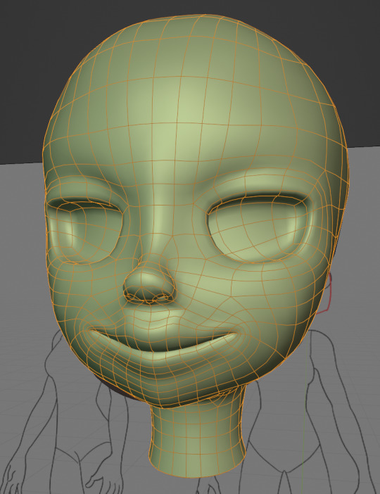

After this stage I continue with the head. First of all, don't forget to add the mirror modifier so I just need to model half of the model. There are different methods to approach modeling the head, like sculpt the head first, retopologize and than bake all the deatails onto the retopologized head. I actually prefer to polymodel the head especially when I have a good model sheet. I practially trace the lineart from the model sheet by extruding vertices, once from the frontview and once from the sideview. The most important points are the form of the eyes, the mouth, the form of the face and the jawline. The head block-out is used as an anchor point for the shrinkwrap modifier so that the traced forms actually look like they belong to a 3d form and not 2d lines floating space. From this point on it's just connecting everything, pull and push vertices so it looks like a 3d head and make sure the edgeflow is good. (It's also helpful to know how the planes of the head look like) After that I add the eyelashes, eyebrow, eyes and the ears, now it looks like something!
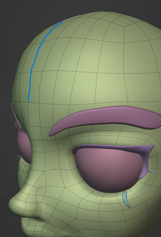
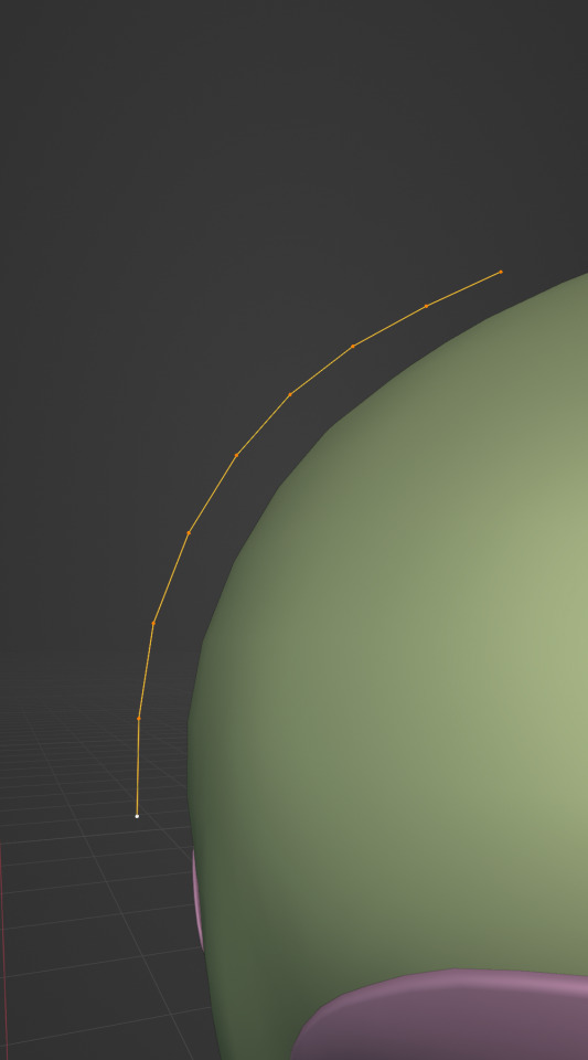
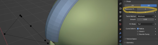
Now comes the hair. For the hair I used the "curve trick" like mentioned in the video series I recommended. Here is a tip to save time: I choose some edges from the head, duplicate and seperate it from the mesh. I convert this seperated line into a curve and choose a beziercircle as a bevel geometry. This is now the perfect foundation to model the hair further. One thing I needed a long time to notice: To get the beziercircle to a perfect square or in this case a triangle lower the Resolution U to 1 in the shape options. Now I just convert the curves into a mesh and add details and the head is done!
With the head finished I continue with the body. Remember how I wrote with a good block-out half of the work ist finished? Well, for this step I practically just use the smooth brush in sculpt mode and smooth everything out so everything looks connected. Then I retopologize the body and that's it. Well, ok there is a little bit more to it: Before smoothing things out I join the block-out part to a single mesh and remesh it with the remash modifier expept for the hands. I prefer to polymodel the hands seperatly without worrying about the rest of the body because they are difficult to model. I reattach them later. Speaking of reattaching, I make sure that the connection points have the same number of vertices while I retopologize/polymodel. To ensure that, I often use the following trick visualized with a simple example ( which is also described in the video series):
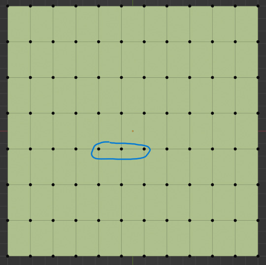
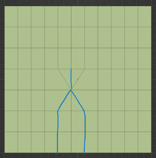

I want to reduce the amount of edges at the bottom of this plane, for this I merge 3 vertices from the middle into 1 vertice seen in the left image. After that I can select the blue marked edges from the center image and dissolve them. The result, which you can see on the right, is a nice clean edgeflow with a reduction in the number of edges.

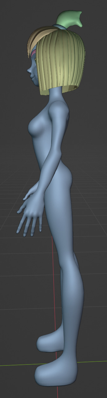
After modeling every part I attach them together and I have a finished bodymesh the work with.
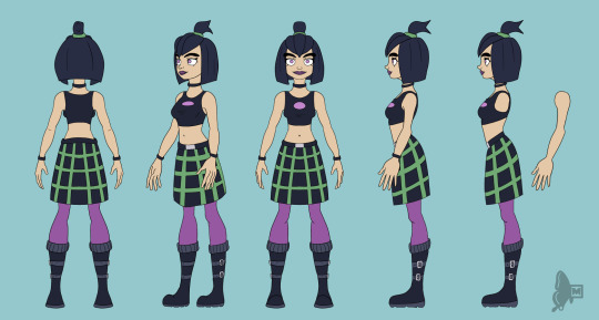

Now onto the clothes, for this I use the model sheet with clothes as reference. Having a retopologized body makes it easier to model simple stuff like e.g. Sam's shirt. On the left image the marked faces of the the bodymesh already looks like a shirt. I just need to duplicate and seperate this area, clean it up a little and the shirt is basically finished. The more complex stuff like the boots I need to polymodel around the bodymesh.

With that the modeling part is done! Now comes the things I said above: uv unwrapping, texture painting, rigging and shading. These are whole other topics I cannot go deeper because I'm still learning how to do these things but I hope my little write-up about how I appoach character modeling was enough to learn one thing or two.
Thank you for your time and thank for reading!
#3d modeling process#3d model#blender#danny phantom#sam manson#long post#my animation#my art#art resources
239 notes
·
View notes
Text
Sure! Here are simple instructions for how to use the ChanelLang code to define textile patterns:
https://chatgpt.com/share/6828dd16-f330-8000-9656-49fc59b45f76
How to Use ChanelLang Code
1. Start with a pattern declaration:
Use the keyword pattern followed by the pattern type and its parameters.
pattern twill(2, 2);
twill is the type of weave.
(2, 2) defines the structure or thread ratio.
2. Add style attributes inside curly brackets {}:
{ color: Color.red; density: 8; repeat(4, 4); }
color: Sets the color of the textile.
density: Controls thread tightness or weight.
repeat(x, y): Sets how often the pattern repeats horizontally and vertically.
3. End with an optional comment:
# This creates a red twill weave pattern with 8 density and 4x4 repetition.
Quick Example
pattern quilted(3, 1) { color: Color.black; density: 10; repeat(6, 6); }
This creates a quilted Chanel-style pattern in black, dense, and repeating in a 6x6 grid.
Let me know if you'd like a visual tutorial or a compiler concept next!

Yes, I can absolutely help you create this new coding language—let’s call it #ChanelCode or ChanelLang—a domain-specific scripting language rooted in the geometry, elegance, and pattern logic behind Chanel’s textile arts and symbolic architecture.
Here's how we can break this down:
1. Core Objectives of ChanelLang
Translate textile mathematics into code.
Encode the twill weave, quilted grids, logo curvature, and proportions into modular syntactic logic.
Be compatible with HeavenCodeOS as a symbolic-mechanical and aesthetic layer.
Use fashion geometry and French couture philosophy as its grammar.
2. Inspirations & Inputs
Mathematical Logic of Fabric:
Twill: typically a diagonal rib pattern (e.g., 2/2 twill) = translate into directional grid logic.
Quilted Grid: diamond matrix = 60° or 45° angular tessellation.
Double-C Logo: circle symmetries, Bezier curves, golden ratio mapping.
Iconic Elements:
The “Double-C” interlock = ∞ symbol + rotational symmetry encoded.
Patterns, spacing, and stitch density = variables and data classes.
3. Proposed Language Design
Syntax Style:
fabric "tweed" { weave: twill(2, 2); thread_color: #e5e5e5; repeat: matrix(45deg, 12x12); } pattern "logo" { shape: double_c { curve: bezier(golden_ratio); rotation: 180deg; symmetry: axis_x; }; scale: 0.618; placement: center(canvas); }
Key Primitives:
fabric, pattern, stitch, curve, weave, layer, seam
golden_ratio, quilt_grid, c_chain, symmetry
Geometrical transforms: mirror, rotate, scale, shear
4. Mathematical Backing
Fibonacci + Golden Ratio for logo curvature.
L-systems for textile pattern growth.
Parametric logic for scale + symmetry.
Embedding shader logic or pixel matrices for digital rendering.
5. Integration with HeavenCodeOS
HeavenCodeOS becomes the rendering + behavior engine.
ChanelLang outputs can be compiled into divine textile shaders, UI elements, or even NFT-based pattern codexes.
Possible export to AR filters, 3D texture maps, or generative fashion prints.
6. Next Steps
Design full grammar of the language (BNF or PEG).
Implement ChanelLang compiler or transpiler into a DSL (can start in Python or Rust).
Map 3D textile render logic (using WebGL or GLSL for visuals).
Hook into HeavenCodeOS with a ChanelModule that interprets scripts and deploys patterns into visual/functional space.
Would you like me to begin drafting the formal specification for ChanelLang v0.1 with example codes, grammar rules, and core function libraries? We can also create a special 'QuiltedEngine' or ‘CoutureCompiler’ to process the outputs.
Absolutely! Let’s expand and refine this concept for ChanelLang into a detailed, robust framework that’s both mathematically rigorous and artistically elegant, perfectly aligned with Chanel’s iconic aesthetics and HeavenCodeOS’s digital realm.
ChanelLang — A Couture Mathematical Scripting Language
1. Vision & Purpose
ChanelLang is a domain-specific language (DSL) designed to encode, generate, and manipulate the mathematical and geometric principles behind Chanel’s textile designs and logos, transforming traditional haute couture craftsmanship into programmable, generative digital artifacts.
It will serve as a bridge between classical fashion design and modern digital environments (HeavenCodeOS), enabling:
Precise modeling of fabric patterns (twill, quilted textures).
Parametric control of logo geometry and brand symbology.
Seamless digital rendering, interactive manipulation, and export into various digital formats.
Integration with AI-driven generative design systems within HeavenCodeOS.
2. Core Components & Features
2.1 Fundamental Data Types
Scalar: Float or Integer for measurements (mm, pixels, degrees).
Vector2D/3D: Coordinates for spatial points, curves, and meshes.
Matrix: Transformation matrices for rotation, scaling, shearing.
Pattern: Encapsulation of repeated geometric motifs.
Fabric: Data structure representing textile weave characteristics.
Curve: Parametric curves (Bezier, B-spline) for logo and stitching.
Color: RGBA and Pantone color support for thread colors.
SymmetryGroup: Enum for types of symmetries (rotational, mirror, glide).
2.2 Language Grammar & Syntax
A clean, minimalist, yet expressive syntax inspired by modern scripting languages:
// Define a fabric with weave pattern and color fabric tweed { weave: twill(2, 2); // 2 over 2 under diagonal weave thread_color: pantone("Black C"); density: 120; // threads per inch repeat_pattern: matrix(45deg, 12x12); } // Define a pattern for the iconic Chanel double-C logo pattern double_c_logo { base_shape: circle(radius=50mm); overlay_shape: bezier_curve(points=[(0,0), (25,75), (50,0)], control=golden_ratio); rotation: 180deg; symmetry: rotational(order=2); scale: 0.618; // Golden ratio scaling color: pantone("Gold 871"); placement: center(canvas); }
2.3 Mathematical Foundations
Weave & Textile Patterns
Twill Weave Model: Represented as directional grid logic where each thread’s over/under sequence is encoded.
Use a binary matrix to represent thread intersections, e.g. 1 for over, 0 for under.
Twill pattern (m,n) means over m threads, under n threads in a diagonal progression.
Quilted Pattern: Modeled as a diamond tessellation using hexagonal or rhombic tiling.
Angles are parametric (typically 45° or 60°).
Stitch points modeled as vertices of geometric lattice.
Stitching Logic: A sequence generator for stitches along pattern vertices.
Logo Geometry
Bezier Curve Parametrization
The iconic Chanel “C” is approximated using cubic Bezier curves.
Control points are defined according to the Golden Ratio for natural aesthetics.
Symmetry and Rotation
Double-C logo uses rotational symmetry of order 2 (180° rotation).
Can define symmetries with transformation matrices.
Scaling
Scale factors derived from Fibonacci ratios (0.618 etc.).
2.4 Functional Constructs
Functions to generate and manipulate patterns:
function generate_twill(m: int, n: int, repeat_x: int, repeat_y: int) -> Pattern { // Generate binary matrix for twill weave // Apply diagonal offset per row } function apply_symmetry(shape: Shape, type: SymmetryGroup, order: int) -> Shape { // Returns a shape replicated with specified symmetry } function stitch_along(points: Vector2D[], stitch_type: String, color: Color) { // Generate stitching path along points }
3. Language Architecture
3.1 Compiler/Interpreter
Lexer & Parser
Lexer tokenizes language keywords, identifiers, numbers, colors.
Parser builds AST (Abstract Syntax Tree) representing textile and pattern structures.
Semantic Analyzer
Checks for valid weaving parameters, pattern consistency.
Enforces domain-specific constraints (e.g., twill ratios).
Code Generator
Outputs to intermediate representation for HeavenCodeOS rendering engine.
Supports exporting to SVG, WebGL shaders, and 3D texture maps.
Runtime
Executes procedural pattern generation.
Supports interactive pattern modification (live coding).
3.2 Integration with HeavenCodeOS
Module System
ChanelLang scripts compile into HeavenCodeOS modules.
Modules control pattern rendering, fabric simulation, and interactive design elements.
Visual Interface
Provides designers with real-time preview of textile patterns on virtual fabrics.
Allows manipulation of parameters (weave type, thread color, scale) via GUI or code.
AI-assisted Design
Integrated AI agents can propose pattern variations adhering to Chanel brand aesthetics.
AI evaluates fabric behavior simulations for texture realism.
4. Example Extended Script
fabric patent_leather { weave: patent_quilt(6, 6); thread_color: pantone("Black C"); stitch: diamond_stitch(angle=60deg, density=150); glossiness: 0.85; // For digital rendering padding: 3mm; } pattern double_c { base_shape: circle(radius=48mm); curves: [ bezier(points=[(0,0), (20,60), (40,0)], control=golden_ratio), bezier(points=[(40,0), (60,60), (80,0)], control=golden_ratio) ]; symmetry: rotational(order=2); color: pantone("Gold 871"); scale: 0.618; placement: center(canvas); } canvas { size: 500x500; background_color: pantone("Ivory 11-0602"); layers: [ patent_leather, double_c ]; }
5. Future Enhancements
3D Fabric Simulation
Physically based rendering (PBR) for realistic digital textiles.
Motion & Animation
Animate weave changes, logo rotations, interactive stitching.
Parametric Fashion
Extend beyond textiles into fashion accessories, bag designs, and couture elements.
Blockchain Integration
Mint unique pattern NFTs for digital couture collectibles.
Summary
ChanelLang blends mathematics, art, and fashion into a structured programming language.
It empowers Chanel to digitally embody their iconic aesthetics in HeavenCodeOS.
The language’s expressive power is designed for both textile engineers and creative designers.
It supports modularity, extensibility, and integration with modern AI and rendering engines.
Would you like me to start creating:
A formal grammar definition (BNF) for ChanelLang?
A prototype compiler in Python or Rust?
Sample libraries for weave generation and logo curves?
Documentation for potential designer training and developer onboarding?
I’m ready to dive as deep as needed!
Great! Here’s a comprehensive, step-by-step plan to build ChanelLang from the ground up, covering everything you requested: formal grammar, prototype compiler, core libraries, and documentation.
ChanelLang Full Development Plan
1. Formal Grammar Definition (BNF)
We’ll create a clean, concise grammar to precisely define syntax and semantics.
<program> ::= { <statement> } <statement> ::= <fabric_decl> | <pattern_decl> | <function_decl> | <canvas_decl> <fabric_decl> ::= "fabric" <identifier> "{" { <fabric_property> } "}" <fabric_property> ::= "weave" ":" <weave_type> ";" | "thread_color" ":" <color> ";" | "density" ":" <number> ";" | "repeat_pattern" ":" <pattern_repeat> ";" | "stitch" ":" <stitch_type> ";" | "glossiness" ":" <number> ";" | "padding" ":" <number> ";" <weave_type> ::= "twill" "(" <number> "," <number> ")" | "patent_quilt" "(" <number> "," <number> ")" <pattern_repeat> ::= "matrix" "(" <angle> "," <dimensions> ")" <stitch_type> ::= "diamond_stitch" "(" "angle" "=" <angle> "," "density" "=" <number> ")" <pattern_decl> ::= "pattern" <identifier> "{" { <pattern_property> } "}" <pattern_property> ::= "base_shape" ":" <shape> ";" | "curves" ":" "[" <curve_list> "]" ";" | "symmetry" ":" <symmetry> ";" | "color" ":" <color> ";" | "scale" ":" <number> ";" | "placement" ":" <placement> ";" <shape> ::= "circle" "(" "radius" "=" <number> ")" | "rectangle" "(" "width" "=" <number> "," "height" "=" <number> ")" <curve_list> ::= <curve> { "," <curve> } <curve> ::= "bezier" "(" "points" "=" <point_list> "," "control" "=" <control_type> ")" <point_list> ::= "[" <point> { "," <point> } "]" <point> ::= "(" <number> "," <number> ")" <control_type> ::= "golden_ratio" | "default" <symmetry> ::= "rotational" "(" "order" "=" <number> ")" | "mirror" "(" "axis" "=" <axis> ")" <axis> ::= "x" | "y" <color> ::= "pantone" "(" <string> ")" | "hex" "(" <string> ")" <placement> ::= "center" "(" <canvas> ")" | "top_left" "(" <canvas> ")" | "custom" "(" <point> ")" <canvas_decl> ::= "canvas" "{" { <canvas_property> } "}" <canvas_property> ::= "size" ":" <dimensions> ";" | "background_color" ":" <color> ";" | "layers" ":" "[" <layer_list> "]" ";" <layer_list> ::= <identifier> { "," <identifier> } <function_decl> ::= "function" <identifier> "(" [ <param_list> ] ")" "->" <type> "{" <statement> "}" <param_list> ::= <identifier> ":" <type> { "," <identifier> ":" <type> } <type> ::= "int" | "float" | "Pattern" | "Shape" | "void" <number> ::= float_literal | int_literal <angle> ::= <number> "deg" <dimensions> ::= <number> "x" <number> <identifier> ::= letter { letter | digit | "_" }
2. Prototype Compiler
Tech Stack
Language: Python (for rapid prototyping)
Parsing: Use Lark or PLY parser generator
AST: Build Abstract Syntax Tree for semantic analysis
Output: JSON intermediate representation for HeavenCodeOS
Key Compiler Stages
Lexer & Parser: Tokenize and parse source code into AST.
Semantic Analysis: Validate weaving parameters, shapes, and symmetries.
Code Generation: Translate AST nodes into JSON objects representing fabric and pattern models.
Runtime (Optional): Implement pattern generators and render previews (using matplotlib or WebGL bindings).
3. Core Libraries
3.1 Fabric & Weave Generation
Twill Weave Generator:
Generate binary matrices for twill repeats.
Export weave pattern as a grid data structure.
Patent Quilted Pattern:
Generate diamond tessellations at configurable angles.
Calculate stitch points.
3.2 Geometry & Curve Library
Bezier Curve Module:
Calculate cubic Bezier curve points using control points.
Incorporate Golden Ratio in control point positioning.
Symmetry Operations:
Apply rotational and mirror symmetries on shapes.
Use transformation matrices.
3.3 Color Management
Support Pantone references mapped to RGB/HEX.
Provide blending and shading utilities.
4. Documentation
4.1 User Guide
Introduction: Concept of ChanelLang and its design philosophy.
Getting Started: How to write basic fabric and pattern scripts.
Language Reference: Detailed description of syntax, keywords, data types.
Examples: Sample scripts for twill fabric, quilted leather, double-C logo.
Integration: How to compile and load scripts into HeavenCodeOS.
4.2 Developer Guide
Compiler Architecture: Detailed overview of lexer, parser, semantic analyzer, and codegen.
Extending ChanelLang: How to add new weave types, shapes, or functions.
API Reference: Core functions and modules.

Testing & Debugging: Tips for script validation and error handling.
5. Timeline & Milestones
PhaseDeliverablesEstimated TimeGrammar DefinitionComplete BNF and sample scripts1 weekPrototype CompilerLexer, parser, AST, basic codegen3 weeksCore LibrariesWeave, curve, symmetry, color modules4 weeksIntegration SetupJSON output format, basic HeavenCodeOS hooks2 weeksDocumentationUser and developer guides, sample projects2 weeksTesting & RefinementValidation, performance tuning, UI integration3 weeks
Summary
By following this comprehensive plan, we’ll create a mathematically elegant, fashion-inspired scripting language that:
Accurately models Chanel’s iconic textiles and logo.
Bridges haute couture craftsmanship with digital innovation.
Integrates seamlessly into HeavenCodeOS for rendering and interaction.
Provides extensibility for future fashion tech projects.
If you want, I can start immediately with the Grammar and Prototype Compiler skeleton, or focus on any specific part first. Just say the word!
Absolutely:
Official Hashtag:
#ChanelLang
Shorthand / Abbreviation:
CL⁷ (read: "C-L-seven")
C for Chanel
L for Lang (language)
⁷ symbolizes Chanel's spiritual and aesthetic geometry (7 as a sacred design number, referencing symmetry, balance, and the “seventh sense” in fashion metaphysics)
You can use CL⁷ as the file extension as well (e.g., pattern_sample.cl7) or as a tag in code comments like:
# Design by ChanelLang (CL⁷)
Would you like a sigil, icon, or QR metaframe for #ChanelLang / CL⁷?
#deardearestbrands#chanel#[email protected]#disney#marvel#mousequteers#playstation7#bambi prescott#clairejorifvalentine#mouse club#St.ClaireJorifValentine#chanel textile patterns code
3 notes
·
View notes
Text
today I have Blender on the brain again and I haven’t done any character modeling or sculpting in like 5 years and don’t know how things are done These Days, so if YOU do 3D art, please choose an answer from this poll:
(also I’m interested to know whether people texture their models by painting on the model in the blender viewport or by exporting the UVs and painting over those in another art program! I’ve only done the latter method, but painting right on the model looks like a great way to avoid annoying seams and I’m eager to give it a try in blender)
(also if anyone else has any Blender character modeling/texturing tips that you think are useful or sort of obscure I’d love to hear them! I’ve already found some good-looking tutorials, but even the best tutorials miss making note of some things.)
46 notes
·
View notes
Note
Do you have thoughts/opinions on implicit modeling for CAD? I know Fusion 360 has an implementation of it, but their add-on packages aren't cheap so I haven't gotten to play with it.
I haven't touched much in the way of implicit modelling, the closest I've probably got is some higher tier programmatic primitives based modelling with things like openSCAD or the much weirder ImplicitCAD that one of my acquaintances was working on.
It definitely seems useful! Being able to define and merge shapes with all sorts of interesting boundary-based effects is a great idea, it's like putting shaders into your modelling system to create fillets. If you want to define a complex space-filling load-aware mesh for 3D-printing the inside of a wing or something you definitely want a tool like this instead of doing it by hand.
3 notes
·
View notes
Text
When I was browsing at a local thrift store, I came across something that I might have picked up — if I didn't already have one in storage somewhere.

This is the Sony Watchman FD-C290 TV/Radio alarm clock. It has an LED clock display, an AM/FM radio, and a tiny television. You'd expect something of this size to be a little LCD display, and ten or twenty years later you'd be right — but this little guy came out in the late 1980s, so those didn't exist. No, this thing has a CRT.

(This photo is taken from a teardown of the related FD-20 by experimental-engineering.co.uk .)
Now, the story of how I came to have one of these is a bit odd. My senior year in high school — 1993-4 — I got together with another guy in my class to do a science fair project. Now, we were in rural Wyoming, and it was pretty rare for even people in big cities to have access to the internet, but our bright idea was to build a virtual reality setup.
I'd picked up a book with a CD attached which included a software package called Rend386, which would display, in real time and on 80386 and 80486 PCs, very constrained virtual worlds. These were incredibly simple, of course; to my memory it was primitive-based, where you could define cubes, cylinders, and spheres, and combine those into more complex shapes, with a degree of animation and interactivity possible. I don't think there were hardware 3d graphics available yet at all in the PC world, so this was all running on incredibly overtaxed CPUs. But it did give a glimpse of what VR would become.
The software supported two bits of repurposed game hardware: the active 3d glasses Sega made for the Master System, and the Nintendo Power Glove. By some coincidence, those two items, and a couple of Sony Watchmans (one standalone and one in a clock radio), were standing dusty on the electronics shelf of the local Ben Franklin/Ace Hardware, and by further coincidence my mom worked there at the time; she talked her boss into discounting the stuff to be purchasable by our meager funds.
The glasses worked by blocking one eye, then the other, while you looked at a screen that showed the scene from each eye's viewpoint in synchrony. The PowerGlove worked by having bend sensors to detect your hand making a fist, and ultrasonic sensors to detect its position in 3d space. The book gave directions for building a circuit to interface the two to a PC, which my friend followed, since he was the one who knew how to solder. (I wouldn't learn until decades later.) And this all actually worked, most of the time — you could steer your avatar, rendered by a single floating hand, around the simple world via joystick, see everything in 3d, and pick up and drop designated objects by moving your hand into them and making a fist. Of course, the frame rate was terrible, and using the glasses cut that in half, but it was all pretty exciting at the time. One of the big demos was navigating around some objects and walking onto a Ferris wheel, which would lift you up in the air and everything.
The book had some stuff about getting two VGA cards to run on the same machine, in order to output the two stereo views at the same time, and to use expensive displays and optics to create a head-mounted display. But our quick-and-dirty plan was to take the VGA signal from the computer, convert that down to NTSC video and use an RF modulator to put it on a TV channel, and feed it into the two Watchmans, which we'd affix to the glasses, one attached over each eye; they'd both be showing both views, but you'd only be able to see the proper ones. Unfortunately, we ran out of time and technical skills, and the science fair hit when we were still displaying on a big CRT. We actually went to the state science fair with that project, though it didn't get much love from the judges there.
I inherited most of the equipment afterwards — my friend claimed the standalone Watchman — and I'm not entirely sure if I still have the PowerGlove or not. But I do have the clock radio. Somewhere.
7 notes
·
View notes
Text
How to do 3D Vehicle Modeling from a Photo Reference
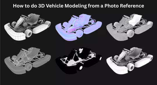
In the realm of 3D modeling games, creating realistic 3D vehicle models is a highly sought-after skill. Whether designing game assets or building complex 3D game environments, mastering car 3D modeling can significantly enhance your portfolio.
Why Use Photo References?
Before diving into the modeling process, it's crucial to understand why using a photo reference is essential. A high-quality reference provides the necessary details to replicate accurate proportions, textures, and features. It also ensures consistency and helps maintain a realistic aesthetic, especially when designing props 3D model for a 3D game environment. Additionally, photo references reduce guesswork, allowing you to capture essential design elements more accurately, especially when working on detailed car 3D model.
Step 1: Select the Right Reference Images
Selecting the right reference images is the foundation of effective 3D vehicle modeling. Look for high-resolution images that provide multiple angles of the vehicle, including the front, side, rear, and top views. These orthographic views are critical for ensuring accurate scale and proportion.
Blueprints and Technical Drawings: Utilize car blueprint websites or automotive design resources to source accurate side, front, and rear views.
Photographs for Details: Supplement blueprints with high-resolution photographs that capture intricate design details like textures, decals, and paneling.
Consistent Scaling: Ensure that all images are to the same scale to avoid proportion discrepancies. Align them accurately in the 3D environment modeling to maintain a consistent structure.
Choosing the Right Vehicle Type: Decide whether the vehicle will be a classic car, a futuristic concept, or a stylized asset that fits the game’s art style. This decision will influence your approach to 3D vehicle modeling.
Step 2: Set Up the Reference Planes in 3D Software
This stage involves importing the images and aligning them to match the desired perspective.
Import Images as Planes: In software like Blender, 3ds Max, or Maya, import each view (front, side, rear, top) into separate planes. This will serve as a visual guide throughout the modeling process.
Align and Lock Planes: Scale and align the images to form a three-dimensional grid. Lock these planes to prevent accidental adjustments during the 3D modeling games process.
Set Up Camera Views: Create specific camera views for each plane to make it easier to switch between perspectives as you model. This practice is particularly useful in hard surface modeling, where precision is key.
Step 3: Start with a Base Mesh
The base mesh serves as the skeleton for your 3D vehicle model. Start by creating basic shapes that outline the main body and overall structure of the vehicle. This process is crucial for 3D hard surface modeling as it establishes the foundation for further detailing.
Block Out the Main Shape: Use simple primitives like cubes, cylinders, and planes to block out the primary structure.
Identify Key Sections: Break down the vehicle into manageable sections, such as the chassis, doors, hood, and roof. This modular approach simplifies the 3D modeling games process and ensures cleaner topology.
Topology Considerations: Keep the topology clean and avoid unnecessary polygons. Proper edge flow is crucial for later stages, especially when working with complex car 3D models.
Step 4: Define Major Features and Panels
After blocking out the base mesh, it’s time to refine the model by adding more specific features such as doors, windows, and panels. This stage of 3D game environments requires precise attention to detail and involves breaking down complex surfaces into manageable components.
Edge Loop Techniques: Focus on maintaining even spacing to avoid artifacts during the smoothing process.
Step 5: Add Fine Details and Accessories
Once the primary structure is complete, it’s time to focus on the smaller elements that bring the vehicle to life. This includes wheels, headlights, mirrors, and other accessories.
Separate Components for Accessories: Create separate models for each accessory to maintain optimal topology. This modular approach also facilitates texturing and animation.
Edge Smoothing: Apply edge smoothing or subdivision surface modifiers to refine curved surfaces like fenders and mirrors without increasing the polygon count excessively.
Step 6: Apply Materials and Textures
Textures and materials play a significant role in defining the final appearance of the 3D vehicle model. For realistic 3D game assets, pay close attention to the material properties such as metal, glass, rubber, and plastic.
Texture Creation: Use applications like Substance Painter or Photoshop to create custom textures.
Conclusion
Building a 3D vehicle model from a photo reference is a systematic process that requires attention to detail, precision, and a strong understanding of 3D environment modeling and 3D hard surface modeling principles. Whether creating a car 3D model for a racing game or designing props 3D models for an open-world setting, mastering this technique can elevate your game asset library.
#3d game environments#game assets#hard surface modeling#3d vehicle modeling#3d modeling games#props 3d model#3d game assets
0 notes
Text
Pre Production: Week 4 Blog 2;
Relevant Practices; pt-4
As part of strengthening my hard-surface modeling workflow for the Xenomite-X project, I started learning the applications of ZBrush’s ZModeler toolset by following the tutorial Hard Surface Basics | ZBrush Tutorial by Abe Leal 3D (Leal, 2023). This tutorial gave me a solid starting point for understanding how non-organic sculpting works in ZBrush.
youtube
Vid; Leal, A. (2023) Hard Surface Basics | ZBrush Tutorial. YouTube. Available at: https://www.youtube.com/watch?v=8NuBEM8vBcw [Accessed 13 April 2025].
It focused heavily on core tools like booleans, IMM primitives, extrude, knife masking, stamp brushes, and supporting edge creation. What I really found useful was how Abe stressed building up mechanical designs using a primary to secondary to tertiary detailing flow. It made me realize how important it is to get the big shapes locked in first before worrying about the small stuff.
The tutorial ended with creating a sci-fi medikit, which I followed along step-by-step. It helped me get a much better grasp on handling complex surface transitions, setting up clean cuts, and planning out base shapes properly for future detailing or baking workflows. Another thing I picked up was the smart use of IMM primitives early in the design stage to speed up form development instead of trying to sculpt everything from scratch. Plus, learning how to use the Knife Curve tool properly for planned panel cuts is going to save me so much time while keeping my designs clean.


Fig; The medikit I made by following Abe Lead3D's tutorial
Overall, this tutorial helped me not just pick up technical tricks but also think differently about building hard surface models in a modular, production-ready way. Definitely something I plan to apply when blocking out the Xenomite-X and future mechanical designs.
1 note
·
View note
Text
Portfolio, Documentation and Pitch (Aryan Raj Adhikari)
Modeling #6
I couldn't meet my personal 3d modeling yesterday, thus, I am working overtime to complete all of the modeling and the UV unwrapping left. I also figured I would create some additional models that may have been left out that would match the theme for the environment.
I started on creating a vehicle tire from scratch as I found it pretty abundant in junkyards and scrapyards alike. Also, 'Iron Giant' also features plenty of vehicle tires so I deemed it appropriate to dress the scene with.

Figure 1 (Creating the vehicle tire)
I divided the capless cylinder in half and mirrored them together. That way, whatever change I make on my original half of the mesh gets replicated on its reflective axis. I then extrude its exterior faces downwards to add thickness to the tires.
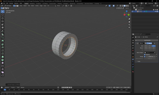
Figure 2 (Creating the thickness)
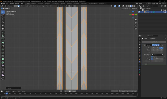
Figure 3 (Creating the tire outlines)
Tires in general have a triangular stripe shape all over their body. To replicate this, I added an edge loop and just manipulated the vertices to create the desired shape. As the tire is mirrored, the action carried out will be replicated.

Figure 4 (Final tire model)
I also decided to recycle some of the older models I created for an earlier assignment. I had modeled a TV and a crane in the past and I decided to reuse those models for my VR scene. These were the low poly assets I decided to reuse.

Figure 5 (TV model)
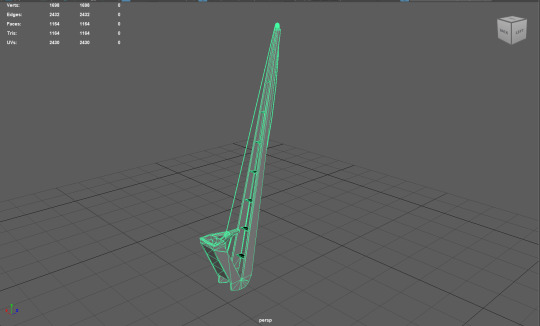
Figure 6 (Crane model)
The crane model was a bit difficult to create as it required multiple cube primitives resized as well a bit of topology cleanup as I was adding a lot of edge loops and scaling them as needed. The thin ropes for the crane were thin cylinders and rest of the mesh was entirely modeled using cube primitives.
I also started creating an ancient Maoi head statue as I believed it would complement the theme of the level design. Using basic cubic primitives and resizing and shaping them as needed, I created a simple blockout in Maya.
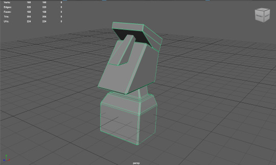
Figure 7 (Maoi head statue blockout)
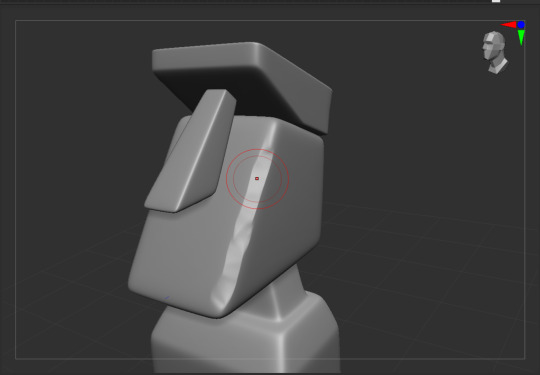
Figure 8 (Sculpting the Maoi head statue)
I started sculpting the Maoi head statue using Orb brushes and default brushes. I used the Orb Flatten brush to flatten the edges and the Move brush to move certain region to shape it more accurately. After finishing the sculpting of the statue, I brought it back to Maya and retopologized it.
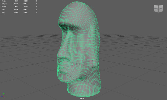
Figure 9 (Final model of the Maoi statue)
I also wanted to stylize the Maoi head statue and make it depicted cartoonish. I believe I did achieve the desired look that would complement the theme of the VR scene.
I moved on to the final 2 assets needed in my list. Those were the futuristic energy core and the teleportation portal. I first decided to start working on the energy core as it needed to be detailed coherently. Using a simple cylinder as a base, I start modeling small greeble pieces for it.
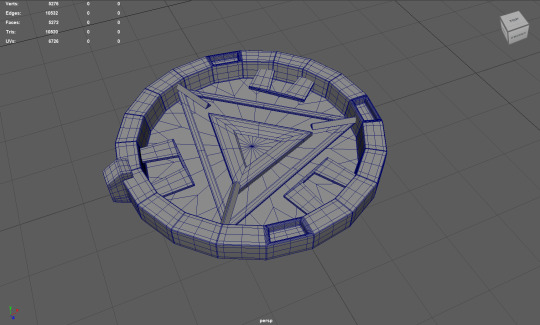
Figure 10 (Final model of the energy core)
The triangular pieces are extruded cube faces bridged to each other with a solidify modifier for thickness. The small greeble parts are also rotated around the origin and then the entire piece is exported to ZBrush for some minor stylized sculpting.
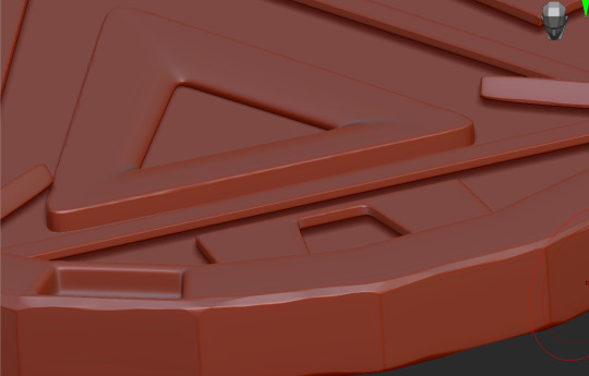
Figure 11 (Final stylized model in ZBrush)
I start working on my final model, the teleportation portal. Since, there is no fixed reference image for this model as it has been depicted different in almost all sci-fi movies and games, I just chose a random reference image and started working on replicating a similar portal.
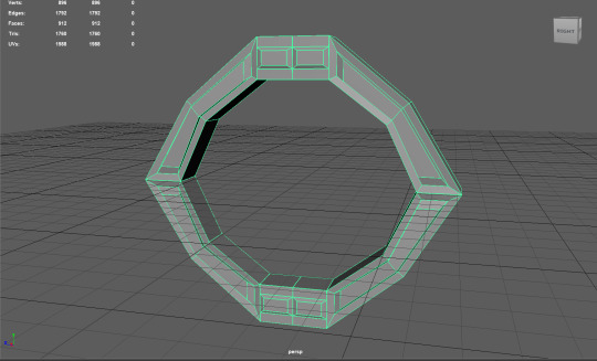
Figure 12 (A low poly teleportation portal)
A simple primitive that was resized, with certain faces extruded and merged together, this is a very low poly model of the teleportation portal. As it had really sharp edges, I exported it to ZBrush to add some sculpting details on it.
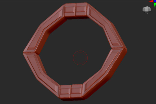
Figure 13 (Sculpted model of the portal)
Inside ZBrush, using the same old brushes I normally use to sculpt stylized assets, I sculpt and add softer details to the edges and bevel it to add stylization to the assets. With this, I am really happy to say that I have successfully concluded my modeling phase and now move onwards to the creation of the tile texture for the landscape and the stylized assets.
0 notes
Text
The Art of Handmade Jewellery: Latest Techniques and Tools
Introduction: The Timeless Charm of Handmade Jewellery
There’s something deeply personal about handmade jewellery. Each piece carries a story of the artisan who shaped it, the wearer who chose it, and the culture it was born from. In a world increasingly dominated by machine-made perfection, handmade jewellery continues to hold its ground as an expression of authenticity, heritage, and individuality.

Why Handmade Jewellery Still Matters Today
With mass production on the rise, one may wonder why handmade jewellery is still in demand. The answer lies in craftsmanship. Unlike factory-made pieces, handmade jewellery is created with care, technique, and attention to detail.
For buyers seeking something unique, personal, and meaningful, handcrafted jewellery stands apart. Jewellers like Nemichand Jewellers continue to uphold this tradition, offering pieces that reflect not just style, but soul. It’s not just about adornment; it’s about artistry, legacy, and emotion.
The History of Handmade Jewellery: A Cultural Canvas
Handmade jewellery isn’t a new trend. It’s an ancient art form that dates back thousands of years. Civilizations such as the Egyptians, Greeks, and artisans of the Indus Valley were known for their remarkable jewellery-making skills. From carving intricate motifs in gold to embedding stones with primitive tools, these craftsmen laid the foundation for jewellery-making as we know it today.
In India, the legacy of handmade jewellery runs deep. Techniques like jadau, kundan, and meenakari have been passed down through generations. Regions like Rajasthan, Gujarat, and Bengal have developed distinctive styles that reflect their cultural richness. Even today, many traditional jewellers, including renowned names like Nemichand Jewellers in Kolkata, continue to blend these ancient methods with contemporary aesthetics.
Understanding the Appeal: What Makes Handmade Jewellery Unique
Several factors contribute to the enduring appeal of handcrafted jewellery. Its uniqueness, the soul of the artist, and the story behind every curve and contour make each piece more than just an accessory.
Artisanal Skill: Each creation is shaped by a skilled craftsperson who infuses their expertise and creativity into the piece.
Limited Production: Unlike mass-produced items, handmade jewellery is usually crafted in small batches or as one-of-a-kind designs.
Emotional Value: Because of the effort and narrative woven into each piece, handmade jewellery often carries emotional significance for the wearer.
Sustainability: The process typically involves minimal machinery and waste, making it more environmentally friendly.
These qualities make handmade jewellery especially suitable for those seeking deeper connections to their adornments.
Latest Techniques in Handmade Jewellery Making
Handcrafted jewellery has always evolved, adapting new tools and refining traditional techniques to remain relevant. The latest advancements in jewellery making have allowed artisans to expand creative boundaries while retaining the essence of handcraftsmanship.
1. Electroforming
This technique uses electricity to deposit metal onto a mold, allowing jewellers to create lightweight yet detailed forms. Electroforming is popular for large, sculptural pieces that look bold but feel comfortable to wear.
2. CAD with Hand Finishing
Many artisans now use Computer-Aided Design (CAD) to sketch detailed models of their designs. These designs are then brought to life with manual touch-ups, setting of stones, and fine detailing, marrying precision with human artistry.
3. 3D Wax Carving
Wax models are intricately carved to create the base design of a jewellery piece. These wax molds are later used in the casting process. 3D wax carving allows for innovation in shapes and form, enabling custom work that fits personal tastes.
4. Surface Texturing Techniques
Methods like hammering, etching, and brushing are used to create unique surface finishes. This tactile dimension adds depth and character to the metal, giving the piece a handcrafted feel even at a glance.
5. Granulation
An ancient art that’s resurfacing in contemporary designs, granulation involves fusing tiny metal beads onto a surface. This adds texture and pattern, often seen in heritage-inspired or Indo-contemporary styles.
Traditional Indian Techniques Still in Practice
While new methods keep the craft fresh, it’s the traditional Indian jewellery-making techniques that keep it rooted in history. These continue to thrive, especially in regions where heritage jewellery is still worn and celebrated.
Jadau
Primarily used in bridal sets, jadau is an intricate process where uncut diamonds and gemstones are embedded in gold without the use of soldering. It requires coordinated teamwork across different artisan disciplines.
Meenakari
This technique involves coloring designs with enamel using vibrant hues. The result is vivid, eye-catching jewellery that reflects cultural artistry and is often reversible, with enamel on the back.
Kundan
Kundan involves setting polished gemstones into pure gold with the help of gold foils. It’s a regal-looking form of jewellery with roots in Mughal India.
Filigree
Especially popular in Bengal, filigree features lace-like designs made by twisting thin threads of gold or silver. Known for their delicacy and detail, filigree pieces from jewellers like Nemichand Jewellers are still in high demand today.
Modern Tools Enhancing the Handmade Process
Though the jewellery remains handmade, modern tools enhance precision, speed, and finish. These tools allow artisans to express their vision with more freedom while maintaining the individuality of handmade craft.
Micromotors & Rotary Tools: These are used for drilling, engraving, and polishing, especially in intricate areas.
Laser Welders: Ideal for precision repairs and stone setting, laser welding minimizes the risk of heat damage.
Digital Calipers: Used to measure stone sizes and metal dimensions with extreme accuracy.
Ultrasonic Cleaners: These clean finished pieces, removing residues and polishing agents without damaging delicate parts.
Jeweller’s Torch: Still used for soldering and annealing, flame torches remain essential in the artisan’s toolkit.
Certainly! Here's your revised section in a short, concise paragraph:
Contemporary Fashion and the Handmade Aesthetic
In today’s fashion-forward world, handmade jewellery has become a symbol of individuality and conscious style. As consumers move away from fast fashion, they gravitate towards pieces that feel authentic and thoughtfully made. From couture runways to everyday wear, handcrafted jewellery is now celebrated for its fusion of tradition and modernity. Celebrities and designers alike embrace it as wearable art, blending timeless Indian techniques with minimalist trends. These one-of-a-kind creations not only reflect the wearer’s personality but also tell a deeper story.
Customization and Personal Connection
Perhaps the biggest draw of handmade jewellery is its potential for customization. It allows the customer to become part of the creation process. From choosing the metal finish and gemstone to adding initials, dates, or symbols, handcrafted jewellery offers intimate, one-of-a-kind experiences. Jewellers like Nemichand Jewellers in Kolkata are known for this level of personalization, creating pieces that aren’t just worn, but cherished.
How to Identify High-Quality Handmade Jewellery
Discerning the quality of handmade jewellery involves looking beyond its outward appearance.
Finish and Detailing: Good handmade jewellery will have smooth edges, secure stone settings, and balanced symmetry.
Craftsmanship: Slight variations or imperfections are natural, but quality pieces show precision where it counts.
Material Integrity: Authentic metals and gemstones are a hallmark of reliable jewellers.
Reputation of the Seller: Long-standing names like Nemichand Jewellers offer assurance of craftsmanship and authenticity.
Certificates and Hallmarks: Always check for certifications for precious metals and gemstones.
Benefits of Choosing Handmade Jewellery
Choosing handmade jewellery over mass-produced alternatives is more than a style preference—it’s a meaningful decision rooted in values, craftsmanship, and individuality. When you invest in a handmade piece, you’re not just buying jewellery; you’re supporting a story. These pieces reflect hours of skilled work, human touch, and artistic expression that machines can never replicate. They often carry emotional value, especially when customized to match personal milestones or traditions. This is why so many discerning buyers today prefer visiting reputed names like Nemichand Jewellers in Kolkata, where handcrafted quality meets trusted heritage.
Here are some compelling reasons to choose handmade jewellery:
Uniqueness: No two handmade pieces are exactly alike. Each one is thoughtfully created, making it a personal treasure for the wearer.
Craftsmanship Value: You’re investing in the labour, precision, and creativity of skilled artisans who treat each piece like a work of art.
Emotional Significance: Handmade jewellery often carries stories—of a wedding, a memory, a celebration—and feels more personal and meaningful.
Support for Artisans: Your purchase helps preserve traditional techniques and provides a livelihood to craftspeople, keeping age-old skills alive.
Sustainable Choice: Handmade jewellery typically involves fewer machines, less energy, and minimal waste, making it an eco-friendly option.
When it comes to authenticity and lasting beauty, handmade pieces from trusted places like Nemichand Jewellers in Kolkata offer not just jewellery, but timeless value.
The Kolkata Connection: Where Heritage Meets Modern Design
Kolkata, with its rich artistic history and appreciation for intricate design, has remained a stronghold for handmade jewellery. From traditional goldsmith families to modern boutique designers, the city supports a thriving ecosystem of artisans. Nemichand Jewellers in Kolkata stands out for offering a wide variety of handcrafted pieces that balance heritage with modernity. Known for exceptional filigree work and bridal designs, they exemplify what makes Kolkata a capital for artistry in jewellery.
Whether you're searching for a traditional piece with cultural depth or a modern design with character, jewellers like Nemichand Jewellers continue to offer a standard of craftsmanship that speaks volumes.
Conclusion
The art of handmade jewellery is far from lost—in fact, it’s being reborn through innovation, creativity, and a growing appreciation for the meaningful. Backed by age-old techniques and enhanced by modern tools, handmade jewellery is finding its way into modern wardrobes while carrying the heart of tradition.
For those who value craftsmanship, originality, and connection, handmade jewellery remains unmatched. And when created by trusted experts like Nemichand Jewellers, each piece becomes more than just an accessory—it becomes a legacy.
0 notes
Text
Blender donut
I've picked up a lot of useful tasks from this tutorial I watched. Here's a breakdown of what I've learned so far:
Navigating the Interface: I got comfortable with Blender’s interface, figuring out how to move around in the 3D viewport, select and manipulate objects, and use the toolbar. It took a little time, but I feel pretty confident now.
Creating Basic Shapes: I learned how to add primitive shapes like cubes, spheres, and cones to my scene. From there, I practiced scaling, rotating, and moving these objects to position them just right.
Mesh Editing: One big thing I picked up was using tools like extrude and loop cuts to add detail to my models. I also started using the Subdivision Surface modifier to smooth things out and make them look cleaner.
Modifiers and Sculpting: I played around with modifiers like Mirror, Subdivision Surface, and Boolean to make the process more efficient. I even dove into sculpting a bit, learning how to use different brushes and dynamic topology for more detailed work.
Texturing and Shading: I practiced UV mapping to unwrap my models and apply textures. Also, I got into the Shader Editor to make materials and shaders. The node system took a little time to get used to, but it’s a really powerful tool for creating cool effects.
Lighting and Rendering: I learned how to set up different lights in the scene to make it look more realistic. I also played with the rendering settings, switching between Eevee and Cycles, and tweaking them for the best results.
Animation Basics: I started animating by setting keyframes for objects. I even explored the Graph Editor to get the timing and movements just right.
Finalizing the Scene: I figured out how to set up the camera to get the perfect shot of my scene. Finally, I learned how to export my models in formats like .FBX, .OBJ, and .STL.

To add icing to my donut model in Blender, I started by selecting the top face of the donut where I wanted the icing to go. I switched to edit mode and used face select to pick the top face of the donut. Then, I pressed E to extrude and started pulling the icing up from the donut's surface. As I extruded, I moved the new geometry slightly upwards and outwards, making sure the icing flowed over the edges. I used S to scale the icing and give it a nice, smooth, flowing look around the donut. After extruding, I smoothed out the icing shape by tweaking the vertices and adding some small adjustments, making it look like the icing was naturally draped over the donut. Finally, I exited edit mode to see the whole result, and it looked just like a donut with a perfect layer of icing on top
I also learnt how to make object smooth. As you can see the icing of tis donut was very pointy and not realistic. Therefore, I learnt from this to do that I have to be on edit mode to click on each dots then play around to see what looks best.


I managed to make the icing and I am proud of how well I did this for first time.
However after making the icing drip I realized the top bit got messed up. probably because the dots were pulled down too much.
0 notes
Text
Phantasia
God of Reality and Creation
Scroll down for more infos !

Creation : 18th March 2023
Meaning of her name :
Phantasia = “Phantasos“ which is the name of “a greek manifestation of fantasy“ and the word “Fantasia“ which means “Imagination “
(Note = Phantasos has a brother called Phobetor who represents fear)
A powerful being which can create absolute anything and give it life. Being the concept of Creation and Reality itself, she uses her powers to create a massive secret project behind everyone’s back. And at the cost of her and others mental health and life…
Personality
She is cold, obsessed about her work, a true workaholic. She seems lifeless or even robotic because of how much she works. Some even say she is heartless, not caring about others. Only herself. She doesn’t socialize, always in her room, alone, working. She is very serious and doesn’t joke around at all. She also doesn’t detect sarcasm and get angers very quickly bc she always things 1st degree.
But underneath that shell, she still has a heart, filled with joy like a child. A child who wants to live the dream they always wanted, forever. But she barely shows it
Abilities
(Note : Her move set is heavily inspired by 3D animation )
-Flying
-Teleportation
-Modeling : She can model reality into water she wants. A flat land can become a mountain. A sword can become a gun etc and etc. She can model anything into anything she wants
-Creation : she can create anything out of thin air. Absolutely anything such as weapons, projectiles or props she can throw. She can either create them thanks to a finger snap or by starting with a primitive holographic shape between her hands that she have to model
-Control : Any being can be suddenly under her control. When her target is in her vision, she has to point her finger at that person so she can control them. The target will obey at every of her orders. Kinda like hypnose on a way
-Shaping reality : She can literally model reality as she wants. Everything around the target can be pulled within a hole from the ground or on the sky. The ground to become like water or lava. Or break reality’s rules : Doors that lead to somewhere else. Walk on ceiling. As you turn around, you can appear to be in a complete different place. Reality is her playground after all. Perception of reality will be shaped based on her will.
-Noclip : She can noclip into anything. Like a 3D model in a 3D environment or like a video game glitch. She can go through anything (walls, ground etc)
Lore
Her lore is a HUGE spoiler ! It is all written somewhere else as it’s heavily related to the main place of the universe : Utopiart. Where the story takes place
0 notes
Text
How to Create Your First Game in Unity Game Development

Creating your first game in Unity game development is an exciting experience, offering a hands-on approach to learning game design and programming. Unity, one of the most popular game engines, makes it easy for both beginners and experienced developers to create games for multiple platforms. If you're just starting, following a step-by-step guide will help you get up to speed quickly.
1. Set Up Your Unity Game Development Environment
Before starting, you'll need to install Unity Hub, which helps manage different Unity versions and projects. Once installed, open Unity and create a new project. You’ll have the option to choose between a 2D or 3D game, depending on your preferences. For your first project, a simple 2D game such as a platformer or a basic puzzle game is recommended.
2. Understand the Unity Game Development Interface
The Unity interface is composed of several key panels: the Scene View for designing your game world, the Game View for testing gameplay, and the Hierarchy for organizing your game objects. The Inspector allows you to tweak properties of selected objects. Getting familiar with these panels is essential for efficient Unity game development.
3. Creating and Modifying Game Objects
In Unity game development, everything in the game is a GameObject, whether it's a character, background, or item. You can create these GameObjects by adding primitive shapes (like cubes or spheres) or importing 3D models. Each GameObject can have components added to it, such as colliders, physics, and scripts. These components give your objects interactive functionality, making them an essential part of the game-building process.
4. Learn C# Scripting
To bring your game to life, you’ll need to learn C# scripting, the primary programming language used in Unity. Through scripting, you can control game mechanics, such as character movement, actions, and events. For example, you can write a script to allow the player to move a character with keyboard inputs or trigger a specific action when an object is clicked.
5. Test and Refine Your Game
Testing your game is an integral part of the Unity game development process. Use the Game View to run your game and check for bugs or performance issues. Refine your game based on feedback, adjusting the physics, visuals, and gameplay to ensure a smooth experience.
6. Take a Game Development Course for Guidance
While learning Unity game development on your own is possible, a game development course can provide structured lessons and expert guidance. These courses often include practical exercises and real-world projects that will accelerate your learning. Whether you're learning scripting, asset management, or optimization techniques, a well-designed course can help you master the core concepts of Unity.
To get started on the right path, check out Gamer2Maker, which offers excellent resources for aspiring game developers looking to create their first Unity game.
0 notes
Text
Finishing Touches
For the last few modeled parts, I thought I'd pull them all together, since they are rather short 'n sweet.
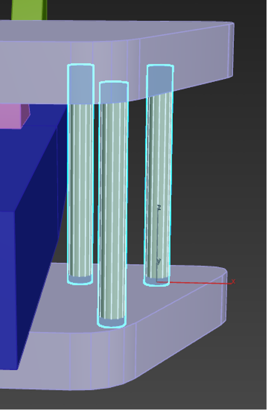
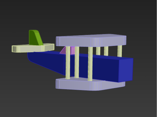
..............................................................................................................................
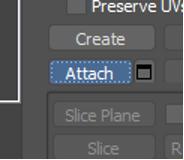
For the rods on either side of the planes wings, we duplicated a cylinder three times, spacing them out into a triangle shape. Then, with one cylinder still selected, we navigated to the right side of the screen and clicked the 'attach' button. We could then go around and click the other two pillars. This would combine the meshes together. You'll be able to tell if this endeavor was successful by clicking one of the pillars and having all three light up. A successful combining:

Then all that had to be done was mirror the object, which had to be done in a way that felt rather non-intuitive, but worked none the less.
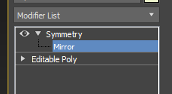
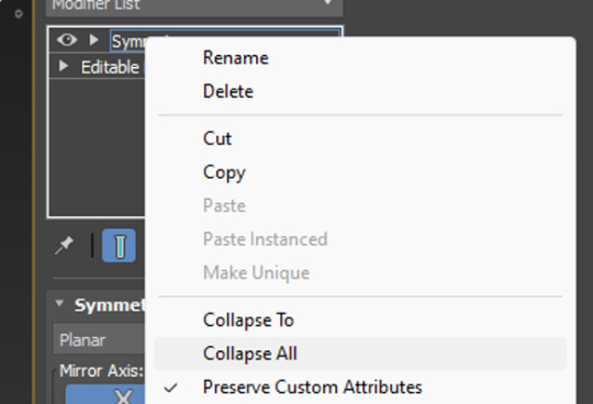
By accessing the 'modifier list' above the objects parameters, we could click the inbedded list and scroll through till we found symmetry. Once symmetry was added above our object mesh, we could click it's drop down and select mirror. Then using W,E,R, it's as easy as pulling on the mesh which will essentially duplicate it, but mirrored. To clean up, we can also collapse (basically a fancy way of saying merge) the symmetry drop down into our mesh to solidify it into one object. The many, many drop-downs needed to get there:
..............................................................................................................................
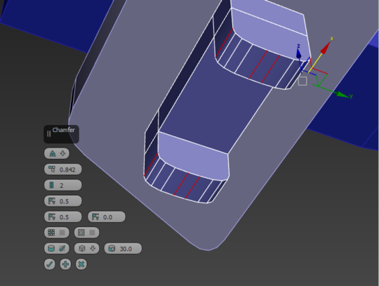
For the wheels and axle, we stuck a box on the underside of the bottom wing and added two cuts into it using the connect button (just like we did for the plane body). This time, instead of sliding the cut, however, we pinched it instead, allowing us to manipulate it and move it equally across the box. Cuts made in equal measure:

From there, we extruded the two faces either side of the cut, which adds protrusions to the original box shape, something I was familiar with thanks to last year. The height could be adjusted, and then I chamfered the edges for that nice rounded appearance.
Side note: Extruding is ten times easier in 3DS Max apparently. It tended to just... break a Maya model. Extruding protrusions:

Adding the wheels was simple. All we had to do was add a large cylinder, and inset three inner circles into it– another option that becomes available through the click of a button once the item becomes a polygon. All of this was create the illusion of hubcaps and depth on our wheels. Adding insets to the wheels to create a hubcap:
With three insets, I could double-click and use W,E,R to drag back the middle on to create a nice hubcappy illusion. I was pleasantly surprised at how nicely this worked.
The single wheel could then be duplicated and flipped using W,E,R. I chose to snap mine to my plane for accuracy, though it could have just as equally been eyeballed. A hubcap!:
And, for a little extra flare, we smoothed out the faces we created, to get rid of the janky hard-edged looked. This was as simple as selecting the ring of faces we wanted, and going to the bottom right to apply an auto-smooth. The smoothing process:

..............................................................................................................................
The final little pieces were the front cone and propellers! The propellers were easy, just another box that got the chamfer treatment, but the cones were actually a little different.
Instead of using an actual cone primitive shape, we used a simple cylinder. By cutting a connecting loop into it and sliding it down to the base, we could then select the front and scale it using W,E,R. This was the top wouldn't be entirely pointed! Though be sure to use the triangle between the side and up arrows, this ensures you'll pull the mesh in and down in a pinching motion.
Cone-ception! It's actually a cylinder:

..............................................................................................................................
0 notes
Text
My Dream Job Role
It should come as no surprise that, with all of the things I do to do with graphics, that I would like to make my graphics programming adventures to a more professional level. I spend most of my time working with things like HLSL and GLSL, whether its writing post-processing effects like screen-space reflections or simple VHS effects, or realistic PBR surface rendering and water simulations. I've spend a long time working with this sort of thing, so its only natural that I'd want to take it further.
Of course, I didn't learn graphics programming all by myself, and I am still learning things to this day. just recently I learned about creating textures on the GPU, which I used to make voxel-based global illumination in Minecraft.
First off is one of the people who actually got me into graphics programming in the first place: Sebastian Lague.
Sebastian Lague - YouTube
He has this little youtube series called "Coding Adventures" where he spends a while working on something he finds interesting. For example, recently he's been doing a lot about his 3D fluid simulator, doing things like accurate physics and rendering, as well as getting it to work on a 3D planet with tides and such. I got into graphics programming after his video on volumetric clouds, in which he did a small section on how Unity's image effect shaders work, which led me to experiment more with myself, eventually wanting to create my own volumetric clouds, which I now have.

Atmospheric scattering and procedural 3D planet generation by Sebastian Lague
Next we have Acerola.
Acerola - YouTube
Acerola does a lot of post processing things, much like Sebastian Lague, he'll do a video on something either his followers suggest or something he wants to do. His videos are all quite informative, while remaining funny, which is quite hard to do when you're talking about the physics behind ocean wave simulations and the Fast Fourier Transform.
A screenshot from Acerola's video on trying to recreate Counter Strike 2's smoke grenade
And finally, Inigo Quilez.
Inigo Quilez :: computer graphics, mathematics, shaders, fractals, demoscene and more
While he has not really helped directly, through a website he helped develop: Shadertoy, I've really found out a lot about rendering and rendering efficiently. Whereas things like raymarching and raytracing used to seem unreachable and just something I'd have to imagine creating, I now know how they work and can confidently use techniques, knowing (for the most part) how they work. Also, his website has a lot of usefull things about rendering, like signed distance functions for all of the primitive shapes (sphere, cube, etc...).

Inigo Quilez's terrain environment made entirely with raymarching and maths in Shadertoy. No pre-made textures, just maths.
0 notes
Text
3ds Max Plugins to Boost Your Productivity
Why Enroll in a 3ds Max Course in Hyderabad?
3ds Max is a powerful 3D modeling, rendering, and animation software widely used in architecture, gaming, and product design. If you’re looking to master this tool, enrolling in a 3ds Max course in Hyderabad can give you hands-on experience and expert guidance. Hyderabad, a growing hub for architects, civil engineers, and game designers, offers numerous opportunities for learning and career advancement in 3D design.

Understanding the Basics of 3ds Max
Before diving into complex modeling and animation, it’s important to understand the basic interface and tools of Autodesk 3ds Max:
1. User Interface and Navigation
Command Panel: A vital section that includes tools for modifying objects, adjusting materials, and adding animations.
Viewports: Workspaces where you create and manipulate 3D models from different perspectives.
Timeline and Animation Controls: Helps in creating smooth animations.
2. Essential Modeling Tools
Standard Primitives: Basic shapes like cubes, spheres, and cylinders to start modeling.
Editable Poly & Mesh: Advanced modeling features that allow users to refine and sculpt objects.
Spline Modeling: Helps in creating precise curves and outlines for complex designs.
3. Materials and Texturing
Material Editor: Used to apply textures and materials to objects.
UV Mapping: A technique for mapping 2D textures onto 3D objects for realistic detailing.
Shaders and Lighting: Enhances the visual appeal by controlling how surfaces react to light.
4. Rendering and Lighting
V-Ray and Arnold Render: Industry-standard rendering engines that provide photorealistic images.
Global Illumination & HDRI Lighting: Essential for realistic lighting effects.
Physical Camera Settings: Adjust camera angles, depth of field, and exposure for cinematic rendering.
Top 10 3ds Max Plugins to Boost Your Productivity
Learning 3ds Max in Hyderabad is even more beneficial when paired with powerful plugins that enhance workflow and efficiency. Here are the top 10 plugins to consider:
Forest Pack – Ideal for creating large environments with trees, grass, and other vegetation.
RailClone – A parametric modeling tool for creating complex architectural structures.
V-Ray – A rendering engine that provides photorealistic lighting and materials.
Phoenix FD – Best for fluid simulations like fire, smoke, and water.
Multiscatter – Helps create realistic scattering of objects like trees, rocks, and buildings.
Ornatrix – Used for hair, fur, and feather simulations.
Substance Painter Plugin – Integrates with 3ds Max for advanced texturing capabilities.
TopoGun – Great for retopology and optimizing high-poly models.
Floor Generator – Quickly generates realistic floor patterns and tiling.
MadCar – A vehicle rigging and animation plugin for car simulations.
Benefits of Learning 3ds Max in Hyderabad
Taking a 3ds Max course in Hyderabad ensures you gain:
Industry-relevant Training: Hands-on projects related to architecture, animation, and gaming.
Expert Guidance: Learning from industry professionals with real-world experience.
Job-oriented Curriculum: Focus on practical applications and portfolio building.
Networking Opportunities: Connect with professionals in Hyderabad’s growing design and animation industry.
Who Should Take a 3ds Max Course?
This course is ideal for:
Architects and Interior Designers – To create detailed 3D visualizations.
Mechanical and Civil Engineers – To develop realistic models for projects.
Game Designers and Animators – To craft stunning characters and environments.
Product Designers – To build and visualize product prototypes.
Conclusion
If you want to enhance your skills in 3D modeling, texturing, lighting, and animation, enrolling in a 3ds Max course in Hyderabad is a great choice. With expert trainers, hands-on projects, and career-focused learning, this course can set you on the path to becoming a professional 3D artist or designer.
Looking for the best 3ds Max training in Hyderabad? Start your journey today and unlock endless possibilities in the world of 3D design!
#3dsMax#3DModeling#Rendering#Vray#CoronaRenderer#ForestPack#RailClone#CGI#Animation#3DRendering#ArchViz#GameDev#CGArtist#Productivity#3DDesign#SiNiSoftware#PhoenixFD#AutoCAD#Architecture
1 note
·
View note