#raspberry pi pico examples
Text
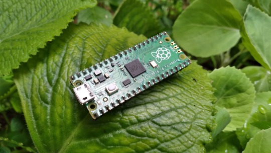
Raspberry Pi Pico: Vale a pena aprender?
Aprenda como usar todos os periféricos do Raspberry Pi Pico, Como instalar bibliotecas no Thonny IDE e ainda veja um comparativo do Pico/Pico W com ESP32, tudo em um único post.
Mais completo que isso somente o datasheet.
O Raspberry Pi Pico desde o lançamento vem sendo muito desejado por muitos projetistas, mas será que realmente vale a pena aprender? Neste post você vai aprender tudo sobre ele.
1 Surgimento do Raspberry Pi Pico
Quem acompanha a empresa Raspberry Pi, sabe que todos seus lançamentos tem um preço base para um determinado produto e o propósito disso é democratizar ao máximo o acesso aos produtos…
Ver no WordPress
#arduino nano vs raspberry pi pico#arduino raspberry pi pico i2c#arduino vs raspberry pi pico#como programar raspberry pi pico#pico raspberry pi#raspberry pi pico#raspberry pi pico adc#raspberry pi pico analog to digital#raspberry pi pico battery#raspberry pi pico datasheet#raspberry pi pico documentation#raspberry pi pico especificações#raspberry pi pico examples#raspberry pi pico pinout#thonny raspberry pi pico
0 notes
Text
Raspberry Pi Pico W has been designed to be a low cost yet flexible development platform for RP2040, with a 2.4GHz wireless interface and the following key features:
RP2040 microcontroller with 2MB of flash memory
On-board single-band 2.4GHz wireless interfaces (802.11n)
Micro USB B port for power and data (and for reprogramming the flash)
40 pin 21mmx51mm ‘DIP’ style 1mm thick PCB with 0.1″ through-hole pins also with edge castellations
Exposes 26 multi-function 3.3V general purpose I/O (GPIO)
23 GPIO are digital-only, with three also being ADC capable
Can be surface mounted as a module
3-pin ARM serial wire debug (SWD) port
Simple yet highly flexible power supply architecture
Various options for easily powering the unit from micro USB, external supplies or batteries
High quality, low cost, high availability
Comprehensive SDK, software examples, and documentation
Dual-core Cortex M0+ at up to 133MHz
On-chip PLL allows variable core frequency
264kByte multi-bank high-performance SRAM
2 notes
·
View notes
Text
Metro RP2040 Tester is ready to rock! 🔌💻🧠
We sometimes have 'Coming soon' products in the shop - this is usually when products are done and hand-verified, but the automated tester still needs to be finished. For example, this Metro RP2040 https://www.adafruit.com/product/5786, which we have the tester here. Typically metros are tested on a Raspberry Pi, but in this case, we're using the Pico Brains board https://github.com/adafruit/RP2040-Based-Tester-Brains-PCB to do it, and it's able to do all programming and test in 10 seconds - which means we can offer the Metro RP2040 at a very nice price! We'll hand this over to our test-and-prep team and schedule the work order next; you can sign up to be notified when we get the Metro RP2040 in stock next week https://www.adafruit.com/product/5786
#adafruit#raspberrypi#arduino#rp2040#opensource#opensourcehardware#electronics#metro#tester#picobrains#programming#automation#productlaunch#handverification#workorder#stocknotification#manufacturing#nyc#technology
2 notes
·
View notes
Text
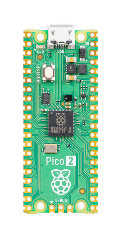
Pi Pico 2
A quick post about the #RaspberryPiPico2 (I was offline for most of the day when it was launched!) #Blaugust2024 #100DaysToOffload
I was busy and offline for most of today, and by the time I checked “the feeds” I’d missed the excitement about the Raspberry Pi Pico 2 / RP2350.
I’m somewhat excited – the RP2040 and the Pico have been staples of my electronics tinkering over the past few years – I used one in a plotter project, for example; I used one to add remote-controlled lighting to my Bambu X1C 3D printer; I’ve hacked…
View On WordPress
#Blaugust2024#100DaysToOffload#hacking#hardware#microcontroller#micropython#Raspberry Pi#raspberry pi pico 2#Technology
0 notes
Video
youtube
Fingerprint and IOT Based Exam Hall Authentication Using ESP32 | Fingerprint and iot based exam hall authentication using esp32 project | Fingerprint based exam hall authentication project report PDF | Fingerprint and iot based exam hall authentication using esp32 example | IoT based Biometric attendance system | ESP32 Fingerprint attendance system | Biometric Attendance using ESP8266 | Biometric Fingerprint Attendance System project | Biometric attendance system over IOT ppt | Iot based exam hall authentication system project with source code.***********************************************************If You Want To Purchase the Full Working Project KITMail Us: [email protected] Name Along With You-Tube Video LinkWe are Located at Telangana, Hyderabad, Boduppal. Project Changes also Made according to Student Requirementshttp://svsembedded.com/ https://www.svskits.in/ http://svsembedded.in/ http://www.svskit.com/M1: 91 9491535690 M2: 91 7842358459 We Will Send Working Model Project KIT through DTDC / DHL / Blue Dart / First Flight Courier ServiceWe Will Provide Project Soft Data through Google Drive1. Project Abstract / Synopsis 2. Project Related Datasheets of Each Component3. Project Sample Report / Documentation4. Project Kit Circuit / Schematic Diagram 5. Project Kit Working Software Code6. Project Related Software Compilers7. Project Related Sample PPT’s8. Project Kit Photos9. Project Kit Working Video linksLatest Projects with Year Wise YouTube video Links157 Projects https://svsembedded.com/ieee_2022.php135 Projects https://svsembedded.com/ieee_2021.php 151 Projects https://svsembedded.com/ieee_2020.php103 Projects https://svsembedded.com/ieee_2019.php61 Projects https://svsembedded.com/ieee_2018.php171 Projects https://svsembedded.com/ieee_2017.php170 Projects https://svsembedded.com/ieee_2016.php67 Projects https://svsembedded.com/ieee_2015.php55 Projects https://svsembedded.com/ieee_2014.php43 Projects https://svsembedded.com/ieee_2013.php1100 Projects https://www.svskit.com/2022/02/900-pr...***********************************************************1. Fingerprint Based Biometric Attendance System using Arduino,2. Fingerprint Attendance System Using Arduino || How To Make Biometric Attendance System,3. Fingerprint Based ATM System,4. Fingerprint Based Exam Hall Authentication System,5. Fingerprint Based Bank Locker System,6. How To Make Fingerprint Based Biometric Attendance System using Arduino,7. Examination room guide using RFID and FINGER PRINT for the jumbling system based EXAMS,8. Fingerprint Based Security System,9. BioMetric Exam Entry Authentication With SMS Alert GSM Based Project,10. Fingerprint Based Exam Hall Authentication,11. Electronics Projects Using Fingerprint Sensor Compilation 2023,12. BIOMETRIC FINGER PRINT BASED BANK LOCKER SECURITY USING ARM7 AND GSM TECHNOLOGY,13. Fingerprint based Exam Hall Authentication,14. Fingerprint Based Car Ignition System using Raspberry Pi Pico and RFID,15. Fingerprint Based Identity Authentication for Examination System,16. Arduino Optical Fingerprint Sensor AS608 Based Biometric Voting System,17. Biometric Security Based Examination Hall | BE / BTech / Diploma Project,18. exam hall authentication using finger scanner,19. fingerprint and iot based exam hall authentication system,20. FINGERPRINT BASED EXAM HALL EXAMINATION AUTHENTICATION || ARDTHON SOLUTIONS,21. Finger print authentication system for exam hall using R307 and PIC Microcontroller,22. Fingerprint based license verification system,23. finger print based exam hall ticket,24. Fingerprint Based Exam Hall Authentication Using IOT
0 notes
Text
E-PAPER LIBRARY <FULLSTOP>
BITMAPS -> (WIP) | SIDE NOTE
Our specimen is a 2.13" 104x212 pixel 3 color Waveshare E-paper. (I got an older model so the resolution is lower) The use of this will be saved for later, but for now let's see how pretty pictures get plopped onto that screen using a Raspberry Pi Pico. My code here. Waveshare's code here.
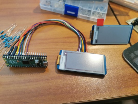
To talk to the screen, it takes 4-wire SPI. That's:
1 wire for a clock to make sure things get done at a specified pace
1 for a chip select to select which device you want to talk to
2 wires for each direction of communication. A Master Out, Slave In (MOSI (or "tx")), and a Master In, Slave Out (MISO (or "rx")). (((tx and rx depends on the perspective. When the host is Transmitting (tx), the client is Receiving (rx). When the host is Recieving (rx), the client is Transmitting (tx))))
There's also a slew of other control wires popping out including "Busy", "Reset", and "Data/Command select". These aren't part of the standard SPI system, but they're handy for controlling the screen.
Waveshare offers some of the greatest resources for new timers and hobbiests IMO. You can download a code library for their products and if it doesn't suit your needs, they're simple enough to mod yourself. And slashing the code open and wearing its skin is exactly what is going to get done.
How we decide what parts of the library to take is easy. Look at an example code that's similar to what we want, and start copying all the functions that get that job done. Then we copy all the functions it takes to run those functions. So on, until no more undefined errors show up. If any of the standard library code is undefined, #include it. If that library isn't for your board, lookup the equivalent standard library (if it exists) and translate it.
It's like plagiarism, but educational!
Let's start with a low level library to make calls to and from the board. These are like "the purest" calls possible to the screen, they can't be split up anymore.
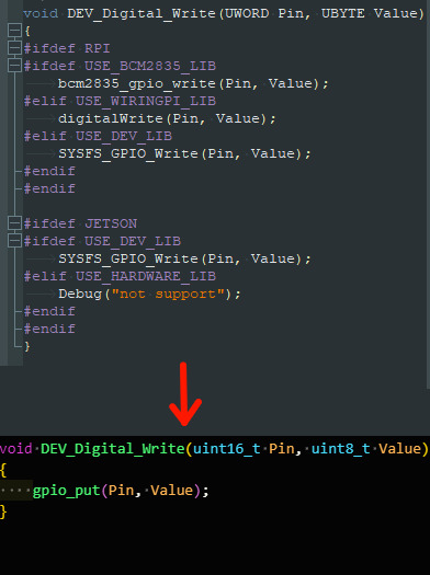
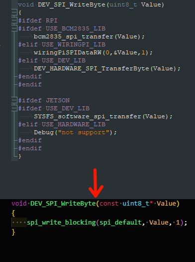

The lowest level includes
Pin read/write
SPI write
Board delay
Next is the higher level library that we are going to actually use in our code. This layer exists so we it doesn't take 15 lines of code to do a single thing and it's going to use the lower level. We're just going to bundle up a bunch of common functions into a pleasant function bun.
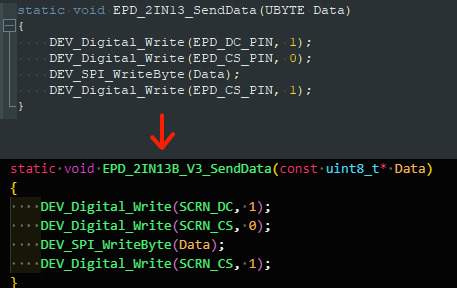
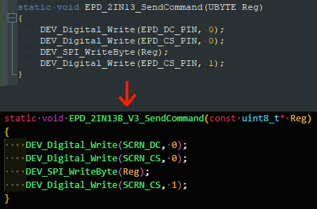
The higher level includes
Send data/command
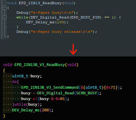
Read if the screen is busy
Turn on display
Initialize some standard settings on the display
Put the screen to sleep
Push an array of data (image) to the screen
Pushing images to the screen is actually easy (once you have the array of data ready). Just iterate through the entire array, pushing 8 bits at a time. The direction that you iterate will depend on how you want to orientate your image. You can mirror it on the horizontal and/or vertical and rotate it.
As you probably notice, most of the code is copy-pasta-ed from the original library. The point is to get it working, then it will get improved. (There's actually a mistake(?) in the "readbusy" where the delay is outside the while loop. This was in the original code too, which explains why I missed it. I just copy pasted. (Why is the code for "readbusy" so different? Well I grabbed that picture from a different version of the code. ANYWAYS))
Wonderful, we now have some copy pasted code that can control the screen. We haven't told it to do anything yet, but that will come. For now we have the screen theoretically working.
After a few rounds of testing and getting nothing on the screen, it hit me. The image file it's trying to look for doesn't exist on the board. The code right now is saying "as the code is running, look for the file called <Bleh>", but since there's no file system on the pico, it can't look for a file. Is there a way to compile files directly into the code? Probably. But I don't know how. Plan B, manually create arrays of the data for each image and #include them in a header
BITMAPS -> (WIP) | SIDE NOTE
0 notes
Text
Basic Understanding of ARM Microcontroller
ARM Microcontroller
Are you interested in learning more about ARM microcontrollers? If so, you are in the right place! In this blog post, I will explain what ARM microcontrollers are, why they are so popular, and how you can get started with them.
ARM microcontrollers are a type of microcontroller that use the ARM architecture. ARM stands for Advanced RISC Machine, which means that they use a simple and efficient instruction set that can execute faster and with less power consumption than other architectures. ARM microcontrollers are widely used in embedded systems, such as smartphones, tablets, IoT devices, and robotics.
One of the main advantages of ARM microcontrollers is that they are very versatile and scalable. You can find ARM microcontrollers with different features and performance levels to suit your needs and budget. For example, you can choose from Cortex-M series for low-cost and low-power applications, Cortex-R series for real-time and safety-critical applications, or Cortex-A series for high-performance and complex applications.
Another benefit of ARM microcontrollers is that they have a large and active community of developers and enthusiasts. You can find many resources online to help you learn and develop with ARM microcontrollers, such as tutorials, books, blogs, forums, and courses. You can also use various tools and platforms to program and debug your ARM microcontrollers, such as Arduino IDE, Keil MDK, STM32CubeIDE, mbed OS, and Raspberry Pi Pico.
If you want to get started with ARM microcontrollers, you will need some basic hardware and software components. First, you will need an ARM microcontroller board that suits your project requirements. You can find many options online from different vendors and manufacturers. Some popular examples are Arduino Nano 33 BLE Sense, STM32 Nucleo-64, Teensy 4.0, and Raspberry Pi Pico. Second, you will need a USB cable to connect your board to your computer. Third, you will need an IDE (Integrated Development Environment) to write and upload your code to your board. You can choose from the ones mentioned above or any other compatible IDE.
If you are interested to understand more about the ARM microcontrollers, then you can go through the PiEmbSysTech ARM microcontrollers Tutorial Blog. If you have any questions or query, that you need to get answer or you have any idea to share it with the community, you can use Piest Forum.
To summarize, ARM microcontrollers are a great choice for anyone who wants to learn more about embedded systems and electronics. They offer a range of features and performance levels that can fit any project idea. They also have a large and supportive community that can help you along the way. I hope this blog post has given you a basic understanding of ARM microcontrollers and inspired you to try them out. Happy coding!
0 notes
Text
Bluetooth für den Raspberry Pi Pico W
Der bliebte Microcontroller der Raspberry Pi Foundation erlaubt auch die Nutzung von Bluetooth. Jetzt gibt es mehr darüber...
Kaum ein Microcontroller steht wohl so in der Gunst der Nutzer, wie der Raspberry Pi Pico und dessen Wirelss Version Pico W. Der Pico W hat uns durch WLAN viele neue Anwendungsmöglichkeiten eröffnen. Doch was die Meißten so nicht auf dem Schirm hatten war, dass der Microcontroller von Beginn an auch über Bluetooth (BT) verfügte.
Kein Wunder, denn es gab dazu weder die nötige Software im Betriebssystem (OS/_SDK) noch Programmcode für Anwendungen, wie bspw. in Micropython. Damit liegt Bluetooth brach. Es war jedoch klar, dass sich dies ändern sollte und mit dem Update der SDK auf die Version 1.5.0, sollte sich hier etwas tun. Jetzt ist die neue Version erschienen und die ersten Beta für Bluetooths sind da.
Wir stehen jedoch im Bezug auf BT beim Pico W noch ganz am Anfang. Einige Tüfftler haben aber bereits erste Erfahrungen mit BT beim Pico W und es gibt in sofern auch bereits Code dafür. Wie das werdet ihr fragen? Die Lösung, welche das Warten auf die Onboard-BT-Funktion überbrückte war die Verwendung eines zusätzlichen BT-Modules HC-06, welches mit dem Pico W über dessen PinOuts verbunden werden konnte.
Dazu musste man vom Bluetooth Modul HC-06 den Kontakt RXD mit GP0/UART0 TX beim Pico herstellen, ferner TXD auf GP1/UART0 RX, GND auf 35(GND) und VCC auf 40/VBUS verbinden. Wenn wir von BT Verbindungen sprechen müssen wir uns auch mit dem Thema App auseinandersetze. Hier muss man nicht unbedingt eine eigene App programmieren, sondern kann ggf. sich bereits mit der Serial Bluetooth Terminal App aus dem Google PlayStore helfen.
Sicher wird es nun Anpassungen geben, die auf dem Code des HC-06 Moduls fußen und natürlich neuen Code, der im Laufe der nächsten Wochen entwickelt werden wird. Jetzt wo wir aber das Boardeigene BT des Raspberry Pi Pico nutzen können benötigen wir passende Anwendungen auf der Basis von Micropython und genau an diesem Punkt haben wir derzeit noch einen Showstopper.
Nachfolgende Links führen Dich auf Websites mit Details über BT beim PicoW und zur neuen SDK:
Doch was bringt es uns? Am Beispiel eine LED ein- und auszuschalten können wir dies beim Pico W aktuell ja sehr fein indem wir einen Webserver auf dem Pico ausführen. Jetzt könnten wir das auch über Bluetooth tun. Mhhh. Schön soweit. Steuern wir einen selbstgebauten Roboter, den wir mit einem PicoW antreiben könnte das natürlich viel nützlicher sein eine BT Verbindung dafür zu nutzen. Wir dürfen also hier ein paar neue Produkte erwarten, bei denen nun der Raspberry Pi Pico W ein wesentliches Bauteil sein wird, um beispielsweise Servos zu steuern.
0 notes
Text
Raspberry Pi Pico Programming with Rust

I’m doing a #365DaysofRust. My commitment is 15 minutes average daily of either reading about rust, or writing rust, or both.
You can see really detailed posts if you like on my blog, but I will be putting some neat little tid-bits on here with stuff I find particularly interesting.
In this post about How to Program a Raspberry Pi Pico with Rust, I cover how to configure an output pin to handle supplying 5 volts DC to some device via a specific pin (GP18) on the board.
For example:
let mut gp18 = pins.gpio18.into_push_pull_output();
This little bit of code is telling the RP2040 controller that it needs to treat GPIO18 as a Push-Pull output. Then you can reference the variable it creates “gp18″ later on, and set it’s state based on whatever conditions.
This is pretty sick! This is a crate that gives you the power to tell a piece of hardware how to behave. And if you check out the code in the HAL, you can see that there are only a few layers of abstraction in between the variable “gp18″ and setting register values manually in the controller to behave like expected.

It’s super interesting to me what’s being handled in the HAL (hardware abstraction layer), and I think maybe towards the end of the year I might try to get nitty-gritty with the bare metal if I actually stick with it.
Anyway, stick around if you want to nerd out on Rust programming and Raspberry Pi Pico stuff!
1 note
·
View note
Text
A Modern Tribute To The Classic HP-16C Calculator
A Modern Tribute To The Classic HP-16C Calculator
The HP-16C Computer Scientist is much beloved as the only dedicated programmer’s calculator that Hewlett-Packard ever made. Most surviving examples in the world are well-used, and you haven’t been able to order one from HP since 1989. Thus, [K Johansen] set about building a tribute to the HP-16C using modern hardware.
The build relies on a Raspberry Pi Pico as the brains of the operation. As with…
View On WordPress
0 notes
Text
Arduino camera opencv

Arduino camera opencv how to#
Arduino camera opencv android#
VideoCapture cap = new VideoCapture(RTSP_URL, Videoio. Setenv("OPENCV_FFMPEG_CAPTURE_OPTIONS", "rtsp_transport udp", 1) _putenv_s("OPENCV_FFMPEG_CAPTURE_OPTIONS", "rtsp_transport udp") import cv2Ĭap = cv2.VideoCapture(RTSP_URL, cv2.CAP_FFMPEG) Reolink E1 Pro camera has been used for testing. High Security Surveillance Camera using OpenCV Python & Arduino. In your case, I would use Raspberry Pi + camera to capture images/videos. Im trying to use OpenCV via Python to find multiple objects in a train image and match. So, I had a question 'can I have a face id for my Arduino project' and the answer is yes. For example, Azure, Bluemix or your main computer. Face Recognition and Identification Arduino Face ID Using OpenCV Python and Arduino.: Facial recognition AKA face ID is one of the most important feature on mobile phones nowadays. but, you can use Arduino/Raspberry Pi to capture information and send it to a server for analysis. Both devices (webcam and Arduino are connected to the same computer via. The pushbutton is on a breadboard and is connected to pin 10 on said Arduino device. The Arduino Uno is connected to the same Windows PC that the webcam is connected to. A window can be closed by pressing ESC key (represented as ASCII code 27). As some people said before, you just can't run OpenCV on Arduino. OpenCV is running in the Anaconda Spyder IDE within the same Windows PC that is connected to the webcam. RTSP URL usually consists of username, password, IP address of the camera, port number (554 is default RTSP port number), stream name.Ĭaptured frames displayed in the window using imshow function. Simply place the phone in our mobile holder and sit in. The Application will automatically connect to the HC-05 (must be named HC-05) Bluetooth module and will wait for a face to be detected.
Arduino camera opencv android#
Simply power your Arduino and open the android application. Many manufacturers provide RTSP URL on their website or user manual. Once we are ready with our hardware, code and Android Application its time for some action. Since RTSP URL is not standardized, different IP camera manufacturers might use different RTSP URLs. To capture RTSP stream from IP camera we need to specify RTSP URL as argument. OpenCV provides VideoCapture class which allows to capture video from video files, image sequences, webcams, IP cameras, etc.
Arduino camera opencv how to#
This tutorial provides example how to capture RTSP stream from IP camera using OpenCV and Python. Most of the IP cameras supports Real Time Streaming Protocol (RTSP) to control audio and video streaming. Arduino Cameras STM32 Camera Modules ESP32/ESP8266 Camera Raspberry Pi Pico Camera BBC micro:bit Cameras USB 3 Camera Dev Kit USB Webcam (UVC Camera) Camera Breakout Board OEM/Compact Camera Modules Lenses Optical Filters Applications Discuss.
0 notes
Text
Raspberry Pi Pico W - Creator Display erstellen

In diesem Beitrag möchte ich dir zeigen, wie du deinen Raspberry Pi Pico W mit einem OLED Display in ein Creator Display verwandeln kannst und dort deine Social-Media Attribute anzeigen lässt.
Natürlich kannst du dieses Beispiel auch recht einfach adaptieren und dort andere Daten von APIs anderer Dienste anzeigen, wie zbsp. vom Deutschen Wetterdienst, Umrechnungskurse, Aktienkurse etc.
Da wir das spätere Programm in MicroPython schreiben, können wir auch einen anderen Mikrocontroller als den Raspberry Pi Pico W verwenden. Jedoch ist dieser derzeit meine erste Wahl und wird für dieses kleine Projekt eingesetzt.
Was soll das Creator Display anzeigen?
Ziel soll es sein, auf einem Display die Aufrufe und Abos anzeigen zu lassen.
https://youtu.be/YE9z9fq-dnc
Da mein YoutTube Kanal Draeger-IT noch recht klein ist, habe ich noch nicht so viele Abos und auch nicht die Masse an Aufrufe, aber trotzdem möchte ich die YouTube API ansprechen, um die Daten zu empfangen und auszuwerten.
Hier eine kleine Auflistung der APIs zu welchen man recht einfach Zugriff bekommt:
- YouTube,
- Instagram,
- Pinterest,
- Facebook,
- TikTok
In diesem Beitrag möchte ich mich zunächst auf die YouTube API beschränken. Die anderen Social-Media-Plattformen werden ggf. in separaten Beiträgen behandelt.
Benötigte Ressourcen für dieses Projekt
Damit du Zugriff auf die YouTube API bekommst, benötigst du einen Google Account und einen API Key. Den API Key kannst du dir nur mit einem Google Developer Account anlegen und unter https://console.cloud.google.com/apis/ anlegen.
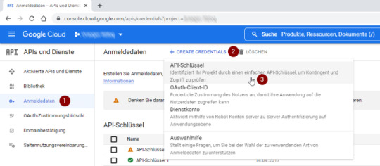
Um einen API Key zu generieren, klicken wir zunächst im Navigationsmenü auf der linken Seite auf "Anmeldedaten" (1) und können dann auf "+ CREATE CREDENTIALS" (2) klicken.
Im neu geöffneten Untermenü kannst du den ersten Eintrag "API-Schlüssel" (3) wählen und ein allgemeingültiger API-Schlüssel wird erzeugt.
Schritt 1 - erstellen eines API Keys im Google Developer Account
Nach einer kurzen Wartezeit wird dir der API Key in einem Dialog angezeigt, welchen du dir in die Zwischenablage kopieren kannst.
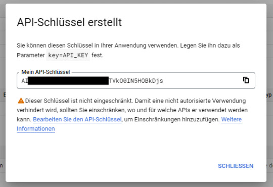
Schritt 2 - neu generierter API Key
Achtung: Mit dem API Key kannst du auf einfache Weise auf deinen Account zugreifen und Daten hinzufügen und auch ändern. Den hier dargestellten API Key habe ich gegen Missbrauch unkenntlich gemacht und auch nach der Erstellung von diesem Beitrag wieder gelöscht.
Aufruf der YouTube API per HTTP Request
Am Einfachsten kannst du über einen simplen HTTP Request auf die YouTube API zugreifen, du benötigst also keine zusätzlichen Module, welche du importieren musst.
Du kannst mit deinem zuvor generierten API Key somit recht einfach eine URL zusammensetzen und wie hier die aktuelle Kanalstatistik als JSON abrufen.
https://www.googleapis.com/youtube/v3/channels?id=UCUoqALbWy__4Blgfztg4sKg&key=AIzaSyD*********F3AJHs&part=statistics
{
"kind": "youtube#channelListResponse",
"etag": "MozCK4S3NxXniTguDkimSgach7g",
"pageInfo": {
"totalResults": 1,
"resultsPerPage": 5
},
"items":
}
Im letzten Beitrag Raspberry Pi Pico W – Zeit aus dem Internet lesen und auf einem Display anzeigen habe ich dir bereits gezeigt, wie du eine Zeit von einem Server als JSON Response anfordern und auswerten kannst. Jedoch müssen wir auf die API per SSL zugreifen und daher müssen wir etwas umschreiben.
Aufbau einer SSL Verbindung mit dem Modul ussl
Das nachfolgende Beispiel habe ich von der Seite Python ussl.wrap_socket() Examples entnommen und dieses hat auf Anhieb quasi ohne Änderungen funktioniert.
Der Vorteil ist an der erweiterten Funktion, dass diese mit HTTP & HTTPS arbeiten kann. Damit wir die SSL Verbindung aufbauen können, müssen wir zunächst das Modul ussl in die Thonny IDE einbinden.
Über das Hauptmenü "Extras" > "Verwalte Pakete..." erreichst du den Dialog zum Installieren neuer Module.
In diesem Dialog suchst du zunächst nach "ussl" (1), mit der Schaltfläche "Suche auf PyPi" (2) aus den Suchergebnissen wählst du den Eintrag "pycopy-cpython-ussl" (3) aus. Nach dem Selektieren des Eintrages aus den Suchergebnissen kannst du dann die Schaltfläche "Installieren" (4) betätigen und das Modul wird hinzugefügt.
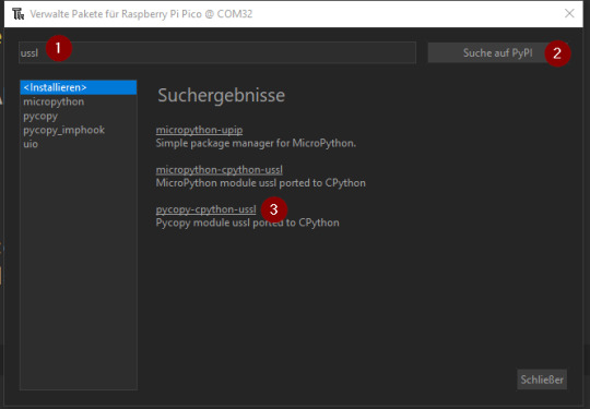
installieren des Modules "ussl" in der Thonny IDE Schritt 1

installieren des Modules "ussl" in der Thonny IDE Schritt 2
Im Ordner "lib" des Mikrocontrollers findest du nun die Datei "ussl.py".

Installierte Module auf dem Pi Pico W
Hier die angesprochene Funktion zum Absenden eines HTTP / HTTPS Request und liefern des Response.
import ussl
# Funktion zum absenden eines HTTP / HTTPS Request und
# Rückgabe des Response
# Quelle: https://www.programcreek.com/python/example/96165/ussl.wrap_socket
def http_get(url):
print("Fetching:", url)
proto, _, host, path = url.split('/', 3)
if proto == "http:":
port = 80
elif proto == "https:":
port = 443
addr = socket.getaddrinfo(host, port)
s = socket.socket()
s.connect(addr)
if proto == "https:":
s = ussl.wrap_socket(s, server_hostname=host)
s.write(bytes('GET /%s HTTP/1.0rnHost: %srnrn' % (path, host), 'utf8'))
result = ''
while True:
data = s.read(100)
if data:
result = result + str(data, 'utf8')
else:
break
s.close()
return result
Die Rückgabe ist nicht nur ein einfacher HTTP/HTTPS Response, sondern auch die gesamten Header Daten.
Waiting to connect:
('192.168.178.70', '255.255.255.0', '192.168.178.1', '192.168.178.1')
Fetching: https://www.googleapis.com/youtube/v3/channels?id=UCUoqALbWy__4Blgfztg4sKg&key=AI******3AJHs&part=statistics
HTTP/1.0 200 OK
Content-Type: application/json; charset=UTF-8
Vary: X-Origin
Vary: Referer
Date: Sun, 31 Jul 2022 09:25:38 GMT
Server: scaffolding on HTTPServer2
Cache-Control: private
X-XSS-Protection: 0
X-Frame-Options: SAMEORIGIN
X-Content-Type-Options: nosniff
Accept-Ranges: none
Vary: Origin,Accept-Encoding
Alt-Svc: h3=":443"; ma=2592000,h3-29=":443"; ma=2592000,h3-Q050=":443"; ma=2592000,h3-Q046=":443"; ma=2592000,h3-Q043=":443"; ma=2592000,quic=":443"; ma=2592000; v="46,43"
{
"kind": "youtube#channelListResponse",
"etag": "nJfSIGqHLEeyYpfTt3arnG3kax0",
"pageInfo": {
"totalResults": 1,
"resultsPerPage": 5
},
"items":
}
Funktion zum Extrahieren des JSON Response
Wie du erkennen kannst, liefert die Funktion noch zusätzliche Daten, welche wir in diesem Fall nicht benötigen. Mit einfachen nachfolgenden Funktion können wir den JSON Response extrahieren.
# Ermitteln des JSONs aus dem HTTP Response
def findJson(response):
return response
Als Parameter übergeben wir das Result der Funktion "http_get(url)" und erhalten unser JSON.
{
"kind": "youtube#channelListResponse",
"etag": "nJfSIGqHLEeyYpfTt3arnG3kax0",
"pageInfo": {
"totalResults": 1,
"resultsPerPage": 5
},
"items":
}
Auswerten des JSON Response
Wenn du die Adresse im Browser ausgeführt / abgesendet wird, erhält man wie erwähnt eine Antwort mit einem JSON aus welchem man die nachfolgenden Werte entnehmen kann:
- viewCount - Anzahl der gesamten Klicks auf Videos
- subscriberCount - Anzahl der Abos
- videoCount - Anzahl der Videos
Zunächst wandeln wir das JSON Objekt in ein Dictionary um, denn so können wir ganz einfach auf die Werte zugreifen.
import json
aDict = json.loads(jsonData)
{'pageInfo': {'resultsPerPage': 5, 'totalResults': 1}, 'kind': 'youtube#channelListResponse', 'etag': 'nJfSIGqHLEeyYpfTt3arnG3kax0', 'items': }
Dun kann man mit dem Key "statistics" auf die oben aufgeführten Werte zugreifen.
aDict = json.loads(jsonData)
statistics = aDict
subscriberCount = statistics
videoCount = statistics
viewCount = statistics
print('subscriberCount', subscriberCount, sep=" ")
print('videoCount', videoCount, sep=" ")
print('viewCount', viewCount, sep=" ")
subscriberCount 342
videoCount 301
viewCount 122093
Programmieren des Raspberry Pico W Creator Display
Nachdem wir die Daten ermittelt haben, wollen wir diese jetzt auf einem OLED Display anzeigen lassen.
Für den Arduino, ESPx sowie natürlich für den Raspberry Pi / Pico / Pico W bekommst du diverse OLED Displays in verschiedene Auflösungen und auch Farben.
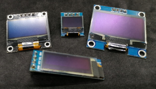
Auswahl an OLED Displays für den Arduino, ESPx und Raspberry Pi
Im nachfolgenden Beispiel verwende ich das 0,96" OLED Display mit einer Auflösung von 128 x 64 Pixel.
Anschließen eines OLED Displays per I²C an den Pi Pico / Pico W
Zunächst schließen wir unser OLED Display per I²C an den Pi Pico W an. Hier verwende ich die folgende Pinbelegung:
- GND - Pin 38, GND
- VCC - Pin 40, VBUS
- SCL - Pin 1, GP1
- SDA - Pin 0, GP0

Schaltung - OLED Display am Raspberry Pi Pico
Installieren des Modules für das OLED Display mit SSD1306 Chip
Auf dem OLED Display ist ein Chip vom Typ SSD1306 verbaut, für die Programmierung benötigen wir das Modul "micropython-ssd1306" welches wir ebenfalls wie zuvor das "ussl" Modul über "Extras" > "Verwalte Pakete..." installieren.
Wir suchen somit nach "ssd1306" (1) mit der Schaltfläche "Suche auf PyPi" (2) oder betätigen einfach die Return taste. In den Suchergebnissen wählen wir den ersten Eintrag "micropyhton-ssd1306" aus und wählen im nächsten Dialog die Schaltfläche "Installieren", wenn der vorgang
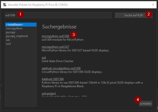
Thony IDE - installieren des Modules "micropython SSD1306"
Ausgabe der Zeile "Hello World!" auf dem OLED Display
In der offiziellen Dokumentation zum Modul "micropython-ssd130" unter Using a SSD1306 OLED display findest du weitere Informationen, wie man ein OLED Display in MicroPython programmiert.
Hier nun ein kleines Beispiel, wie man die Textzeile "Hello World!" ausgibt.
from machine import Pin, I2C
import ssd1306
import time
i2c = I2C(0, sda=Pin(0), scl=Pin(1))
time.sleep(3)
display = ssd1306.SSD1306_I2C(128, 64, i2c, addr=0x3c)
display.fill(0)
display.text('Hello World!', 0, 0, 1)
display.show()

Textzeile "Hello World!" auf dem OLED Display via I²C am Raspberry Pi Pico W angeschlossen
Das Display kann maximal 6 Zeilen mit jeweils 16 Zeichen vernünftig anzeigen.

Anzeige der maximalen Zeilenzahl am 128x64 Pixel OLED Display
Fertiges Skript "Raspberry Pi Pico W Creator Display"
Hier nun das fertige Skript zum Laden der YouTube Statistik zu einem Kanal mithilfe der API und einem generierten API_KEY.
import network
import socket
import time
import json
import ssl
import ussl
from machine import Pin, I2C
import ssd1306
i2c = I2C(0, sda=Pin(0), scl=Pin(1))
time.sleep(3)
display = ssd1306.SSD1306_I2C(128, 64, i2c, addr=0x3c)
#Zugangsdaten zum WLAN Netzwerk
ssid = '*****'
password = '******'
#Adresse welche uns das JSON mit den Zeitdaten liefert
CHANNEL_NAME = 'Draeger-IT'
CHANNEL_ID = 'UCUoqALbWy__4Blgfztg4sKg'
API_KEY = 'AIz****AJHs'
url = "https://www.googleapis.com/youtube/v3/channels?id={}&key={}&part=statistics".format(CHANNEL_ID, API_KEY)
# Aufbau einer WiFi Verbindung
def wifiConnect():
wlan = network.WLAN(network.STA_IF)
wlan.active(True)
wlan.connect(ssid, password)
print("Waiting to connect:")
while not wlan.isconnected() and wlan.status() >= 0:
print(".", end="")
time.sleep(1)
print("")
print(wlan.ifconfig())
# Funktion zum absenden eines HTTP / HTTPS Request und
# Rückgabe des Response
# Quelle: https://www.programcreek.com/python/example/96165/ussl.wrap_socket
def http_get(url):
print("Fetching:", url)
proto, _, host, path = url.split('/', 3)
if proto == "http:":
port = 80
elif proto == "https:":
port = 443
addr = socket.getaddrinfo(host, port)
s = socket.socket()
s.connect(addr)
if proto == "https:":
s = ussl.wrap_socket(s, server_hostname=host)
s.write(bytes('GET /%s HTTP/1.0rnHost: %srnrn' % (path, host), 'utf8'))
result = ''
while True:
data = s.read(100)
if data:
result = result + str(data, 'utf8')
else:
break
s.close()
return result
# Ermitteln des JSONs aus dem HTTP Response
def findJson(response):
txt = '{'
return response
def displayYouTubeStatistics(text, value):
display.fill(0)
display.text('YouTube channel', 0, 0, 1)
display.text(CHANNEL_NAME, 0, 15, 1)
display.text(text, 0, 30, 1)
display.text(str(value), 0, 45, 1)
display.show()
# Main Funktion
def main():
# Aufbau der Wifi-Verbindung
wifiConnect()
# Auslesen des HTTP Response
response = http_get(url)
#print(response)
# ermitteln des JSONs
jsonData = findJson(response)
# umwandeln des JSONs in ein Dictionary
aDict = json.loads(jsonData)
statistics = aDict
subscriberCount = statistics
videoCount = statistics
viewCount = statistics
print('subscriberCount', subscriberCount, sep=" " )
print('videoCount', videoCount, sep=" " )
print('viewCount', viewCount, sep=" " )
pause = 2.5
displayYouTubeStatistics('subscriberCount', subscriberCount)
time.sleep(pause)
displayYouTubeStatistics('videoCount', videoCount)
time.sleep(pause)
displayYouTubeStatistics('viewCount', viewCount)
time.sleep(pause)
# Aufrufen der Funktion main()
while True:
main()
# eine Pause von 5 Minuten einlegen
# Der Server leht die Verbindung ab wenn der Intervall
# des Zugriffs zu klein ist.
time.sleep(300)
Read the full article
0 notes
Text
RP2040 USB host to program ESP chips through CDC chips
Historically, we've tested and programmed our Feather ESP8266 (https://www.adafruit.com/product/2821) and ESP32 boards (https://www.adafruit.com/product/3405) from a Raspberry Pi. We'd connect over USB and run esptool.py, which works fine but has more things that can go wrong: power flickering, SD card failures, etc. It's better to fully program it with a Pico RP2040 brain board. We can do that now because TinyUSB has support for USB CDC Serial chips (https://github.com/adafruit/Adafruit_TinyUSB_Arduino/tree/master/examples/DualRole/CDC/serial_host_bridge) like the FT232, CP210x, and WCH9102! We upload the stub and test firmware, then listen on the CDC for the self-test output. It works really fast and is much easier to manage.
#Adafruit#ESP8266#ESP32#RaspberryPi#esptool#USB#TinyUSB#PicoRP2040#FirmwareProgramming#CDCSerialChips
1 note
·
View note
Text
youtube
Unveiling the Raspberry Pi Pico 2: Power, Security, and Innovation in a $5 Microcontroller by Livio Andrea Acerbo
Unveiling the Raspberry Pi Pico 2: Power, Security, and Innovation in a $5 Microcontroller #RaspberryPi, #Pico2, #TechInnovation, #Microcontroller, #IoT, #ARMProcessors, #SecurityTech, #TechNews, #TechPodcast, #DIYElectronics In this episode of GreenGround, we explore the groundbreaking launch of the Raspberry Pi Pico 2, a powerful and secure microcontroller packed with advanced features—all for just $5. Learn about the new dual-core ARM Cortex-M33 processors, enhanced security with Arm TrustZone, and future wireless capabilities. Whether you’re a tech enthusiast or a seasoned developer, this is an episode you won’t want to miss. Tune in to discover how this tiny board is set to revolutionize your projects. Like, comment, and subscribe for more tech insights and innovations! Sources: 1. Ten Tips to Create the Best Podcast Content - Transkriptor https://ift.tt/ATa6jtB 2. How to Create A Great Video Podcast: Lessons from Five Podcasters https://ift.tt/KmGPO7L 3. How to Keep Your Video Podcast Audience Interested https://ift.tt/equA1PD 4. Eight Podcast Formats To Consider For Your Show - Castos https://ift.tt/BZWuOto 5. Podcast Format Possibilities: Scripted Monologue - MSR https://ift.tt/oXE7kji 6. The Top Influencer Podcasts You Need to Know About - IZEA https://ift.tt/xlXk6WP 7. Five Branded Podcast Examples - Storytelling - JAR Audio https://ift.tt/TKM56zb 8. Top Technology Influencers on Instagram Today - BENlabs https://ift.tt/fSk06Q4 9. Talking to Yourself: Creating Engaging Monologue - The Podcast Host https://ift.tt/ANW47e2 Remember, if you want to stay updated with the latest trends, news, and tech reviews, don’t forget to like and subscribe to Greenground! Follow up on our website https://ift.tt/fk6sa9H or follow up on our social #fyp, #foryou, #love, #explorepage, #trending, #reviews, #news #YouTube: https://youtube.com/#TikTok: https://ift.tt/1uGhOoe: https://ift.tt/jQZqkra #X(Twitter): https://ift.tt/dLeIPvl #Instagram: https://ift.tt/TCpuijq #Podcast: https://ift.tt/bAjKZX8 #Medium: https://ift.tt/Ka2sJyH: https://ift.tt/LeuRVJW #Reddit: https://ift.tt/a6Jf1sl #Rumble: https://ift.tt/KBhLJN3
via YouTube https://www.youtube.com/watch?v=5lz9EF7VDTE
0 notes
Text
Create an access point with the Raspberry Pi Pico W, serve a web-page and flash the LEDCreate an access point with the Raspberry Pi Pico W, serve a web-page and flash the LED
Following various examples, I’ve created a MicroPython script that does the following:
Create an access point on the Raspberry Pi Pico W.
Create a web server.
Serve a simple page on that web server.
Toggle/flash the on-board LED when that page is loaded/refreshed.
TL;DR – see the code here
Download MicroPython and install it
First of all, you’ll need to download the latest MicroPython UF2. The…

View On WordPress
1 note
·
View note
Text
Half-true call-out posts for makers of consumer electronics, smartphones and desktop computers are so boring. Instead we should do more about these for microelectronics and the like. With that in mind, here’s mine:
Stop buying Arduino, they’re problematic.
Note: I think it’s perfectly okay to buy a cheap knock-off of the Arduino Uno, Nano or Mega; I have dozens of them myself. I mean from the actual company itself. Yes, buying there funds their open source development and project, but honestly, I think they have enough money, considering what they’re spending it on, with their MKR range, the whole Arduino Pro/Potenta stuff and so on. The Arduino Uno and Nano are really complete products. Maybe they (or someone) will make a version with a USB-C plug, but that’s about all the development this needs. Ιf you want more power, the Raspberry Pi Pico or the whole STM32 range are right there, and the Raspberry Pi Pico is incredibly cheap.
Plus, it’s not like the Arduino guys are that great people to begin with. Consider the whole Arduino/Genuino split, or the way the project was an end-run around Wiring (at least according to the Wiring guy).
Yes, these guys do provide the (long finished) framework and the IDE. But on the flip side, they provide this IDE. It’s crap, it’s always been crap, and it has long passed the point where its hacked-together charm was endearing. Maybe 2.0 will be better, I know it’s supposed to be out soon. But I’ve already switched to PlatformIO long ago and I’m not looking back.
Now I’m not saying don’t support open source hardware and related projects. I’ve donated to KiCad, for example. And if you genuinely need the high-end boards that Arduino provides, well, knock yourself out.
But for the basic foundational beginner projects, where you just need to blink a LED with minimal setup time, my recommendation is to buy a clone (or many clones, they’re cheaper in bulk), or look at the more modern alternatives.
0 notes
Last Seen Blogs

junho-writing
the mighty lava lamp

gunnslaughter
Gunnslaughter Art

lonny2x4
2x4

mitigatingcircumstance
Hallucinating Like Hell And Not Doing Well

younghairdostudentcookie
Untitled