#raspberry pi pico battery
Explore tagged Tumblr posts
Visit Tumblr Blog
Explore Tumblr blogs with no restrictions, modern design and the best experience.
Last Seen Tumblr Blogs


Fun Fact
Tumblr has 4 main sources of revenue.
Text

(Me who tried hours trying to figure out how to actually make one [for home safety purposes of course]. Some components you do need is a raspberry pi(Pico would probably work?), motion sensor n a small camera which I couldn't figure out. Both needs to be small enough to be hidden n also be good enough to be camouflage and not really power hungry. Also a wireless battery too. All of this needs to be custom made with a teddy bear afterwards including the software. The problem comes when trying to get the data which you either could connect to a wifi locally or you need to be close enough to the doll to download it off bluetooth or smth if you configure that. Of course the battery is not gonna last forever too. Overall it would be easier to use the webcam through the pc or the front camera on the phone [to look at your own face])
#obsessive tendencies#obsessive yandere#extreme yandere#actually obsessive#soulmates#unconditional love#yan blog#yanblr#yandere#actually bpd#actually mentally ill#obsessive love#yandere girl#yandere thoughts#actually yandere#yandere community#yandere tendencies#obslove#yancore#irl yan#yande.re#obsessive thoughts#bpd#fetishizers stay out!!!
16 notes
·
View notes
Text
Raspberry Pi Pico W has been designed to be a low cost yet flexible development platform for RP2040, with a 2.4GHz wireless interface and the following key features:
RP2040 microcontroller with 2MB of flash memory
On-board single-band 2.4GHz wireless interfaces (802.11n)
Micro USB B port for power and data (and for reprogramming the flash)
40 pin 21mmx51mm ‘DIP’ style 1mm thick PCB with 0.1″ through-hole pins also with edge castellations
Exposes 26 multi-function 3.3V general purpose I/O (GPIO)
23 GPIO are digital-only, with three also being ADC capable
Can be surface mounted as a module
3-pin ARM serial wire debug (SWD) port
Simple yet highly flexible power supply architecture
Various options for easily powering the unit from micro USB, external supplies or batteries
High quality, low cost, high availability
Comprehensive SDK, software examples, and documentation
Dual-core Cortex M0+ at up to 133MHz
On-chip PLL allows variable core frequency
264kByte multi-bank high-performance SRAM
2 notes
·
View notes
Text
Warum der Arduino trotz ESP32 & Co. nicht ausgedient hat

„Arduino? Das nutzt doch heute keiner mehr…“ Wer sich in den letzten Jahren mit Mikrocontrollern beschäftigt hat, stolpert überall über den ESP32. Dual-Core, WLAN, Bluetooth, 240 MHz, massig Speicher – und das alles für ein paar Euro. Kein Wunder also, dass der gute alte Arduino UNO im Schatten der neuen Mikrocontroller-Generation zu stehen scheint. Die Kommentare in Foren und Social Media klingen dann auch oft so: „Warum noch einen Arduino benutzen, wenn es doch den ESP32 gibt?“ Aber ist das wirklich so? Hat der Arduino tatsächlich ausgedient? Oder gibt es gute Gründe, auch heute noch auf den betagten Klassiker zu setzen? Und vor allem: Wenn ich gerade erst einsteige – sollte ich dann überhaupt noch mit einem Arduino anfangen, oder direkt auf einen ESP32 setzen? Genau um diese Fragen geht es in diesem Beitrag. Und so viel sei schon mal verraten: Leistung ist nicht immer alles.
ESP32 – das moderne Powerpaket (aber nicht für alles nötig)
Wenn man sich heute in der Maker-Szene oder auf YouTube umschaut, könnte man fast glauben, es gäbe nur noch den ESP32. Und das ist auch gar nicht so abwegig: Der ESP32 bringt schon ab Werk eine ganze Menge beeindruckender Features mit, die früher nur mit viel zusätzlicher Hardware möglich waren. 🔥 Ein kurzer Blick auf die Highlights: - Dual-Core mit bis zu 240 MHz - WLAN und Bluetooth direkt integriert - Bis zu 520 kB RAM und mehrere Megabyte Flash - Viele GPIOs, PWM, ADC, DAC, I2C, SPI, CAN, Touch-Sensoren, … - Bereits ab ca. 3 € (je nach Ausführung und Händler)
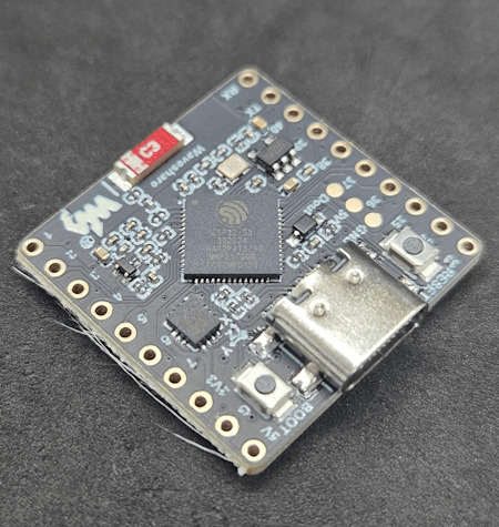
ESP32-S3-Matrix
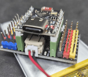
ESP32-C3 mit LiPo Batterie
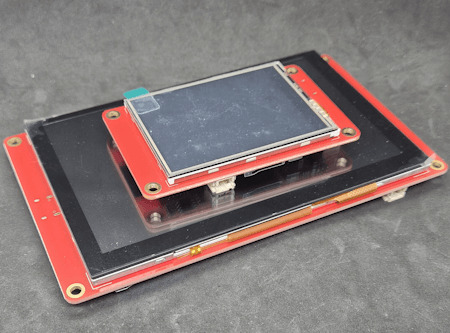
zwei Elecrow CrowPanels 2,4" & 5.0"
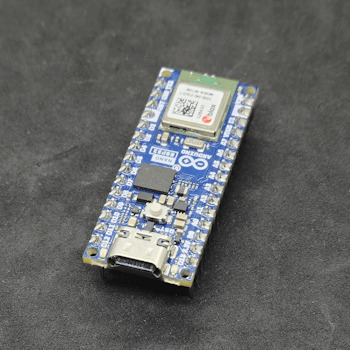
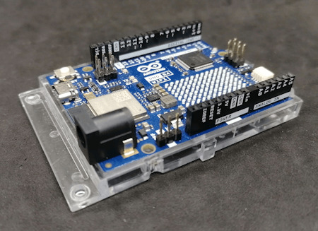
Arduino Nano ESP32
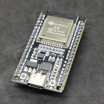
Generic-ESP32 Mikrocontroller

ESP32-C3 Super Mini

ESP32-S3-Zero Und dann wäre da noch ein echter Publikumsliebling: die ESP32-CAM.

Vergleich ESP32-CAM und ESP32-S3 CAM

ESP32-CAM mit externer Antenne und Board

ESP32-CAM

ESP32-CAM Modelle Für rund 5 € bekommt man hier nicht nur die Rechenpower des ESP32, sondern auch gleich eine kleine Kamera mit bis zu 5 Megapixeln dazu. Damit sind Projekte wie: - Überwachungskamera, - QR-Code-Scanner, - Fotos per E-Mail oder Telegram senden ganz einfach umsetzbar – ohne zusätzliche Hardware. Der Raspberry Pi Pico (RP2040) mischt kräftig mit – und bekommt Verstärkung Doch der ESP32 ist nicht allein auf dem Platz. Der Raspberry Pi Pico mit seinem RP2040 Dual-Core Cortex-M0+ Prozessor (133 MHz) hat sich schnell als leistungsfähige und günstige Alternative etabliert – und das in mehreren Varianten: BoardWLANBluetoothBesonderheitenRaspberry Pi Pico❌❌Basisversion, ohne FunkRaspberry Pi Pico W✅✅ (per Firmware)WLAN onboard, BT aktivierbarRP2350-Boards❌❌Mehr Power, keine Funkmodule (derzeit)


RP2040:bit
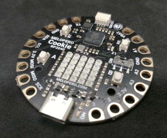
Melopero Cookie RP2040
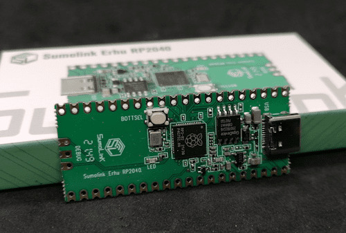
Sumolink Erhu RP240

Mikrocontroller - XIAO RP2040 & Raspberry PI Pico

Raspberry Pi Pico 2 - RP2350A

XIAO RP2350 Mit dem neuen RP2350-Chip steht mittlerweile ein leistungsstärkerer Nachfolger in den Startlöchern. Er wird derzeit auf einigen neuen Boards verbaut (z. B. auf Prototypen oder Dev-Boards asiatischer Hersteller) und bringt: - Höhere Taktraten (bis 200 MHz möglich), - Verbesserte Peripherie, - Und bleibt trotzdem kompatibel zur RP2040-Familie. Was aktuell noch fehlt: WLAN und Bluetooth sind (noch) nicht integriert – was den Chip für reine IoT-Projekte (noch) weniger attraktiv macht, aber für USB-HID oder Highspeed-Sensoranwendungen interessant sein kann.
Arduino – Der Klassiker mit Kultstatus (und vielen Gesichtern)
Wenn man „Arduino“ sagt, denken viele sofort an das gute alte Original: Arduino UNO R3, Made in Italy, stabil, bewährt – aber auch nicht ganz billig. Und genau da beginnt der kleine Konflikt, den vermutlich viele kennen: ➡️ Das originale Board unterstützt die Plattform, die Entwicklung und das Open-Source-Projekt. ➡️ Aber: Der Preis liegt oft bei 20 € und mehr – während Clones für 2–3 € zu haben sind. Doch: Genau das ist eben auch der Spirit von Open Source. Die Arduino-Plattform wurde so entwickelt, dass jeder (mit Einhaltung gewisser Auflagen) eigene Boards bauen und verkaufen darf. Und das tun viele Hersteller – vor allem in Asien. Dabei gibt es längst nicht nur einfache UNO- oder Nano-Kopien. Die Vielfalt an Arduino-kompatiblen Boards ist inzwischen riesig: Board / CloneBesonderheitPreisbereichNano Clone (CH340G)Klassiker für einfache Projekte2–4 €Pro MiniOhne USB, super klein und sparsam2–4 €Nano mit integriertem OLEDAnzeige direkt am Mikrocontroller4–8 €Nano mit 2,4 GHz Funk (nRF24L01) oder 433 MHz ModulIdeal für Funkprojekte ohne WLAN5–10 €Nano mit ESP8266-Modul onboardWLAN-fähig, bleibt aber Arduino-kompatibel5–10 €Nano mit Bluetooth HC-05 oder HM-10Kabellose Kommunikation über BT Classic oder BLE5–10 €

Arduino Nano mit nRF24L01 Erweiterungsboard

Microcontroller BLE-Nano von Keywish

Arduino UNO R3
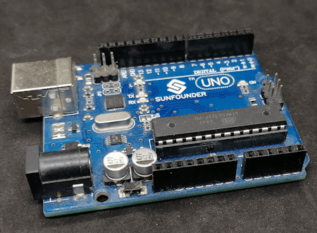
Arduino UNO R3 Clone von der Firma Sunfounder


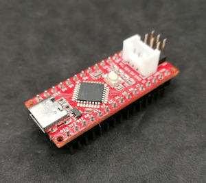
Arduino Nano V3 , ATmega328P

Arduino Mega 2560 Pro mini

Arduino Nano V3
Seeeduino Nano Gerade diese Vielfalt an spezialisierten Clones und Abwandlungen ist ein echter Vorteil: Man wählt sich für sein Projekt genau die Features, die man braucht – und spart sich den Ballast von Funktionen, die gar nicht benötigt werden. ➡️ Keine WLAN-Probleme, wenn das Projekt gar kein WLAN braucht. ➡️ Keine Bluetooth-Komplexität, wenn ein simples Relais geschaltet werden soll. ➡️ Aber: Wenn ein Display gewünscht ist, einfach ein Clone mit integriertem OLED nehmen. Teures Original oder günstiger Clone? Das Original aus Italien unterstützt natürlich die Entwickler, die die Plattform erst möglich gemacht haben. Gerade wenn es um professionelle Projekte, Support oder Weiterentwicklung geht, ist das ein guter Grund, auch mal bewusst zum Original zu greifen. Wer dagegen einfach ein kleines Hobby-Projekt umsetzt oder ein günstiges Board für Lernzwecke sucht, wird vermutlich bei einem Clone aus Fernost landen – und das ist auch okay so. Beides hat seine Berechtigung. Im nächsten Abschnitt schauen wir uns an, warum diese Einfachheit und Flexibilität dem Arduino einen Platz auf dem Basteltisch gesichert haben – auch wenn ESP32, RP2040 & Co. daneben liegen. Clone statt Frust: Warum gerade Anfänger mit günstigen China-Boards besser fahren Seien wir ehrlich: Wer mit Mikrocontrollern anfängt, wird früher oder später mal einen Fehler machen. Ein Kabel verpolt, einen Pin aus Versehen kurzgeschlossen, eine Lötstelle zu heiß… ➡️ Passiert. Gehört zum Lernen einfach dazu. Wenn dann das teure Original-Board abraucht, ist der Frust groß – und das Projekt vielleicht erst mal gestorben. Anders sieht es aus, wenn das eingesetzte Board nur 2–3 € gekostet hat. Dann bestellt man sich einfach ein neues und weiter geht’s. Genau deshalb finde ich: ➡️ Gerade Anfänger sind mit einem günstigen Clone gut beraten. Das senkt die Hemmschwelle, etwas auszuprobieren, und macht es viel leichter, aus Fehlern zu lernen. Ob Arduino Nano Clone, Pro Mini oder einer der vielen China-Nachbauten mit Zusatzfeatures wie OLED oder Funk – hier kann man für kleines Geld experimentieren, lernen und Spaß haben. Und wenn das Projekt später stabil läuft und vielleicht sogar „ernsthaft“ eingesetzt werden soll, kann man immer noch überlegen, ob man auf ein höherwertiges Original umsteigt.
Wann ESP32, wann Arduino? – Entscheidungshilfe für Projekte
Natürlich ist es immer verlockend, einfach zum leistungsstärksten Mikrocontroller zu greifen. Aber genau das ist oft gar nicht nötig – und manchmal sogar umständlicher. Denn: Der beste Mikrocontroller ist der, der genau das kann, was dein Projekt braucht – nicht mehr und nicht weniger. Um dir die Wahl etwas leichter zu machen, hier eine kleine Entscheidungshilfe: ProjektideeEmpfehlungWarum?Blinkende LEDs, Relais steuern, Taster abfragenArduino UNO, Nano, Pro MiniEinfach, stabil, günstig, kein OverkillLCD/OLED-Anzeige mit Temperatur-/FeuchtesensorArduino oder PicoWLAN meist nicht nötig, einfache UmsetzungDaten per WLAN ins Netz (z. B. ThingSpeak, MQTT)ESP32, Pico WWLAN/BT bereits integriert, viele Beispiele vorhandenMobile Projekte mit Akku und langer LaufzeitPro Mini (mit LowPower-Mod) oder ESP32 mit Deep SleepStromsparend, je nach FunkbedarfKamera-Projekte (Foto/Video-Streaming)ESP32-CAMKamera onboard, einfache EinbindungUSB-Tastatur-Emulation, MacroPads, HID-GeräteArduino Leonardo / Micro oder Raspberry Pi Pico (RP2040)Beide unterstützen native USB-HIDFunkprojekte ohne WLAN (z. B. 433 MHz, nRF24L01)Arduino Nano Clone mit FunkmodulKein unnötiges WLAN, einfache FunkanbindungEchtzeitkritische Anwendungen mit viel GPIO und TimingRP2040 oder RP2350Schnelles Realtime-Processing dank PIO, viele GPIOs 💡 Zusatz-Tipp: Für USB-Tastatur-Emulation (z. B. MacroPads oder automatisierte Eingaben) ist der Arduino Leonardo eine super Wahl, weil er den ATmega32u4 verwendet, der USB nativ unterstützt. Alternativ funktioniert das auch mit dem Arduino Micro oder dem Raspberry Pi Pico (RP2040), dort oft über die TinyUSB-Bibliothek.

Keyestudio Leonardo

Arduino Leonardo Clone

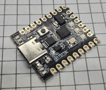
Mini RP2040 Developmentboard
Fazit: Alt, aber alles andere als nutzlos!
Ja, der ESP32 ist ein echtes Powerpaket. Ja, der Raspberry Pi Pico (RP2040) mischt kräftig mit und hat auch seinen Platz auf dem Basteltisch. Und ja – es gibt mittlerweile zig Alternativen mit WLAN, Bluetooth, Kamera, HID und noch viel mehr. Aber: Gerade das macht den guten alten Arduino so sympathisch: Er will gar nicht alles können – sondern einfach das, was man für viele kleine bis mittlere Projekte wirklich braucht. Ein Relais schalten? Ein paar LEDs blinken lassen? Einen Sensor auslesen und auf dem Display anzeigen? ➡️ Warum dafür einen Dual-Core mit WLAN bemühen, wenn es ein Nano für 3 € auch tut? Und genau das ist der Punkt: 🔹 Der Arduino ist einfach. 🔹 Er ist stabil. 🔹 Er hat eine riesige Community und viele erprobte Bibliotheken. 🔹 Er eignet sich perfekt zum Lernen – und bleibt auch danach oft die pragmatische Wahl. Gerade Anfänger profitieren enorm davon, sich nicht direkt mit komplexen Themen wie WiFi-Stack, Sleep-Modes oder USB-Treiberherausforderungen herumschlagen zu müssen. Und: Auch fortgeschrittene Bastler greifen gerne zum „alten Bekannten“, wenn es mal schnell, unkompliziert und robust sein soll. Mein Fazit: Der Arduino hat seinen festen Platz – auch im Jahr 2025. Nicht überall, aber da, wo „Keep it simple“ gefragt ist, ist er oft genau die richtige Wahl. ➡️ ESP32, RP2040 & Co. sind keine Gegner – sie sind Mitspieler im Team der Mikrocontroller. Die Kunst ist es, je nach Projekt den passenden Baustein auszuwählen. Jetzt bist du dran! Arbeitest du noch mit dem Arduino? Oder hast du komplett auf ESP32, RP2040 & Co. umgestellt? Welche Projekte hast du schon umgesetzt – und welcher Mikrocontroller war dafür die beste Wahl? 👉 Schreib es mir gerne in die Kommentare – ich freue mich auf den Austausch! Read the full article
0 notes
Text
Getting Started with Embedded Systems Programming

Embedded systems programming is the backbone of modern electronics. From smartwatches to washing machines, embedded systems power the intelligent functions of countless everyday devices. This guide will introduce you to the basics of embedded programming, key tools, and how to begin building your own embedded applications.
What is an Embedded System?
An embedded system is a computer integrated into a larger system or device, performing dedicated functions. Unlike general-purpose computers, embedded systems are designed for specific tasks, often with constraints on power, memory, and processing.
Examples of Embedded Systems:
Microcontrollers in home appliances
Sensor-based devices (e.g., temperature sensors, motion detectors)
Medical equipment
Automotive control systems
IoT (Internet of Things) gadgets
Core Components of an Embedded System
Microcontroller or Microprocessor: The brain of the embedded system (e.g., Arduino, STM32, ESP32).
Memory: RAM and ROM to store instructions and data.
Input/Output Interfaces: Connects to sensors, displays, motors, and communication modules.
Software: Custom firmware developed for specific functions, typically in C or C++.
Popular Programming Languages
C: Most widely used due to its efficiency and low-level hardware access.
C++: Used when object-oriented design is required.
Assembly: For highly optimized or time-critical routines.
MicroPython: Python for microcontrollers (e.g., ESP8266, Micro:bit).
Getting Started with Embedded Programming
Select Your Platform:
Beginners: Arduino (easy setup, wide community support)
Advanced: STM32, Raspberry Pi Pico, ESP32
Set Up Your Development Environment:
Install IDEs like Arduino IDE, PlatformIO, STM32CubeIDE
Download necessary drivers and board support packages
Write and Upload Code: Create simple programs like blinking an LED, then expand to sensors, displays, and communication modules.
Example: Blink an LED with Arduino
void setup() { pinMode(13, OUTPUT); // Set pin 13 as output } void loop() { digitalWrite(13, HIGH); // Turn LED on delay(1000); // Wait for 1 second digitalWrite(13, LOW); // Turn LED off delay(1000); // Wait for 1 second }
Tools and Debugging
Serial Monitor: For real-time debugging and logging.
Oscilloscope & Logic Analyzer: For electrical signal inspection.
In-Circuit Debuggers: Like JTAG or ST-Link for low-level debugging.
Best Practices
Write modular and readable code.
Use debouncing for physical inputs like buttons.
Handle memory carefully to avoid overflows.
Optimize power usage in battery-powered devices.
Conclusion
Embedded systems programming is both fun and powerful, offering endless possibilities for innovation in hardware and software. Whether you’re building a home automation project or diving into the world of IoT, understanding the basics of embedded programming gives you the foundation to create smart, responsive devices.
0 notes
Text
UHF Reader Based on Pico W & ESP32 with 50 Tags/Second Reading within 1.5 Meter Range

A UHF Reader (Ultra High Frequency Reader) is a device that is used to read and write data from UHF RFID tags within the 860MHz-960MHz frequency range. It is a multi tags 50 tags/second reading/writing device within 1-1.5 meter range designed with cutting edge UHF technology. It is a compact, portable and easy to use device.
The UHF reader has 2 variants: one is UHF Reader by Pico W and another is UHF Reader by ESP32. The Pico W variant comes with RP2040 microcontroller with Wi-Fi and BLE support. It is compatible with MicroPython, CircuitPython and Arduino for programming. ESP32 variant comes with ESP32 S3 series microcontroller and has 2.4GHz & Bluetooth 5 (LE) support. It is compatible with Arduino and Espressif IDE for programming.
Key Features and Specifications:
UHF Reader Pico Variant:

Powered by Raspberry Pi Pico W
RP2040 microcontroller dual-core Arm Cortex M0+ microprocessor with 264kB RAM
Supports Wi-Fi and BLE
1.14” TFT display for better visualization
Multi-tone buzzer for audio alerts
Micro USB Support for programming & Type C support for power
3 programmable buttons and Reset button
SD card slot for data storage/transfer
LED Status for power and battery charging
Multipurpose GPIOs breakout for interfacing external peripherals
SWD pins breakout for serial debugging
Supports MicroPython, CircuitPython, and Arduino for programming
UHF Reader ESP32 Variant:

Powered by ESP32 S3 WROOM-1
Dual-core 32 bit LX7 microprocessor with Up to 8 MB PSRAM and up to 16 MB flash memory
Supports 2.4GHz (802.11b/g/n) Wi-Fi and Bluetooth 5 (LE)
1.14” TFT display with ST7789 display driver
Comes with a Read and Write UHF module.
Frequency range of 865.1MHz-867.9MHz (for EU/UK) and 902.25MHz-927.75MHz (for US)
Can Identify 50 tags/second up to the 1.5-meter range.
TTL UART communication interface and communication baud rates 115200bps-38400bps
output power 18-26dBm and output power accuracy +/- 1dB
operation current 180mA at 3.5V (26 dBm Output), 110mA at 3.5V (18 dBm Output)
Multi-tone buzzer for audio alerts
2 user programmable buttons, Boot and Reset buttons
For power and programming support, the Type C Interface
SD Card slot for data transfer/storage
LED status for power and charging
Multipurpose GPIOs breakout for interfacing external peripherals
Supports Arduino and Espressif IDE for programming
By using ESP32 and RP2040, you can build a UHF RFID reader for scan tags and data tracking. This UHF Reader with ESP32 and Pico by SB Components is suitable for applications like warehouses, retail stores, and many other applications where you want to track your inventory data accurately.
#technology#innovation#tech#iot#rfid#uhf#uhf reader#arduino#espressif#iot applications#raspberry pi#rp2040#esp32#projects#programming#ultra high frequency reader#rfid tags#data tracking#electronics
1 note
·
View note
Text
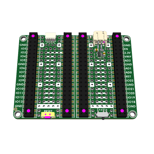
double your pleasure, double your fun, with double-proto-picobell
yesterday we made a single picobell prototyping underplate: plug your rp2040 pico into the double-headers to get a quick prototyping area plus labeled pins, stemma QT and a reset button. great for when you want to use our prototyping picobell (https://www.adafruit.com/product/5200), but want to go solder free. its a great match for the pre-soldered-header version of the Pico H (https://www.adafruit.com/product/5525) and Pico W H (https://www.adafruit.com/product/5544)
only thing better would be to double it up! this new design clone-tools the left side to the right, and connects all the pins through. this would let you plug in a pico on the left, and one of our picowbells - like say our Adalogger bell (https://www.adafruit.com/product/5703) - on the right. or swap locations, either way. since we dont need two reset buttons, we made the new half with an enable/disable switch connected to the EN pad of the pico to shut down the 3.3V buck. and since we don't need two QT ports either, we swapped that out for a battery JST PH port - hat tip to CoreElectronic's LiPo Expansion for the idea! (https://github.com/CoreElectronics/CE-PiicoDev-LiPo-Expansion-Board-for-Raspberry-Pi-Pico) Just like our Feathers, if you plug in a classic 3.7V Lipo battery the circuit will hot-swap over to it when the USB power is removed, and charge back up when the USB is re-inserted - there's two LEDs to let you know when the battery is charging and complete. there's also a jumper on the bottom if you want to disable charging, say cause you want to use an AA battery pack.
0 notes
Link
1 note
·
View note
Text
Raspberry Pi RP2040 MCU featuring the Quectel EG25-G 4G LTE cellular module in PicoCell 4g
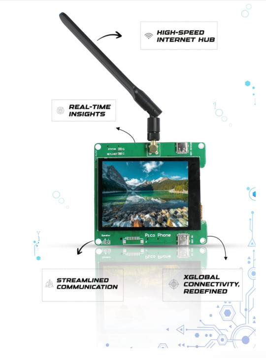
Introducing the revolutionary PicoCell 4G device, powered by the Raspberry Pi RP2040 MCU and featuring the Quectel EG25-G 4G LTE cellular module. In today’s world, where connectivity and innovation are key, this cutting-edge technology seamlessly combines the power of the RP2040 chip with the connectivity prowess of the Quectel EG25-G 4G LTE module. The PicoCell 4G is not your ordinary device; it transcends boundaries and redefines the way we connect, create, and communicate.
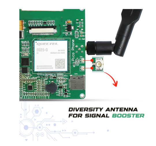
With its Multi-Constellation GNSS support, the PicoCell 4G can quickly and accurately determine your location, regardless of where you are. It acts like a bridge connecting people worldwide with call and messaging coverage that knows no borders. The EG25-G variant is like a world traveller, supporting a wide range of LTE FDD and TDD frequencies, UMTS options, and GSM. In simple terms, it keeps you connected no matter where you go. Are you seeking a dependable and swift wireless connection while on the move? Consider the PicoCell 4G as your solution. This adaptable device functions not only as a communication tool but also as a high-speed data server that supports technical features such as HTTP and TCP/IP. With the convenience of its dongle feature, you can enjoy lightning-fast LTE speeds of up to 150Mbps (DL) and 50Mbps (UL) while on the go. Essentially, it’s like having your high-speed internet connection that can be easily carried in your pocket. Perfect for the Tech-Enthusiast Attention tech enthusiasts!
The PicoCell 4G is specifically designed for M2M and IoT applications and acts like a superhero for connected devices, guaranteeing their optimal performance. It comes with a diverse antenna that provides a strong signal even in challenging situations. You can customize it to meet your specific needs with additional GPIO options. It is also energy-efficient, ensuring that it won’t run out of power when you need it the most. Furthermore, it features a status LED that offers real-time updates on network and satellite connections, making it easy to stay informed. It supports Quectel Enhanced AT Commands, which makes controlling your devices a breeze, ensuring that everything is effortless. Hello, the PicoCell 4G is a powerful device that caters to M2M and IoT applications with its exceptional features. It is powered by the plate number 1 chip with a 32-bit dual ARM Cortex-M0+ microcontroller and 8MB flash, and equipped with the Quectel EG25-G 4G LTE cellular module, supporting nano SIM cards. The device features dual Type C interfaces for programming and accessing the 4G module, a 3.2” Touch Display with a resolution of 320x240 pixels, driven by the plate number 2 Display Driver and plate number 3 capacitive touch controller. It comes in a range of vibrant RGB colours and offers additional GPIO options for peripheral connections. Furthermore, the device includes boot buttons for Pico, a power button for manually turning the 4G module on/off, an onboard microSD card for data logging, a battery connector with a charging circuit for portable use, a 3.5mm Audio Jack for headphones, and even includes speaker support for attaching a speaker. Additionally, the device provides indicator LEDs for board supply, module power, network status, and system status. The PicoCell 4G is an exceptional device optimized for M2M and IoT applications. It offers worldwide coverage and supports MIMO and DFOTA. With a multi-constellation GNSS receiver, you can track precise locations with ease. The 4G module supports various network bands and different speech codec modes. It has low power consumption for efficient operation and delivers LTE Max. 150Mbps DL/50Mbps UL data speeds. The PicoCell 4G is a game-changer that’s here to redefine the way we connect and create. Check out the Product Page and join the journey to experience connectivity without limits.
TO KNOW MORE : bit.ly/3RalKua
#PicoCell4G#WirelessWonder#ConnectAnywhere#MiniCellTower#CellularFreedom#PocketPower#4GOnTheGo#SignalSaver#StayConnected#MobileNetworkBoost
0 notes
Text
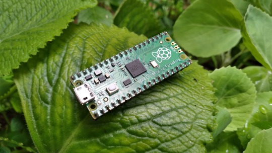
Uncovered Raspberry Pi Pico👇
Engineered by the Raspberry Pi company, the Raspberry Pi Pico stands as a distinctive microcontroller board within their range of offerings. In a manner akin to products like Arduino and ESP-32, the Pico was purposefully crafted for the management of electronic components, excelling in executing uncomplicated tasks within fundamental electronics projects, setting it apart from the comprehensive capabilities of a full-scale Raspberry Pi computer.
Unveiling the Essence of the Raspberry Pi Pico
The Raspberry Pi Pico emerges as a minimalist, economically-priced, and high-performance microcontroller board centered around the formidable RP2040 chip. Notably, the RP2040 constitutes an in-house microcontroller chip originating from Raspberry Pi Ltd., orchestrating the functionality of various other boards founded on the RP2040 architecture, alongside the Pico.
As the official RP2040 board from Raspberry Pi, the Pico boasts an embedded 2MB QSPI flash memory, catering to code writing and loading. Encompassing a total of 40 pins, the Pico offers seamless interaction with a diverse array of electronic components, with 26 of these pins assuming multifaceted roles as GPIO pins. A comprehensive exploration of the Raspberry Pi Pico's pinout is readily available for further scrutiny.
Diverse Iterations of the Raspberry Pi Pico board are on offer: the standard Pico (featuring unpopulated pin holes), the Pico H (with pre-soldered pin headers), the Raspberry Pi Pico W (equipped with Wi-Fi and Bluetooth capabilities), and the Pico WH (amalgamating wireless connectivity with pre-soldered headers).
Powering the Raspberry Pi Pico: A Deeper Insight
In contrast to its Raspberry Pi single-board computer counterparts, the Pico showcases a notably frugal power consumption profile. It demonstrates versatility in operation, sustaining voltage supply within the range of 1.8V to 5.5V DC. This adaptability enables utilization through either a 5V USB port on a computer or a pair of AA batteries, affording users the freedom to select their preferred power source. The Pico accommodates power input via both the micro-USB port on the board and GPIO pin 39 (VSYS), further amplifying its accessibility and ease of use.
1 note
·
View note
Text

@darquingdragon The idea is I want to try building a cat tracker... tracker? Yeah I know that sounds weird, let me try to explain.
My cat has this tracker device she wears that basically reads her GPS location every so often and then reports that to the internet via basically mobile phone networks in order to keep track of where she is and where she's been, effectively. Of course, with this being a pretty small device with limited battery capacity using only free GPS data, its accuracy is limited and sometimes the coverage for either GPS or phone networks can be a bit spotty. Also since her collar has a necessary emergency release mechanism in case it might get stuck on something, it's also something that she's had fall off on rare occasions.
Now to help facilitate better precision when attempting to locate either her or at least the tracker itself, it also supports Bluetooth Low Energy communication, albeit only over very short distances - problem is, the app for the tracker is ... not great at making use of the bluetooth feature? General bluetooth device finder apps do a much better job at it, but because the mobile app market being what it is, they're usually severely hampered by either ads or in-app purchases or both.
So. My plan is to take a bluetooth-enabled microcontroller like either the Raspberry Pi Pico W or an ESP32 or the like and see if I can basically make it just continuously scan for nearby bluetooth devices and report device names and signal strength, and also to lock a specific device as "main" to keep it listed even when out of contact. Basically make a kind of dedicated DIY gadget that can help me locate her tracker or any other bluetooth device in range, possibly also do the same kind of thing with wifi networks or devices or maybe even LoRa devices or whatever.
The plastic casing pictured above belongs to an IR thermometer that I bought for cheap with the explicit purpose of removing all its insides to make use of it for this very purpose - figure I'd use the display and button panel as an interface, stick a regular 18500 or 18650 lithium cell in the handle for power, and use a microcontroller to run it all as well as to scan for bluetooth stuff. In theory it should all be relatively simple stuff, I just need to decide what particular bits to put in it and see if I can get the tracking part working, heh.
so the thing I want is some kind of display module can fill at least most if not all of a 30 x 30 mm window while still fitting within the roughly 40 x 37 mm space, all while preferably being relatively simple to drive in terms of both power and data - bonus points for some kind of retro aesthetic like a monochrome dot matrix LCD but I'll take what I can get at this point.
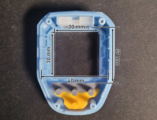


It's being a bother because most displays seem to be rectangular rather than square, and also have their PCB stick out a fair bit beyond the actual display area. Comically, many are also at least Hi-Color displays which take more processing to drive due to a greater amount of data needing to be pushed compared to a simple single colour where every pixel is either on or off.
All I really need to display is like battery status, signal strength, and optionally the ability to switch between found devices and/or networks...
10 notes
·
View notes
Text
Raspberry Pi Pico: Vale a pena aprender?
Aprenda como usar todos os periféricos do Raspberry Pi Pico, Como instalar bibliotecas no Thonny IDE e ainda veja um comparativo do Pico/Pico W com ESP32, tudo em um único post. Mais completo que isso somente o datasheet.
O Raspberry Pi Pico desde o lançamento vem sendo muito desejado por muitos projetistas, mas será que realmente vale a pena aprender? Neste post você vai aprender tudo sobre ele. 1 Surgimento do Raspberry Pi Pico Quem acompanha a empresa Raspberry Pi, sabe que todos seus lançamentos tem um preço base para um determinado produto e o propósito disso é democratizar ao máximo o acesso aos produtos…
Ver no WordPress
#arduino nano vs raspberry pi pico#arduino raspberry pi pico i2c#arduino vs raspberry pi pico#como programar raspberry pi pico#pico raspberry pi#raspberry pi pico#raspberry pi pico adc#raspberry pi pico analog to digital#raspberry pi pico battery#raspberry pi pico datasheet#raspberry pi pico documentation#raspberry pi pico especificações#raspberry pi pico examples#raspberry pi pico pinout#thonny raspberry pi pico
1 note
·
View note
Text
I have the power to make a music box with Butch 4 Butch as the song but I lack some resources and a gf
#I have a Raspberry Pi Pico and the programming for the song i lack some better speakers; a battery and the box#i could also get another component to make it sound like a music box and not like an old nokia phone#i have no money but many ideas#buy griangotchi
5 notes
·
View notes
Text

I love those flip style clocks, like the one from Groundhog Day. Why? I'm not sure exactly, they're just very cool looking and fit into that facinating retro futuristic electromechanical niche.
We've got one of these at home to show the time and date. The clock is just a standard quartz rotary type, but the day name, day number and month use flippers.
After years of faithful service our clock started to fail at triggering the flippers. After cracking it open I determined it was due to the clock failing to send the flip signal at 12 o'clock.
I decided to put my new Raspberry Pi Pico microcontroller into action by creating a pacemaker!

An LCD screen allows the current time which is set when power is connected

Then at midday and midnight it triggers a relay that activates the flipper mechanism in the clock

Currently it's got a fairly high power draw, which I plan to reduce using longer sleep periods on the Pico. Also I'll remove the LEDs from the relay and turn off the LED light on the LCD.
I've ordered a Li-ion battery pack and charger which I'll be attaching and then fitting the whole thing into the clock.
It's been a great project to work on this and it's not over yet. It's amazing such a cheap little board as the Pico is capable of such useful things. Love it!
1 note
·
View note
Text
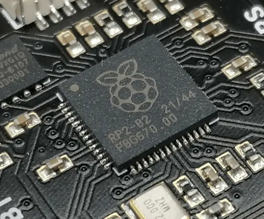
Ein erster Blick auf den Melopero Cookie RP2040: Raspberry Pi Pico meets micro:bit
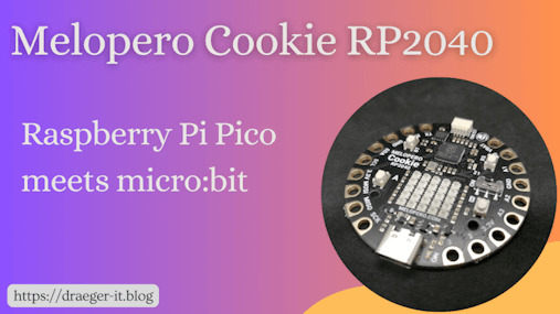
In diesem Beitrag möchte ich mit dir zusammen einen ersten Blick auf den Melopero Cookie RP2040 werfen. Dieser Mikrocontroller ist ein Mix aus Raspberry Pi Pico, BBC micro:bit und auch der Calliope Mini findet sich irgendwie hier wieder.

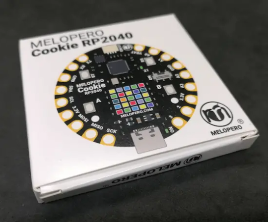
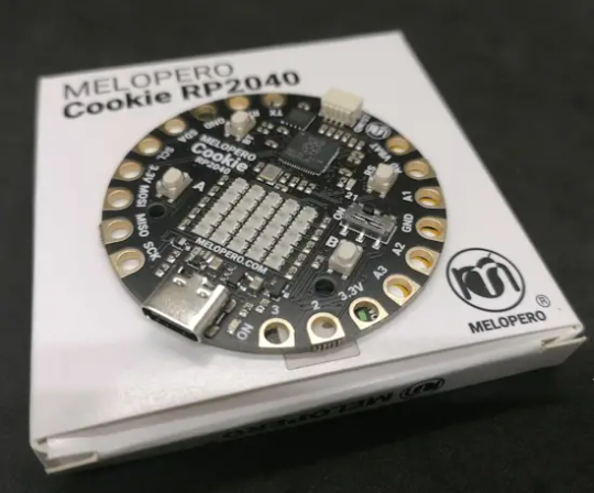
Diesen Mikrocontroller habe ich im Onlineshop von Botland.de für knapp 16 € zzgl. Versandkosten erstanden. In diesem Shop bekommst du diesen Mikrocontroller derzeit zum besten Preis.
Warum noch ein Klon?
Die große Frage, welche man sich zunächst stellen kann, ist "Warum noch ein Klon?". Diese Frage ist berechtigt, denn, dieser Mikrocontroller mit dem RP2040 Chip, einigen Anschlüssen und einer LED-Matrix ist jetzt nicht das neueste und bringt auch nicht soviel zusätzlichen Spaß. Theoretisch könnte hier der Beitrag enden, jedoch möchte ich diesem eine Chance geben und einmal ins Detail schauen.
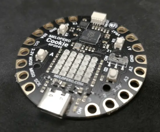
Pins & Anschlüsse
Vor allem, wenn man sich das Format etwas genauer betrachtet, dann finden wir die Pins rings um den Mikrocontroller angeordnet, welche man mit Krokodilklemmen oder Bananenstecker (3 mm) abgreifen kann.
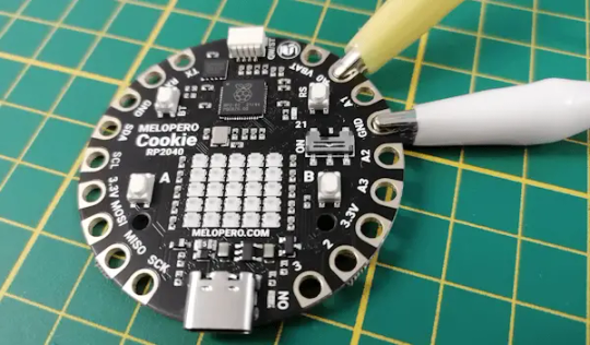
Batterieanschluss & USB-C Schnittstelle
Am Mikrocontroller findest du den Pin VBAT über diesen kannst du deinen Mikrocontroller via Batterie zu betreiben. Der Hersteller gibt hier an, dass die gleichzeitige Verwendung beider Stromanschlüsse dazu führen kann, dass entweder deine Batterie oder dein PC zerstört werden kann. Ich würde sogar so weit gehen, dass eher der Mikrocontroller zerstört wird!
Features des Melopero Cookie RP2040
Der Mikrocontroller bietet wie erwähnt einige Features, welche wir bei anderen bereits finden. Zu diesen Features zählen: - eine 5x5 RGB LED Matrix, - zwei Taster, - eine USB-C-Schnittstelle, - einen Qwii-Anschluss, - Kontakte Abgreifbar via Krokodilklemme& Bananenstecker, - zwei Löcher zur Montage Abmaße des Mikrocontrollers sind Ø 50,8 mm. Technische Daten des RP2040 Chips Verbaut ist ein RP2040 Chip von der Raspberry Pi Foundation, welcher nachfolgenden technischen Daten hat: MikrochipRP2040, Dual-Core Arm Cortex M0+ mit bis zu 133 MHzSpeicher SRAM264 KBFlash2 MBSchnittstellenUSB 1.1 2x SPI, 2x I²C, 2x UART 3x 12-bit ADC (Analog Digital Converter)En/Ausgänge26 Pins 16x PWM ChannelSensoren & AktorenTemperatursensor Timer
Pinout & Aufbau des Melopero Cookie RP2040
Auf dem Mikrocontroller findest du diverse Aktoren, welche du recht einfach programmieren kannst. Die LED ist als einzige von diesen mit "21" beschriftet.
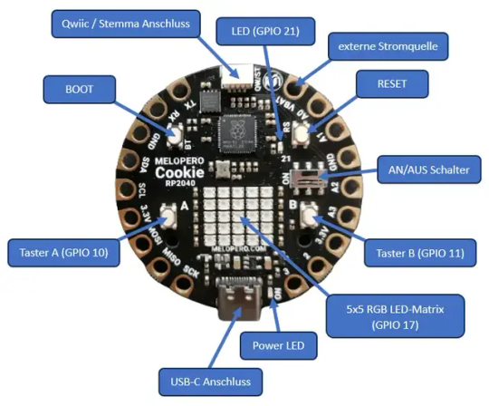
Aufbau des Melopero Cookie RP2040 Qwiic / Stemma Anschluss Über den Qwiic / Stemma Anschluss kannst du spezielle Sensoren und Aktoren in Reihe schalten und einzeln adressieren. Die Kommunikation läuft dabei über I2C. Jedoch sind derzeit die Sensoren & Aktoren für dieses Ökosystem recht teuer, sodass sich ein Wechsel, nach meiner Meinung noch nicht lohnt.
Einrichten und Programmieren des Melopero Cookie RP2040
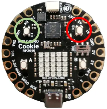
Wie üblich, kannst du deinen Mikrocontroller in MicroPython, CircuitPython sowie in der Arduino IDE programmieren. Ich möchte im Nachfolgenden den Mikrocontroller in MicroPython programmieren. https://youtu.be/3M3b8clU-FU Der Hersteller hat zu diesem Mikrocontroller eine offizielle, englische Dokumentation bereitgestellt, wo gezeigt wird, wie dieser geflasht und für MicroPython eingerichtet wird. Flashen des Mikrocontrollers für MicroPython Das Flashen des Melopero Cookie RP2040 für MicroPython ist sehr einfach, unterscheidet sich jedoch deutlich vom Raspberry Pi Pico. Denn man muss bei verbundenem Gerät die Taste "BT" (grüner Kreis) & "RS" (roter Kreis) drücken und die Taste "RS" loslassen, dann wird das Laufwerk eingebunden und wir können die Taste "BT" loslassen. Also eigentlich sehr einfach.
Wenn das Laufwerk eingebunden ist, dann musst du nun die entsprechende UF2-Datei mit der neuen Firmware auf diesen kopieren. Die Firmware bekommst du unter http://www.melopero.com/Melopero_Cookie_RP2040.zip. In der ZIP-Datei findest du die Firmware für CircuitPython und MicroPython sowie eine Bibliothek mit Beispielen für C++.
Programmieren in der Thonny IDE
Den Mikrocontroller kannst du nach dem Flashen dann zum Beispiel in der Thonny IDE programmieren. Dazu musst du zunächst den Interpreter einrichten.
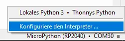
Im Programm klickst du unten rechts auf den derzeit ausgewählen Mikrocontroller und wählst aus dem Menü "Konfiguriere den Interpreter ...".
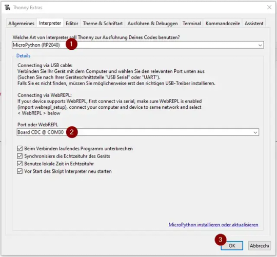
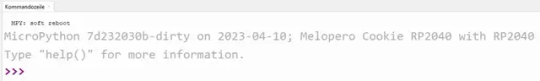
Im neuen Dialog wählst du dann als Erstes den Eintrag "MicroPython (RP2040)" (1) aus. Danach den Port (2). Solltest du mehrere serielle Geräte an deinem PC angeschlossen haben, so schaue einmal in den Geräte-Manager, um den passenden zu finden. Die Auswahl bestätigen wir mit der Schaltfläche "OK" (3). Wenn du nun in der Taskleiste auf die Schaltfläche "Stopp/Restart ausführen" klickst, dann sollte in der Kommandozeile die nachfolgende Ausgabe erscheinen.
Programmieren der Taster & LED
Wie oben gezeigt findest du auf dem Mikrocontroller zwei Taster und eine kleine SMD LED. Als erstes möchte ich dir zeigen, wie diese programmiert wird. Mit den Tastern A & B möchte ich zunächst die LED AN & AUS schalten. #aus dem Modul machine die Klasse Pin laden from machine import Pin #Modul time importieren import time #die LED ist am GPIO 21 angeschlossen #und wird als Ausgang definiert led = Pin(21, Pin.OUT) #die Taster sind an den GPIOs 10 & 11 #angeschlossen und werden als Eingang #definiert buttonA = Pin(10, Pin.IN) buttonB = Pin(11, Pin.IN) #starten einer Endlosschleife while True: #Wenn der Taster A gedrückt wird, dann... if buttonA.value() == 1: #LED aktivieren led.on() #einlegen einer kleinen Pause, #damit entprellen wir den Taster time.sleep(0.5) #Wenn der Taster B gedrückt wird, dann... if buttonB.value() == 1: #LED deaktivieren led.off() #einlegen einer kleinen Pause, #damit entprellen wir den Taster time.sleep(0.5) Wenn wir den Code auf dem Mikrocontroller ausführen, dann können wir mit den beiden Tastern die kleine SMD LED Ein- und Ausschalten.
Programmieren der 5x5 RGB LED Matrix
Mit der Firmware zu MicroPython bekommst du Module zum Abfragen der Taster sowie für die RGB LED-Matrix. Diese Module müssen nicht zusätzlich installiert werden und du brauchst diese lediglich importieren und kannst diese verwenden. Für die Programmierung der 5x5 RGB LED-Matrix hast du fertige, kleine Funktionen um entweder einzelne LEDs anzusteuern oder auch Scrolltext auf dieser auszugeben. Das finde ich besonders gut gelungen. #Importen der Klasse Cookie_RP2040 aus dem Modul melopreo_cookie from melopero_cookie import Cookie_RP2040 #Text für den Scrolltext msg = "Hallo Welt!" #erzeugen eines Objektes vom Typ Cookie_RP2040 cookie=Cookie_RP2040() #LEDs löschen cookie.clear_screen() #setzen der Textfarbe als RGB Wert #Der letzte Wert bildet die Helligkeit ab! cookie.set_rgb_color(0, 0, 255,0.05) #setzen der Hintergrundfarbe cookie.set_rgb_background(0,0,0, 0.1) #anzeigen / abspielen des Scrolltextes cookie.show_message(msg) Mit diesem kleinen Code erzeugen wir nun die Laufschrift "Hallo Welt!" auf der LED-Matrix. Die Farbe für den Text habe ich in Blau gesetzt. Read the full article
0 notes
Text
Ist das endlich die Lösung für alle unsere Pico Probleme?
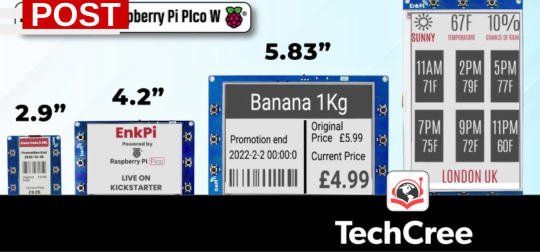
EnkPi Boards werden derzeit auf kickstarter ausgelobt und könnten viele unserer Probleme in verbindung mit dem Raspberry Pi Pcio/Pico W lösen.
Alle Infos zu den verschiebenen eInk Boards sind derzeit auf der Kickstarter Projekt Website zu finden. Wer etwas Mut hat und das Kickstarter Risiko kennt könnte hier etwas ganz tolles bekoommen. Warum? Es gibt über einen Raspberry Pi Pico und auch den Pico W eigentlich nicht viel zu bemängeln. Es ist ein oder das günstige Entwicklerboard aus dem Hause der Raspberry Pi Foundation UK. Es dürfte kaum einen Tüftler geben, der nicht von seinem Pico oder Pico W schwärmtt. Der Microcontroller erlaubt uns schließlich bereits in der Grundausstattung schon die Realisierung vieler Projekte.
Und seit dem die Pico Variante mit auf der Platine verbautem WLAN Modul am Marktt ist, dann nennt sich der Pico eben Pico W, hat dieses preiswerte kleine Teil sicher nochmals an Attraktivität zugenommen. Allerding gibt es immer noch ein paar Themen die sich nach wie vor als etwas hinderlich, ja nachteilig herausstellen. Eines der Themen wäre da bspw., dass der Pico W zwar über eine RTC (Real Time Clock) verfügt, sich aber mangels einer Onboard Batterie ohne Stromversorgung die Zeit schlicht nicht merken kann.
Und auch das mit dem WLAN ist so eine Sache. Zwar ist es kein Problem über die Thonny IDE (Entwickler-Software für Python) einen Pico W zu programmieren und zu betanken. Auch lässt sich das Script für den Betrieb als Mini-Webserver ausführen und man erhält dann auch die ihm zugewiesene IP Adresse unter der die Website des Picos aufrufbar ist. Ohne die IDE aber können wir einen Pico nicht in einem WLAN zuordnen oder gar die IP Adresse uns anzeigen lassen. Was fehlt ist ein Display. Und es fehlen ein paar Knöpfe mit denen man ggf. eine WLAN Anmeldung per Push-Methode oder gar über Eingaben umsetzen könnte.

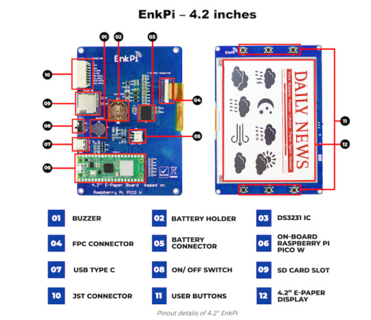
Jetzt könnte das EnkPi ändern. Zwar gibt es bereits viel Zubehör für den Raspberry pico und Pico W, doch diese Boards mit eInk Display haben noch mehr auf der Platine verbaut. Da wäre ein Buzzer, eben der so fehlende Batteriehalter für bspw. die RTC Funktionoder gar ein SD Karten Slot. Das und noch etwas mehr. Zudem soll das Board, welches es mit eInk Display in vier größen geben soll unter anderem auch Micropython programmierbar sein. Und das wäre ein echter Hit.
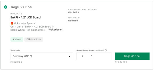
Das hört sich fats schon zu gut an. Wer sich traut dieses Projekt zu unterstützen kann dann im Mär 2023 ggf. schon sein EnkPi bekommen. So jedenfalls wird dies aktuell angeboten. Allerdings ist der Preis derzeit recht hoch. Gut es sind viele Bauteile verbaut und wenn das Display Board leistet was wir uns davon erhoffen, mag sein es könnte halbwegs gerechtfertigt sein. Am Beispiel eines 4.2" LCDEnkPi Borads wäre das inkl. Versand nach Deutschland immerhin satte 84 Euro. Sehr viel Geld ist das bei aller Liebe schon.
Andere köcheln derzeit auch an solchen Lösungen und persönlich hoffe und vermute ich auch stark, dass wir in Kürze von Pimoroni etwas genau in diese Richtung hören werden. Alles andere würde mich wundern. Allerdings dürfte noch interessant sein, dass bei Micropython gerade das eInk und das Thema PicoW Anmeldung in einem WLAN ohne IDE ein offenes Thema ist. Es wird zwar daran gearbeitet, doch mir ist derzeit völlig unklar wie EnkPi das bereits für Microphython gelöst haben will.
0 notes
Text
PiSquare: RP2040 & ESP-12E-based board for all Raspberry Pi HATs
PiSquare is a compact, wireless communication board designed for Raspberry Pi that enables you to wirelessly connect and communicate with multiple Raspberry Pi HATs including SPI, I2C, and SPI HATs. It is based on two powerful components:
⦁ The RP2040 microcontroller (the same chip used in the Raspberry Pi Pico). ⦁ The ESP-12E Wi-Fi module for seamless wireless communication.
By using socket programming, PiSquare can wirelessly interact with Raspberry Pi HATs through TCP/IP communication, allowing you to connect as many devices as you need, without worrying about physical stacking or GPIO conflicts.
Key Specifications:
⦁ Microcontroller: Raspberry Pi RP2040
Core Architecture: Dual-core ARM Cortex-M0+ microcontroller
Clock Speed: Up to 133 MHz
Flash Memory: 2MB onboard QSPI Flash (for program storage)
RAM: 264KB SRAM
GPIO Pins: 26 multi-function GPIO pins with support for PWM, SPI, I2C, UART, and other peripherals
⦁ Wi-Fi Connectivity: ESP-12E
Wi-Fi Standard: 802.11 b/g/n
Wireless Frequency: 2.4 GHz
Wi-Fi Chipset: ESP8266 (with 4MB of onboard Flash)
Data Rate: Up to 72.2 Mbps (with 802.11n support)
Communication Interface: UART (Universal Asynchronous Receiver Transmitter)
⦁ Wireless Communication via Socket Programming
Protocol: TCP/IP (Transmission Control Protocol/Internet Protocol) via socket programming
Connection Type: Full-duplex, bi-directional communication
Network Type: Local Area Network (LAN) or Wi-Fi based network for device communication
Number of Supported Devices: Configurable for communication with multiple (n) Raspberry Pi HATs over Wi-Fi without the need for physical stacking
Socket Layer: Raw socket-based communication for sending and receiving data over the network
⦁ HAT Compatibility
Supported Protocols: SPI (Serial Peripheral Interface): Full-duplex, synchronous communication for connecting peripherals
I2C (Inter-Integrated Circuit): Multi-master, multi-slave communication for sensors, actuators, and peripheral devices
GPIO-based HATs: Supports a variety of devices and sensors with GPIO pin control
Pin Multiplexing: Flexible I/O pin assignment allowing for easy configuration of multiple communication protocols simultaneously
Addressing: Supports unique addressing for SPI and I2C devices to avoid conflicts
⦁ Power Supply
Voltage: 5V DC ±5% (typical operating voltage range)
Power Consumption: Low-power operation suitable for remote or battery-powered applications
Regulation: Onboard linear voltage regulator to provide stable power for the microcontroller and Wi-Fi module
⦁ Form Factor
Dimensions: 65mm x 30mm x 20mm (compact design suitable for integration into small devices)
Mounting: Compatible with standard Raspberry Pi connectors (via external interface) without the need for physical GPIO stacking
⦁ I/O and Expansion
Interface: UART, SPI, I2C (for communication with external peripherals)
GPIO: 26 GPIO pins for signal input/output, including support for digital, analog, PWM, and interrupts
Use Cases
Here are a few ways PiSquare can revolutionize your Raspberry Pi projects:
Multi-HAT Robotics: Easily connect multiple HATs for motor control, sensor arrays, and communication modules in a wireless setup.
IoT Projects: PiSquare can communicate with several sensor HATs in remote locations, sending data back to a central Raspberry Pi for processing or cloud storage.
Home Automation: Connect a variety of home automation HATs wirelessly, creating a smart home system that’s efficient and scalable.
Distributed Sensor Networks: Set up multiple sensors across a large area without worrying about physical connections or pin conflicts.
The Pisquare RP2040 with the onboard ESP-12E Wi-Fi module is a powerful and compact solution for anyone looking to build wireless IoT projects. Its support for multiple HATs, including SPI and I2C, makes it versatile enough to handle a wide variety of peripherals, while its ability to implement socket programming provides you with the flexibility to create robust networked applications.
Whether you're creating a smart home system, an industrial IoT device, or a robotics project, the Pisquare by SB Components can be the perfect foundation for your next creation.
#technology#raspberry pi#innovation#tech#techinnovation#programming#tech projects#projects#artificial intelligence#technews
0 notes