#Computer Requirements for CAD Software
Explore tagged Tumblr posts
Visit Tumblr Blog
Explore Tumblr blogs with no restrictions, modern design and the best experience.
Last Seen Tumblr Blogs


Fun Fact
Total funding amounts to $125.3M.
Text
Understanding CAD Computer Requirements: Essential Guide for Optimal Performance
If you’re diving into the world of Computer-Aided Design (CAD), ensuring that your system is properly equipped to handle the demands of software like AutoCAD is crucial. Whether you are an architect, engineer, or designer, having the right hardware and software configuration will not only improve your workflow but also guarantee smoother performance and better results. In this blog, we’ll walk through the key computer requirements for running AutoCAD and other CAD software smoothly.
Why Understanding CAD Computer Requirements Matters
Running CAD software efficiently requires more than just having a standard computer. CAD applications, especially AutoCAD, are resource-intensive and demand high computing power. Without a suitable setup, you might experience lagging, crashes, or long rendering times that could affect productivity. Understanding these requirements ensures that your system is up to the task and can handle the software’s robust functionalities without compromising performance.
Key CAD Computer Requirements for Optimal Performance
1. Processor (CPU): The Brain of Your CAD System
The processor is the heart of your CAD system. CAD software requires a multi-core processor to handle complex calculations and data. AutoCAD, for example, performs better on processors that can handle multiple tasks at once.
Recommended: A multi-core processor, ideally with 4 or more cores, such as Intel i7/i9 or AMD Ryzen 7/9.
Minimum: Intel Core i5 or AMD Ryzen 5 (6th generation or newer).
Choosing a higher-end processor will significantly enhance your CAD experience, especially when working with complex designs or large files.
2. Graphics Card (GPU): Visuals and Rendering Performance
The graphics card is crucial for rendering 3D models and visualizing designs in AutoCAD. A powerful GPU will ensure smooth navigation, rendering, and model manipulation in both 2D and 3D spaces.
Recommended: NVIDIA GeForce RTX Quadro series or AMD Radeon Pro series.
Minimum: NVIDIA GeForce GTX or AMD Radeon RX series.
For demanding 3D modeling tasks, consider upgrading to a workstation-grade GPU like the NVIDIA Quadro series, which is optimized for professional CAD workflows.
3. Memory (RAM): Smooth Multitasking
When working with large files or running multiple applications, ample RAM is necessary to avoid system slowdowns or crashes. CAD software requires significant memory to store large drawings, 3D models, and complex calculations.
Recommended: 16GB or more of RAM.
Minimum: 8GB of RAM.
For more intensive CAD tasks or multitasking (like running AutoCAD with other software), investing in 32GB or more of RAM is ideal.
4. Storage: Quick Access to Large Files
CAD designs often involve large files that need fast access and ample storage space. A slow hard drive can create bottlenecks when loading files or saving work, hindering your productivity. Opting for an SSD (Solid-State Drive) will significantly improve file loading times and overall system responsiveness.
Recommended: 512GB or higher SSD for storage.
Minimum: 256GB SSD or a 1TB HDD (though SSD is always recommended).
For the best performance, SSDs should be used for the operating system and primary software installation, while larger HDDs can be used for archival purposes.
5. Display: Crisp and Accurate Visualization
A high-resolution display is essential for accurately visualizing detailed designs and models. AutoCAD users often work with intricate 2D and 3D elements, making a large, high-resolution monitor an essential component of the setup.
Recommended: A 24” or larger screen with 1920x1080 resolution (Full HD) or higher, ideally with IPS technology for better color accuracy.
Minimum: 21” screen with 1920x1080 resolution.
For better productivity, you may even consider a dual monitor setup to increase workspace and improve multitasking efficiency.
6. Operating System: AutoCAD Compatibility
The operating system you use can impact the compatibility and performance of your CAD software. AutoCAD supports both Windows and macOS, but Windows remains the dominant platform for CAD applications due to better driver support and compatibility.
Recommended: Windows 10 64-bit (or newer), or macOS Mojave 10.14 or later.
Minimum: Windows 8.1 (64-bit) or macOS High Sierra 10.13 or later.
For those using Windows, make sure to keep your OS updated to take advantage of the latest performance and security enhancements.
7. Internet Connection: Cloud Integration and Updates
While not a direct hardware requirement, a reliable internet connection is important for downloading software updates, using cloud-based storage, and collaborating on projects. AutoCAD’s cloud integration features, such as AutoCAD Web and AutoCAD Mobile, rely on internet connectivity for seamless operation.
Recommended: Stable broadband connection with speeds of at least 10 Mbps.
Minimum: Basic internet connection for updates and cloud features.
Additional Tips for Optimizing Your CAD System
Ensure Regular Software Updates: Keeping your AutoCAD software and drivers up to date ensures compatibility and optimizes performance.
Consider External Storage for Backup: Large CAD files can quickly fill up your system’s storage, so having an external drive or cloud storage option for backup and archiving is a good idea.
Use CAD-Specific Peripherals: A high-quality mouse and keyboard designed for CAD work can enhance precision and reduce strain during long working hours.
Conclusion
Setting up a system to run AutoCAD and other CAD software efficiently isn’t just about meeting the bare minimum requirements — it’s about ensuring that your system can handle complex design tasks without compromising on speed or performance. By investing in a high-performance processor, powerful graphics card, sufficient RAM, and an SSD for fast storage, you’ll experience smoother, more efficient CAD workflows.
To learn more about AutoCAD system requirements, be sure to check out Virto Solar’s AutoCAD System Requirements page. This guide will help you make the right decisions for your setup, ensuring that your CAD design work is always at its best.
Are you ready to upgrade your system for seamless CAD experiences? Make sure your system is optimized for success with the right components, and get started on your next project with confidence!
#AutoCAD System Requirements#Best Computer for AutoCAD#AutoCAD Hardware Requirements#Computer Requirements for CAD Software#Optimal PC for AutoCAD#CAD System Configuration#CAD Design Computer Specifications#Best Graphics Card for AutoCAD#Recommended Processor for AutoCAD#AutoCAD RAM Requirements#Storage Requirements for AutoCAD#AutoCAD Performance Optimization#How to Choose a Computer for AutoCAD#AutoCAD PC Setup Guide#Best Workstation for AutoCAD#AutoCAD Compatible Hardware#Laptop for AutoCAD#Solid-State Drive for AutoCAD#AutoCAD 3D Modeling Requirements#AutoCAD 2025 System Requirements#How Much RAM for AutoCAD#Best Monitor for CAD Design#AutoCAD Operating System Requirements#AutoCAD Graphic Cards Comparison
0 notes
Note
Amy tips for getting 30 prebuilt pcs for 1500$ each
We're going to play a game where I show tumblr what I do at work by doing it on tumblr. You can answer my questions in successive anonymous asks. My responses to you will be bracketed by dashed lines, with instructions and commentary before and after.
---------------------------
Hi Anon!
I can definitely help you with your desktop needs. Can you tell me whether you're looking minimize your costs, or get the maximum amount of computer that I can get you for a per-unit price of $1500?
Here are some details that will help me narrow down options that are a good fit for your situation:
Very generally, what will these be for? Basic office use (browsing, office suite)? Video Production? CAD? Finance? Medical providers? Educators?
What date are you looking to have these machines in place?
Is there a specific type of software that you know will be installed on these devices, and if so can you get me the hardware specs required by the software vendor?
Please let me know if you've got any questions, or if there is anything that I can do for you.
Thanks! - Ms-D
-----------------------------
The average cost of business desktops that I sell at work is $700-$900; these are devices that I would give an anticipated lifespan of 7 years, with hardware upgrades planned at 5 years. This is for a mid-range desktop with a 3-year next business day onsite warranty, no software, and does not include the cost of tax, shipping, or configuration. The cost of labor can come close to the cost of the machine for configuration. If I were *PERSONALLY* deploying these machines (pulling them out of the box, debloating, creating profiles, installing software, reboxing, transporting to the site, installing and connecting to peripherals) I'd probably charge around $200-300 per device. My work charges a lot more. Because of that, a 1500 computer is quite likely to be a 700 computer with three hours of estimated labor. If you've got an in-house IT department and aren't going to be paying through the nose for setup, you can get *a lot* of business-class computer for $1500.
If someone at work asked me for a $1500 computer, I would assume that was the cost of the machine ONLY, no peripherals, no configuration, no installation, no software, though I would try to consider both tax and our markup and would look for devices that would maximize performance while under-but-close-to the mark. If I found something that was slightly over (say by up to $70), I would drop our markup to get closer to the client's budget.
What this means for YOU, the computer consumer, is that when you're looking at a computer you need to consider the following in your budget, NOT just the sticker price.
Computer Cost
Software Cost
Setup Cost (if you're not doing it yourself)
Shipping Cost
Tax
Peripherals (computers almost all come with a mouse and a keyboard, these are usually inexpensive but very sturdy; if you want a nice keyboard and an ergonomic mouse you have to buy your own)
Whether you will LOSE peripherals when you replace your current device - do you need to buy an external optical disk drive if your old machine had a CD drive but the new machine doesn't?
Those things can add hundreds of dollars to your total cost, so figure out how much that will be so that you can figure out what your ACTUAL budget for your computer is.
(Also your computer shouldn't be plugged directly into the wall; if you're getting ready to replace a machine and you don't already own a desktop UPS, a desktop UPS should be part of the cost of your next machine!)
118 notes
·
View notes
Text
CNC development history and processing principles

CNC machine tools are also called Computerized Numerical Control (CNC for short). They are mechatronics products that use digital information to control machine tools. They record the relative position between the tool and the workpiece, the start and stop of the machine tool, the spindle speed change, the workpiece loosening and clamping, the tool selection, the start and stop of the cooling pump and other operations and sequence actions on the control medium with digital codes, and then send the digital information to the CNC device or computer, which will decode and calculate, issue instructions to control the machine tool servo system or other actuators, so that the machine tool can process the required workpiece.

1. The evolution of CNC technology: from mechanical gears to digital codes
The Beginning of Mechanical Control (late 19th century - 1940s)
The prototype of CNC technology can be traced back to the invention of mechanical automatic machine tools in the 19th century. In 1887, the cam-controlled lathe invented by American engineer Herman realized "programmed" processing for the first time by rotating cams to drive tool movement. Although this mechanical programming method is inefficient, it provides a key idea for subsequent CNC technology. During World War II, the surge in demand for military equipment accelerated the innovation of processing technology, but the processing capacity of traditional machine tools for complex parts had reached a bottleneck.
The electronic revolution (1950s-1970s)
After World War II, manufacturing industries mostly relied on manual operations. After workers understood the drawings, they manually operated machine tools to process parts. This way of producing products was costly, inefficient, and the quality was not guaranteed. In 1952, John Parsons' team at the Massachusetts Institute of Technology (MIT) developed the world's first CNC milling machine, which input instructions through punched paper tape, marking the official birth of CNC technology. The core breakthrough of this stage was "digital signals replacing mechanical transmission" - servo motors replaced gears and connecting rods, and code instructions replaced manual adjustments. In the 1960s, the popularity of integrated circuits reduced the size and cost of CNC systems. Japanese companies such as Fanuc launched commercial CNC equipment, and the automotive and aviation industries took the lead in introducing CNC production lines.
Integration of computer technology (1980s-2000s)
With the maturity of microprocessor and graphical interface technology, CNC entered the PC control era. In 1982, Siemens of Germany launched the first microprocessor-based CNC system Sinumerik 800, whose programming efficiency was 100 times higher than that of paper tape. The integration of CAD (computer-aided design) and CAM (computer-aided manufacturing) software allows engineers to directly convert 3D models into machining codes, and the machining accuracy of complex surfaces reaches the micron level. During this period, equipment such as five-axis linkage machining centers came into being, promoting the rapid development of mold manufacturing and medical device industries.
Intelligence and networking (21st century to present)
The Internet of Things and artificial intelligence technologies have given CNC machine tools new vitality. Modern CNC systems use sensors to monitor parameters such as cutting force and temperature in real time, and use machine learning to optimize processing paths. For example, the iSMART Factory solution of Japan's Mazak Company achieves intelligent scheduling of hundreds of machine tools through cloud collaboration. In 2023, the global CNC machine tool market size has exceeded US$80 billion, and China has become the largest manufacturing country with a production share of 31%.
2. CNC machining principles: How code drives steel
The essence of CNC technology is to convert the physical machining process into a control closed loop of digital signals. Its operation logic can be divided into three stages:
Geometric Modeling and Programming
After building a 3D model using CAD software such as UG and SolidWorks, CAM software “deconstructs” the model: automatically calculating parameters such as tool path, feed rate, spindle speed, and generating G code (such as G01 X100 Y200 F500 for linear interpolation to coordinates (100,200) and feed rate 500mm/min). Modern software can even simulate the material removal process and predict machining errors.
Numerical control system analysis and implementation
The "brain" of CNC machine tools - the numerical control system (such as Fanuc 30i, Siemens 840D) converts G codes into electrical pulse signals. Taking a three-axis milling machine as an example, the servo motors of the X/Y/Z axes receive pulse commands and convert rotary motion into linear displacement through ball screws, with a positioning accuracy of up to ±0.002mm. The closed-loop control system uses a grating ruler to feedback position errors in real time, forming a dynamic correction mechanism.
Multi-physics collaborative control
During the machining process, the machine tool needs to coordinate multiple parameters synchronously: the spindle motor drives the tool to rotate at a high speed of 20,000 rpm, the cooling system sprays atomized cutting fluid to reduce the temperature, and the tool changing robot completes the tool change within 0.5 seconds. For example, when machining titanium alloy blades, the system needs to dynamically adjust the cutting depth according to the hardness of the material to avoid tool chipping.


3. The future of CNC technology: cross-dimensional breakthroughs and industrial transformation
Currently, CNC technology is facing three major trends:
Combined: Turning and milling machine tools can complete turning, milling, grinding and other processes on one device, reducing clamping time by 90%;
Additive-subtractive integration: Germany's DMG MORI's LASERTEC series machine tools combine 3D printing and CNC finishing to directly manufacture aerospace engine combustion chambers;
Digital Twin: By using a virtual machine tool to simulate the actual machining process, China's Shenyang Machine Tool's i5 system has increased debugging efficiency by 70%.


From the meshing of mechanical gears to the flow of digital signals, CNC technology has rewritten the underlying logic of the manufacturing industry in 70 years. It is not only an upgrade of machine tools, but also a leap in the ability of humans to transform abstract thinking into physical entities. In the new track of intelligent manufacturing, CNC technology will continue to break through the limits of materials, precision and efficiency, and write a new chapter for industrial civilization.
#prototype machining#cnc machining#precision machining#prototyping#rapid prototyping#machining parts
2 notes
·
View notes
Text
Veterinary Orthotics-Prosthetics Market Drivers Shaping the Future of Animal Healthcare and Rehabilitation
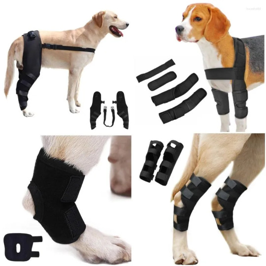
The veterinary orthotics-prosthetics market has seen significant growth in recent years due to an increasing demand for advanced solutions to enhance the mobility and quality of life for animals. Veterinary orthotics and prosthetics (O&P) refer to devices designed to assist animals suffering from mobility issues caused by injury, disease, or congenital conditions. These devices are typically custom-made to suit the unique anatomical structure of each animal, offering both functional and therapeutic benefits. With the rising awareness about animal healthcare and a greater emphasis on improving animal welfare, several key drivers have emerged, fueling the expansion of this market.
Growing Awareness of Animal Healthcare
One of the most significant drivers of the veterinary orthotics-prosthetics market is the increasing awareness surrounding animal healthcare. As more pet owners recognize the importance of medical treatments and rehabilitation for their animals, the demand for customized orthotic and prosthetic devices has risen. Pets, especially dogs and cats, often experience joint disorders, fractures, or amputations, necessitating rehabilitation through these devices. As people become more conscious of their pets' well-being, they are seeking solutions to manage pain, improve mobility, and ultimately enhance their quality of life.
Advancements in Veterinary Medicine and Technology
Technological advancements in veterinary medicine play a vital role in driving the veterinary orthotics-prosthetics market. The continuous development of 3D printing, CAD (computer-aided design) software, and materials science has led to more precise, effective, and affordable orthotic and prosthetic devices. These innovations have allowed for better customization of devices, ensuring a perfect fit for animals while improving comfort and mobility. In addition, the use of high-tech materials that mimic the natural movement of joints and bones has contributed to more durable and efficient solutions for pets.
Increase in Pet Ownership and Humanization of Pets
The humanization of pets has played a crucial role in the growth of the veterinary orthotics-prosthetics market. As pets are increasingly seen as members of the family, pet owners are willing to invest in treatments that enhance their pets' health and overall well-being. The rising number of pet adoptions, particularly in urban areas, has created a growing market for specialized healthcare solutions. With an increasing focus on providing pets with the same quality of care as humans, the demand for advanced orthopedic treatments and mobility devices has surged.
Rising Incidence of Pet Injuries and Disabilities
The rising incidence of injuries, diseases, and disabilities in pets has further contributed to the growth of the veterinary orthotics-prosthetics market. Accidents, joint issues, and congenital abnormalities have become more prevalent in both domestic and wild animals, necessitating the use of specialized orthotics and prosthetics. Dogs, for example, are particularly prone to hip dysplasia, fractures, and ligament tears, leading to the increasing demand for joint braces, prosthetic limbs, and other mobility aids. The aging population of pets also requires more frequent interventions to manage conditions like arthritis, driving the need for orthopedic solutions.
Support from Veterinary Professionals and Research
Veterinary professionals and research institutions play a crucial role in the development and adoption of orthotic and prosthetic devices. As more veterinary professionals embrace these technologies, they are not only improving treatment outcomes but also educating pet owners about the benefits of orthotic and prosthetic solutions. Additionally, ongoing research and clinical trials continue to optimize the design and functionality of these devices. With a growing body of evidence supporting the effectiveness of O&P treatments in animals, the market is expected to continue expanding.
Expanding Veterinary Care Networks and Facilities
The expansion of veterinary care networks and specialized animal hospitals has also contributed to the growth of the veterinary orthotics-prosthetics market. Veterinary clinics that offer specialized services, including orthotics and prosthetics, are becoming more common. This expansion has made these treatments more accessible to pet owners, leading to an increase in demand for customized solutions. As these services become more mainstream, pet owners are more likely to explore O&P devices as viable options for their animals' care.
In conclusion, the veterinary orthotics-prosthetics market is driven by a combination of factors, including increasing awareness of animal healthcare, technological advancements, the humanization of pets, rising pet injuries, and support from veterinary professionals. These drivers are shaping the future of veterinary care and rehabilitation, ultimately improving the lives of countless animals around the world.
3 notes
·
View notes
Text
How to Choose the Best ERP for Engineering and Manufacturing Industry
In today’s fast-paced world, engineering and manufacturing companies face increasing pressure to deliver high-quality products while maintaining efficiency and cost-effectiveness. Implementing the right Enterprise Resource Planning (ERP) software can significantly enhance operations, streamline workflows, and boost productivity. However, with numerous options available, selecting the best ERP software for the engineering and manufacturing industry can be challenging. This guide will help you navigate this decision-making process and choose the most suitable solution for your business.

Why ERP is Crucial for Engineering and Manufacturing
ERP software integrates various business processes, including production, inventory management, supply chain, finance, and human resources. For engineering and manufacturing companies, ERP solutions are particularly vital because they:
Facilitate real-time data sharing across departments.
Enhance supply chain management.
Optimize production planning and scheduling.
Ensure compliance with industry standards.
Reduce operational costs.
Partnering with the right Engineering ERP software company ensures that your organization leverages these benefits to stay competitive in a dynamic market.
Steps to Choose the Best ERP for Engineering and Manufacturing
1. Understand Your Business Needs
Before exploring ERP solutions, evaluate your company’s specific requirements. Identify the pain points in your current processes and prioritize the features you need in an ERP system. Common features for engineering and manufacturing companies include:
Bill of Materials (BOM) management
Production planning and scheduling
Inventory control
Quality management
Financial reporting
Consulting with a reputed ERP software company can help you match your needs with the right features.
2. Look for Industry-Specific Solutions
Generic ERP software might not address the unique needs of the engineering and manufacturing sector. Opt for an ERP software in India that offers modules tailored to your industry. Such solutions are designed to handle specific challenges like multi-level BOM, project costing, and shop floor management.
3. Check Vendor Expertise
Choosing a reliable vendor is as important as selecting the software itself. Research ERP solution providers with a strong track record in serving engineering and manufacturing companies. Look for reviews, case studies, and client testimonials to gauge their expertise.
4. Evaluate Scalability and Flexibility
Your business will grow, and so will your operational requirements. Ensure that the ERP system you choose is scalable and flexible enough to accommodate future needs. The top 10 ERP software providers in India offer scalable solutions that can adapt to changing business demands.
5. Assess Integration Capabilities
An ERP system must integrate seamlessly with your existing tools, such as Computer-Aided Design (CAD) software, Customer Relationship Management (CRM) systems, and IoT devices. A well-integrated system reduces redundancies and enhances efficiency.
6. Prioritize User-Friendliness
A complex system with a steep learning curve can hinder adoption. Choose an ERP software with an intuitive interface and easy navigation. This ensures that your employees can use the system effectively without extensive training.
7. Consider Customization Options
No two businesses are alike. While standard ERP solutions offer core functionalities, some companies require customization to align with specific workflows. A trusted ERP software company in India can provide custom modules tailored to your unique needs.
8. Focus on Data Security
Engineering and manufacturing companies often deal with sensitive data. Ensure that the ERP solution complies with the latest security standards and offers robust data protection features.
9. Compare Pricing and ROI
While cost is an important factor, it should not be the sole criterion. Evaluate the long-term return on investment (ROI) offered by different ERP software. A slightly expensive but feature-rich solution from the best ERP software provider in India may deliver better value than a cheaper alternative with limited functionalities.
10. Test Before You Commit
Most ERP software companies offer free trials or demo versions. Use these opportunities to test the software in a real-world scenario. Gather feedback from your team and ensure the solution meets your expectations before finalizing your decision.
Benefits of Partnering with the Best ERP Software Providers in India
India is home to some of the leading ERP software providers in India, offering state-of-the-art solutions for the engineering and manufacturing sector. Partnering with a reputable provider ensures:
Access to advanced features tailored to your industry.
Reliable customer support.
Comprehensive training and implementation services.
Regular updates and enhancements to the software.
Companies like Shantitechnology (STERP) specialize in delivering cutting-edge ERP solutions that cater specifically to engineering and manufacturing businesses. With years of expertise, they rank among the top 10 ERP software providers in India, ensuring seamless integration and exceptional performance.
Conclusion
Selecting the right ERP software is a critical decision that can impact your company’s efficiency, productivity, and profitability. By understanding your requirements, researching vendors, and prioritizing features like scalability, integration, and security, you can find the perfect ERP solution for your engineering or manufacturing business.
If you are looking for a trusted ERP software company in India, consider partnering with a provider like STERP. As one of the best ERP software providers in India, STERP offers comprehensive solutions tailored to the unique needs of engineering and manufacturing companies. With their expertise, you can streamline your operations, improve decision-making, and stay ahead in a competitive market.
Get in touch with STERP – the leading Engineering ERP software company – to transform your business with a reliable and efficient ERP system. Take the first step toward a smarter, more connected future today!
#Manufacturing ERP software company#ERP solution provider#Engineering ERP software company#ERP software company#ERP software companies
6 notes
·
View notes
Text
Mastering Woodworking with a CNC Router Machine: Unlocking Precision and Efficiency
The CNC router machine for wood has emerged as an indispensable tool for modern woodworking. Whether crafting intricate designs or scaling up production, this advanced technology brings precision, speed, and creativity to the forefront. Among its many variations, the 5x10 CNC router stands out for its large working area and robust functionality. This article delves into the transformative impact of CNC router machines on woodworking and why they are a must-have in today’s workshops.
What is a CNC Router Machine for Wood?
A CNC (Computer Numerical Control) router machine for wood is a sophisticated device that automates cutting, engraving, and carving processes. By using computer-aided designs (CAD), it translates digital plans into precise physical creations. This machine eliminates the challenges of manual craftsmanship, ensuring flawless results even for the most complex patterns.
Key Benefits:
Unmatched Accuracy: Create intricate details with pinpoint precision.
Time-Saving: Reduce production times significantly without compromising quality.
Versatility: Handle diverse projects, from furniture making to decorative carvings.
Consistency: Deliver identical results across multiple pieces, perfect for bulk production.
Exploring the 5x10 CNC Router
The 5x10 CNC router is a preferred choice for professionals who handle large-scale projects or work with oversized wooden sheets. Its generous 5-foot by 10-foot workspace allows for seamless execution of expansive designs, such as furniture panels, doors, and signage.
Features of the 5x10 CNC Router:
Ample Work Area: Ideal for cutting and engraving large materials without the need for piecing.
Precision Mechanics: Designed to maintain accuracy over extended working hours.
Tool Flexibility: Compatible with various attachments for added functionality, such as automated tool changers or multiple spindles.
This model is particularly useful in industries where size and detail matter, such as interior design and furniture manufacturing.
Applications of CNC Router Machines in Woodworking
CNC router machines have diverse applications across various woodworking domains, including:
Furniture Production: Create tables, chairs, cabinets, and other custom pieces with intricate designs.
Interior Décor: Produce unique wooden wall panels, decorative moldings, and ceiling details.
Architectural Designs: Craft custom doors, frames, and staircases with precision.
Artisanal Creations: Design engraved artwork, personalized gifts, and one-of-a-kind decorative items.
Sign Making: Build durable and aesthetically pleasing wooden signs with precision engravings.
Why Choose a CNC Router Machine for Wood?
Ease of Use: With user-friendly software and automated processes, CNC routers make complex projects manageable.
Material Optimization: Reduce waste with precise cutting and carving.
Scalable Production: Adaptable for one-off creations or large-scale manufacturing.
Cost Efficiency: While an initial investment is required, long-term savings are achieved through reduced material waste and increased productivity.
Conclusion
The CNC router machine for wood is a technological marvel that combines precision, versatility, and efficiency to revolutionize woodworking. Its ability to automate complex tasks while maintaining artistic integrity makes it an invaluable asset for both seasoned professionals and hobbyists. The 5x10 CNC router, with its expansive workspace, is especially suited for tackling large and detailed projects. Whether you aim to craft fine furniture or intricate designs, investing in a CNC router ensures that your woodworking ventures achieve excellence with every cut and carve.
2 notes
·
View notes
Text
Jewellery Designing Course in Delhi by NIDG Worldwide: Your Path to a Creative Career
Jewellery designing is not just an art; it is a way of expressing creativity, elegance, and culture through beautiful pieces of ornamentation. The Jewellery Designing Course in Delhi offered by NIDG Worldwide is one such platform that helps aspiring designers turn their passion into a profession. This comprehensive course is tailored to teach the nuances of designing, creating, and understanding the intricacies of jewellery in the best possible way.

What Makes Jewellery Designing a Great Career?
The jewellery industry in India is growing rapidly. With an increasing demand for exclusive and unique jewellery pieces, the need for skilled designers has also surged. A Jewellery Designing Course in Delhi opens up a plethora of opportunities for individuals who have an eye for detail and a passion for design. Whether you aspire to be a professional designer or wish to start your own jewellery brand, a structured course helps you get a strong footing in the industry.
Why Choose NIDG Worldwide?
NIDG Worldwide is a well-known name in the field of jewellery designing and training. Their Jewellery Designing Course in Delhi stands out due to the institution’s commitment to providing practical, hands-on learning experiences. Let’s explore the reasons why NIDG Worldwide should be your preferred choice:
Expert Faculty: The institution boasts a team of experienced professionals and industry experts who are passionate about passing on their knowledge. They provide the right mix of theoretical learning and practical training, helping students grasp essential design concepts and techniques.
Comprehensive Curriculum: The course covers everything from basic sketching to advanced computer-aided design (CAD). Students learn about various aspects like gemstone settings, metal crafting, and even digital jewellery design. The structured approach ensures that students are well-versed in all facets of jewellery designing.
State-of-the-Art Facilities: NIDG Worldwide offers modern infrastructure and up-to-date tools and software. Students get hands-on experience with professional-grade equipment and software that are widely used in the industry.
Career Guidance and Placement Support: At NIDG Worldwide, the focus is not just on teaching but also on helping students find the right career path. They offer placement assistance and guide students in setting up their own ventures or finding opportunities in reputed design houses.
Course Highlights
The Jewellery Designing Course in Delhi by NIDG Worldwide is structured to cater to beginners as well as professionals looking to upgrade their skills. Here are some highlights of the course:
Introduction to Jewellery Design: Understanding the fundamentals of jewellery design, including design theory, principles, and history.
Sketching and Rendering: Learning to sketch jewellery designs by hand and rendering them with shading and highlighting techniques to give a realistic feel.
Gemology Basics: An introduction to gemstones, their properties, and how they are used in different types of jewellery. Students gain knowledge of identifying various stones and using them appropriately in their designs.
CAD for Jewellery Design: Mastering computer-aided design (CAD) software to create precise, professional jewellery designs. Students learn to transform their sketches into detailed digital designs, preparing them for real-world projects.
Manufacturing Techniques: Understanding the processes involved in turning designs into actual jewellery pieces, including casting, metal forming, and stone setting.
Market Trends and Client Interaction: Learning about the latest trends in the jewellery market and how to interact with clients to understand their preferences and requirements.
Benefits of Enrolling in a Jewellery Designing Course
A Jewellery Designing Course in Delhi can be a stepping stone for anyone aspiring to enter this glamorous industry. Here are some key benefits of enrolling in this course:
Skill Development: You will acquire specialized skills in jewellery sketching, designing, and crafting, which will give you an edge in the competitive industry.
Creative Expression: Jewellery designing is all about expressing creativity and originality. Through this course, you will learn how to bring your creative ideas to life.
Career Opportunities: From working with established jewellery brands to launching your own business, a professional course opens up numerous career avenues.
Networking: Being a part of a reputed institution like NIDG Worldwide allows you to connect with industry experts, designers, and fellow students. Networking can help you find mentors, collaborators, and job opportunities.
Who Can Join?
The Jewellery Designing Course in Delhi by NIDG Worldwide is ideal for anyone with a passion for jewellery and design. Whether you are a student, a working professional looking for a career change, or someone keen on starting your own jewellery line, this course is designed to meet your needs. No prior experience is required, and the course is structured to build your skills from scratch.
Conclusion
In conclusion, a Jewellery Designing Course in Delhi by NIDG Worldwide offers a well-rounded education in the art and business of jewellery. It empowers aspiring designers with the knowledge and skills required to succeed in the industry. The course not only covers traditional designing methods but also introduces modern techniques and technologies. With expert guidance, hands-on training, and a focus on practical learning, NIDG Worldwide prepares students to excel in this competitive field.
If you have a flair for creativity and a desire to create stunning jewellery pieces, enrolling in a Jewellery Designing Course in Delhi could be your gateway to a fulfilling career. Take the first step towards your dream career with NIDG Worldwide, and let your creativity shine!
2 notes
·
View notes
Text
IEEE Project Center in Tirunelveli
AB Technologies: The Leading IEEE Project Center in Tirunelveli
Engineering students across Tamil Nadu often seek out the best resources for their final year projects, and AB Technologies has become the top choice for students in Tirunelveli. Known for its exceptional quality, innovation, and focus on practical learning, AB Technologies is recognized as the leading IEEE project center in Tirunelveli. Specializing in IEEE-certified projects, the center has carved a niche for itself by providing students with the tools, mentorship, and technical support they need to excel.
The Importance of IEEE Projects
IEEE (Institute of Electrical and Electronics Engineers) projects hold significant value for engineering students. These projects are based on international standards, representing the latest technological advancements and innovations across various fields of engineering. An IEEE-certified project not only strengthens a student’s academic performance but also boosts their resume, providing a strong competitive advantage in the job market. With industries increasingly focusing on cutting-edge technology and innovation, completing an IEEE-certified project from a reputable center like AB Technologies opens up greater career opportunities for students.
Diverse Project Offerings
AB Technologies offers a comprehensive range of project options across several branches of engineering, ensuring that every student can find a project that aligns with their interests and academic requirements. Some of the most popular project domains offered include:
Electronics and Communication Engineering (ECE): AB Technologies provides a variety of IEEE-certified projects in areas like embedded systems, digital communication, IoT (Internet of Things), and VLSI design. Students have the opportunity to work with advanced technologies and tools, preparing them for real-world challenges.
Electrical and Electronics Engineering (EEE): From power systems and electrical machines to renewable energy solutions, AB Technologies offers projects that focus on sustainable and emerging technologies. These projects help students gain a deeper understanding of modern power systems and electrical circuits.
Computer Science and Information Technology: In a field where technological advancements are rapid, AB Technologies offers projects in trending areas like artificial intelligence (AI), machine learning, cybersecurity, web development, and data science. These projects are designed to provide students with hands-on experience in the technologies shaping the future of the industry.
Mechanical Engineering: Mechanical engineering students can explore projects involving robotics, automation, CAD/CAM, and industrial design, gaining practical exposure to cutting-edge mechanical systems and technologies.
Expert Guidance and Mentorship
What sets AB Technologies apart from other project centers is its dedication to providing personalized mentorship. Each student receives one-on-one guidance from experienced professionals and academic experts who ensure that the project is not only completed successfully but also understood in-depth by the student. This mentorship covers every phase of the project, from initial concept and design to development, testing, and final presentation.
Focus on Hands-On Learning
At AB Technologies, students aren’t just completing projects for the sake of academic requirements; they’re getting hands-on, practical experience. The center is equipped with state-of-the-art tools, software, and hardware, allowing students to work on real-world applications of their projects. This practical exposure is invaluable in helping students understand the complexities of modern engineering solutions and preparing them for the challenges they will face in their professional careers.
Building a Reputation of Trust and Excellence
Over the years, AB Technologies has earned a strong reputation for its quality and commitment to excellence. The center has become a trusted partner for engineering students and educational institutions in Tirunelveli, thanks to its consistent track record of delivering successful IEEE projects. Many students have benefited from the expert guidance and innovative project solutions provided by AB Technologies, allowing them to stand out in their academic and professional journeys.
Conclusion
For engineering students in Tirunelveli looking to undertake IEEE-certified projects, AB Technologies is the clear choice. With its wide range of project offerings, expert mentorship, and hands-on learning opportunities, the center ensures that students not only meet their academic goals but also acquire valuable skills that will set them apart in the job market. As the leading IEEE project center in Tirunelveli, AB Technologies continues to empower students to succeed in their engineering careers.
Best IEEE expert engineering project center, Nagercoil | Tirunelveli | Chennai (abtechnologies.in)
#IEEE Project Center in Tirunelveli
#IEEE#Project#Center#in#Tirunelveli
##IEEEProjectCenterinTirunelveli

2 notes
·
View notes
Text
Rotary CNC Router Machine
At GK Laser Enterprises, we pride ourselves on delivering cutting-edge solutions to meet the evolving needs of the manufacturing and fabrication industries. One such innovation that has gained popularity for its versatility and precision is the Rotary CNC Router Machine. As a leader in CNC technologies, we offer a range of advanced CNC machines, and today we dive deep into how a rotary CNC router machine can revolutionize your operations.
What is a Rotary CNC Router Machine? A Rotary CNC Router Machine is a computer-controlled cutting machine that uses rotary tools to carve, cut, or engrave materials in three dimensions. The term “rotary” refers to its ability to rotate the material around an axis while it works, providing access to all sides of the material. This capability enables intricate detailing, sculpting, and shaping of cylindrical or irregularly shaped materials.
Unlike traditional CNC routers that work on flat surfaces, rotary CNC routers can handle 3D shapes, making them ideal for creating complex, multi-faceted designs.
How Does a Rotary CNC Router Machine Work? The Rotary CNC Router works by rotating the material, typically using a rotary axis attachment, while the cutting tool precisely follows the programmed paths. Here’s a breakdown of the process:
Material Preparation: A workpiece, such as wood, metal, or plastic, is mounted on the rotary axis, which allows it to rotate. Programming: A computer-aided design (CAD) program creates a digital blueprint of the desired outcome. This is then converted into machine-readable code using computer-aided manufacturing (CAM) software. Cutting Process: The router uses its rotary axis to rotate the material while the cutting tool moves along the X, Y, and Z axes to carve, cut, or engrave the material into the desired shape. Finishing: Once the operation is complete, the workpiece is inspected and may require minimal finishing, thanks to the machine’s precision.
Key Features of a Rotary CNC Router Machine High Precision and Accuracy: Rotary CNC routers are known for their precision in handling complex designs, offering high accuracy even in detailed cuts and engravings. Versatility: Whether you’re working with wood, metal, plastic, or composites, the rotary CNC router can handle a wide range of materials. This versatility makes it invaluable for industries such as furniture design, sculpture, and sign-making. 3D Carving and Engraving: With the ability to rotate the material, rotary CNC routers are ideal for creating 3D objects like sculptures, chair legs, moldings, and even complex cylindrical designs. Automation and Efficiency: The CNC aspect automates the cutting process, ensuring uniformity in production and reducing the need for manual labor. This enhances efficiency and speeds up production time.
Why Choose a Rotary CNC Router Machine for Your Business? If your business requires precision, complexity, and scalability, a rotary CNC router is a wise investment. At GK Laser Enterprises, we emphasize the value it can bring to industries like:
Furniture Manufacturing: Intricate 3D carvings and details for chair legs, columns, and sculptures can be easily achieved using rotary CNC routers. Sign Making and Woodworking: From large signs to ornate wood designs, rotary CNC routers deliver exceptional precision that elevates your craftsmanship. Sculpture and Artwork Creation: Artists and designers benefit from the ability to craft complex shapes and details, providing unmatched creativity. Metal and Plastic Fabrication: Industrial manufacturers who work with metals and plastics can create custom parts, components, and molds with great precision.
Benefits of Using a Rotary CNC Router Machine Enhanced Productivity: With automated processes, your business can take on more projects with faster turnaround times, maximizing profitability. Cost Efficiency: Despite the upfront investment, the long-term savings on labor, material waste, and improved product quality make it a highly cost-effective solution. Precision and Consistency: The automation ensures that each piece you produce is identical in quality and detail, improving overall consistency. Flexibility: Whether you’re producing one-of-a-kind custom pieces or bulk products, the rotary CNC router offers the flexibility to handle both with ease. Lower Material Waste: Precision machining ensures that there is minimal waste, reducing the cost of raw materials and promoting sustainable practices.
Why Buy From GK Laser Enterprises? At GK Laser Enterprises, we provide high-quality rotary CNC router machines tailored to meet the unique needs of businesses across industries. With our deep industry expertise, we ensure that you get the most suitable machine for your applications, ensuring optimal performance and cost-efficiency.
We also offer:
Comprehensive Training and Support: Our team will provide full training on how to operate and maintain your CNC router machine. Maintenance Services: Regular servicing to keep your machine running smoothly, ensuring minimal downtime and maximum output. Custom Solutions: We understand that every business has different requirements, so we provide customized solutions that best fit your needs.
Conclusion The Rotary CNC Router Machine offers unparalleled precision and flexibility, making it an essential tool for businesses involved in woodworking, metalworking, and creative design. At GK Laser Enterprises, we’re committed to providing top-tier CNC solutions that enhance productivity and reduce costs. By investing in a rotary CNC router, your business can stay ahead of the competition while delivering superior quality products. Contact us today to learn more about our CNC machines and how they can benefit your operations!

2 notes
·
View notes
Text
CADOpt Technologies: Premium PTC Partner & Top Value-Added Reseller In India

In the fast-evolving landscape of digital design and engineering, having a reliable partner for computer-aided design (CAD) solutions is crucial. CADOpt Technologies has emerged as a beacon of excellence in this domain, establishing itself as a premium PTC partner and one of the top value-added resellers in India. This article delves into the myriad ways CADOpt Technologies stands out, offering insights into their services, solutions, and customer-centric approach.
Comprehensive Solutions Offered by CADOpt Technologies
CAD Software Solutions
One of the core offerings of CADOpt Technologies is their suite of CAD software solutions. These tools are designed to enhance productivity, improve design accuracy, and streamline the engineering process. Some of the key software solutions provided include:
Creo: A robust 3D CAD software that supports product design and development from concept to manufacturing.
Windchill: A product lifecycle management (PLM) solution that facilitates collaboration and data management across the product development lifecycle.
ThingWorx: An industrial Internet of Things (IoT) platform that enables smart, connected operations and products.
Training and Support Services
Understanding that software is only as good as the people using it, CADOpt Technologies places a strong emphasis on training and support. They offer comprehensive training programs tailored to different user levels, ensuring that clients can fully harness the power of their CAD tools. Additionally, their dedicated support team is always on hand to assist with any technical issues, providing timely and effective solutions.
Customization and Integration
Every business has unique needs, and CADOpt Technologies excels in offering customized solutions. They work closely with clients to understand their specific requirements and tailor their CAD tools accordingly. Moreover, their expertise in software integration ensures seamless incorporation of CAD solutions into existing workflows, enhancing overall efficiency.
Why CADOpt Technologies is a Top Value-Added Reseller
Industry Expertise
One of the key factors that set CADOpt Technologies apart is their deep industry expertise. They have a team of seasoned professionals with extensive experience in various sectors, including automotive, aerospace, consumer goods, and industrial equipment. This diverse expertise enables them to provide insights and solutions that are precisely aligned with industry-specific challenges and opportunities.
Customer-Centric Approach
At the heart of CADOpt Technologies' success is their unwavering commitment to customer satisfaction. They adopt a consultative approach, working closely with clients to understand their goals and challenges. This collaborative mindset ensures that the solutions provided are not only effective but also add significant value to the client's business.
Strong After-Sales Support
After-sales support is a critical aspect of any technology partnership, and CADOpt Technologies excels in this regard. Their dedicated support team provides ongoing assistance, ensuring that clients can maximize the benefits of their CAD solutions. From troubleshooting technical issues to providing regular updates and maintenance, CADOpt Technologies is committed to long-term client success.
The Future of CADOpt Technologies
Innovation and Growth
Looking ahead, CADOpt Technologies is poised for continued growth and innovation. They are constantly exploring new technologies and trends to stay ahead of the curve. Their ongoing investment in research and development ensures that they can offer cutting-edge solutions that meet the evolving needs of their clients.
Expansion Plans
CADOpt Technologies has ambitious plans for expansion, both geographically and in terms of service offerings. They aim to extend their footprint across India and beyond, bringing their world-class CAD solutions to a broader audience. Additionally, they are exploring new verticals and industries, leveraging their expertise to drive digital transformation in various sectors.
Conclusion
CADOpt Technologies stands out as a premium PTC partner and top value-added reseller in India, thanks to their innovative solutions, exceptional customer service, and deep industry expertise. Their comprehensive suite of CAD software, coupled with their commitment to customization, training, and support, makes them a trusted partner for businesses seeking to enhance their design and engineering capabilities. As they continue to grow and innovate, CADOpt Technologies is set to play a pivotal role in shaping the future of the CAD industry in India and beyond. For more information on CADOpt Technologies and their offerings, visit their official website or contact their support team for personalized assistance.
#CADOptTechnologies#PTCPartner#CADSolutions#ValueAddedReseller#IndiaTech#CreoSoftware#WindchillPLM#ThingWorxIoT#EngineeringExcellence#DigitalTransformation#TechInnovation#CustomerSupport#CADTraining#IndustryExpertise#ProductDesign#EngineeringSoftware#CADIntegration#TechGrowth#InnovationInCAD#FutureOfDesign#TechResellerIndia
2 notes
·
View notes
Text
Mastering AutoCAD: A Comprehensive Guide to Advanced Design Challenges

In the dynamic realm of design and drafting, the mastery of AutoCAD stands as a cornerstone skill for individuals aspiring to excel in fields such as engineering, architecture, and design. As students embark on their academic journey toward a Master's degree, they are met with a series of intricate challenges that extend beyond routine tasks, pushing the boundaries of their technical expertise. These challenges not only serve as assessments of their proficiency in AutoCAD but also require a strategic and innovative mindset to navigate complex problem-solving scenarios. This blog aims to delve into the intricacies of five master's degree level questions in AutoCAD, unraveling the layers of complexity inherent in the world of computer-aided design and providing valuable insights for those navigating this educational landscape.
The pursuit of excellence in AutoCAD at the master's degree level demands a holistic understanding of the software's capabilities, creative problem-solving skills, and a willingness to seek assistance when faced with intricate challenges. Help with AutoCAD assignments becomes not just a keyword but a beacon guiding students through the complexities of advanced design tasks, fostering a learning environment where theoretical knowledge meets practical application, ultimately preparing them for success in the ever-evolving field of computer-aided design.
1. Advanced 3D Modeling in AutoCAD
Problem: The challenge begins with designing a complex 3D model incorporating diverse geometric shapes. The solution not only involves creating intricate shapes but also optimizing the model for efficient rendering. This question delves into not just the technical aspects of modeling but also strategic considerations for a seamless design process.
2. Dynamic Blocks and Parametric Design
Problem: Dynamic blocks and parametric design are at the forefront of modern CAD practices. Creating a parametrically controlled dynamic block for a furniture component challenges students to think beyond static designs. The solution involves understanding the dynamic properties, establishing relationships between parameters, and discussing the advantages of dynamic blocks in real-world design workflows.
3. AutoCAD Customization with AutoLISP
Problem: AutoLISP programming is a powerful tool for customization in AutoCAD. Crafting a custom command or routine to streamline a specific design task showcases not only programming skills but also the practical application of customization in a professional setting. The solution includes providing the complete AutoLISP code, explaining its functionality, and discussing its impact on workflow efficiency.
4. Collaborative Design in AutoCAD
Problem: Collaborative design is a crucial aspect of many projects. This question challenges students to create a multi-user environment in AutoCAD, emphasizing features like "Xref," "Sheet Sets," or "CAD Standards" to streamline collaboration. The solution addresses challenges in coordinating design changes, managing references, and ensuring consistency across the project.
5. AutoCAD and BIM Integration
Problem: The integration of AutoCAD into a Building Information Modeling (BIM) workflow is a contemporary challenge. Students are tasked with showcasing the interoperability of AutoCAD with BIM tools and discussing the advantages of this integration. This question highlights the importance of understanding how AutoCAD fits into broader design and construction processes.
Help with AutoCAD Assignments: Navigating the Complexity
Undoubtedly, mastering AutoCAD requires a combination of theoretical knowledge and practical application. As students grapple with these challenging questions, seeking help with AutoCAD assignments becomes crucial. Understanding the nuances of each problem and refining one's skills often involves guidance from experts in the field.
Whether it's elucidating the intricacies of 3D modeling, unraveling the mysteries of AutoLISP programming, or addressing the challenges of collaborative design, a reliable source of assistance can make a significant difference. For those seeking help with AutoCAD assignments, various online platforms and professional tutors offer personalized guidance to ensure a deeper understanding of the subject matter.
In conclusion, tackling master's degree level AutoCAD questions goes beyond routine design tasks. It requires a holistic understanding of the software's capabilities, strategic thinking, and the ability to adapt to modern design practices. As students navigate these challenges, seeking assistance not only enhances their learning experience but also sets the foundation for a successful career in the dynamic world of computer-aided design.
#Autocad Assignment Help#Autocad Assignment Helper#Help with Autocad Assignments#Do My Autocad Assignment#Complete My Autocad Assignment
8 notes
·
View notes
Text
How CAD Technology Transforms Accuracy and Efficiency in Land Surveying

Land surveying is a critical process in the fields of construction, engineering, and land development. It involves measuring and mapping the terrestrial or three-dimensional space to determine boundaries, land features, and property lines. Traditionally, land surveying relied heavily on manual techniques and rudimentary tools, leading to time-consuming and often error-prone results. However, with the advent of Computer-Aided Design (CAD) technology, the landscape of land surveying has transformed dramatically. CAD has brought about significant improvements in accuracy and efficiency, revolutionizing the industry. In this blog post, we will delve into the various ways CAD enhances land surveying and explore its benefits in detail.
The Role of CAD in Land Surveying
CAD, or Computer-Aided Design, is a technology used for creating, modifying, analyzing, and optimizing designs. In the context of land surveying, CAD software helps surveyors create detailed and precise maps and plans of land areas. The integration of CAD in land surveying involves the use of specialized software that allows surveyors to input data, process measurements, and generate accurate digital representations of physical spaces.
Enhanced Accuracy
One of the most significant advantages of CAD in land surveying is the enhanced accuracy it provides. Traditional surveying methods often involved manual calculations and hand-drawn maps, which were susceptible to human error. In contrast, CAD software offers tools that automate many of these processes, reducing the likelihood of mistakes. Here are some ways CAD improves accuracy:
1. Precision in Measurements: CAD software can handle and process complex mathematical calculations with precision. Surveyors can input raw data collected from the field directly into the software, which then accurately converts these measurements into detailed maps and models. This eliminates errors associated with manual data entry and calculation.
2. Detailed and Scalable Maps: CAD allows for the creation of highly detailed and scalable maps. Surveyors can zoom in and out without losing accuracy, enabling them to examine specific areas closely and ensure every detail is accounted for. This level of detail is crucial for identifying potential issues and making informed decisions.
3. Real-Time Data Processing: Modern CAD software can process data in real time, providing surveyors with immediate feedback. This capability allows for quick adjustments and corrections in the field, ensuring that the final survey is as accurate as possible.
4. Integration with GPS and GIS: CAD software often integrates seamlessly with Global Positioning System (GPS) and Geographic Information System (GIS) technology. This integration allows surveyors to import precise location data directly into their CAD models, further enhancing accuracy and providing a comprehensive view of the surveyed area.
Increased Efficiency
Efficiency is another key area where CAD excels in land surveying. The traditional surveying process was labor-intensive and time-consuming, often requiring surveyors to spend days or even weeks in the field. CAD technology streamlines many aspects of this process, leading to significant time savings and increased productivity. Here’s how CAD boosts efficiency in land surveying:
1. Automated Data Processing: CAD software can automate many of the repetitive and time-consuming tasks involved in land surveying. For example, it can automatically generate contour lines, calculate areas and volumes, and create cross-sections. This automation reduces the workload on surveyors and speeds up the overall process.
2. Simplified Data Management: Managing large amounts of data can be challenging, especially in large-scale land surveying projects. CAD software offers robust data management tools that allow surveyors to organize, store, and retrieve data easily. This simplifies the workflow and ensures that all information is readily accessible when needed.
3. Collaborative Capabilities: CAD software often includes collaborative features that enable multiple team members to work on the same project simultaneously. This collaborative approach enhances communication and coordination, leading to faster completion times and fewer misunderstandings.
4. Efficient Fieldwork: With CAD, surveyors can use mobile devices and specialized equipment to collect data in the field more efficiently. This data can be uploaded to the CAD software on the go, reducing the need for repeated site visits and minimizing downtime.
Visualization and Analysis
Visualization and analysis are critical components of land surveying, and CAD technology excels in these areas as well. The ability to create detailed visual representations of surveyed areas and perform in-depth analyses is invaluable for surveyors, engineers, and developers. Here are some ways CAD enhances visualization and analysis:
1. 3D Modeling: CAD software enables surveyors to create three-dimensional models of land areas. These 3D models provide a realistic representation of the terrain, allowing for better analysis and planning. Stakeholders can visualize the land’s topography, identify potential challenges, and make informed decisions based on accurate data.
2. Overlaying Data: CAD allows for the overlaying of different types of data on a single map. For example, surveyors can combine topographical data with utility lines, property boundaries, and environmental features. This comprehensive view helps in identifying potential conflicts and planning accordingly.
3. Simulation and Scenario Planning: CAD software can simulate various scenarios and predict their outcomes. For instance, surveyors can model the impact of construction on a particular area, assess potential drainage issues, or analyze the effects of environmental changes. This capability aids in proactive planning and risk management.
4. Detailed Reports and Documentation: CAD software can generate detailed reports and documentation based on the surveyed data. These reports can include measurements, calculations, maps, and 3D models, providing a comprehensive overview of the surveyed area. Such documentation is essential for legal, regulatory, and planning purposes.
Cost Savings
The improvements in accuracy, efficiency, and visualization brought about by CAD also translate into significant cost savings. By reducing errors and streamlining processes, CAD helps surveyors and their clients save money in various ways:
1. Reduced Rework: Accurate surveys mean fewer mistakes and less rework. Errors in traditional surveys often led to costly revisions and delays. CAD minimizes these errors, ensuring that the project stays on schedule and within budget.
2. Optimized Resource Allocation: Efficient data processing and management allow surveyors to optimize the use of resources, including time, labor, and equipment. This optimization leads to cost savings and better project management.
3. Minimized Site Visits: With the ability to process and analyze data remotely, CAD reduces the need for multiple site visits. This not only saves time but also reduces travel and labor costs.
4. Improved Decision-Making: Accurate and detailed surveys provide valuable insights that aid in decision-making. This leads to better project planning, fewer unforeseen issues, and more efficient use of resources, all of which contribute to cost savings.
Future Prospects of CAD in Land Surveying
As technology continues to advance, the role of CAD in land surveying is expected to grow even more significant. Emerging technologies such as Building Information Modeling (BIM), drones, and LiDAR (Light Detection and Ranging) are being integrated with CAD software, further enhancing its capabilities. Here are some future prospects for CAD in land surveying:
1. Integration with Drones: Drones equipped with high-resolution cameras and LiDAR sensors can capture detailed aerial imagery and topographical data. This data can be imported into CAD software for precise mapping and analysis. The use of drones reduces the time and effort required for fieldwork and provides access to hard-to-reach areas.
2. Building Information Modeling (BIM): BIM is a digital representation of the physical and functional characteristics of a building. Integrating BIM with CAD allows for a seamless transition from land surveying to construction planning and management. This integration improves collaboration between surveyors, architects, and engineers, leading to more efficient project execution.
3. Augmented Reality (AR) and Virtual Reality (VR): AR and VR technologies can enhance the visualization capabilities of CAD software. Surveyors and stakeholders can use AR and VR to explore 3D models in an immersive environment, gaining a better understanding of the terrain and potential challenges. This immersive experience aids in decision-making and improves communication.
4. Artificial Intelligence (AI) and Machine Learning: AI and machine learning algorithms can analyze large datasets quickly and accurately. When integrated with CAD, these technologies can automate complex analyses, identify patterns, and predict potential issues. This capability enhances the efficiency and accuracy of land surveying.
Conclusion
CAD has revolutionized the field of land surveying by improving accuracy, efficiency, and visualization capabilities. The precision and automation offered by CAD software reduce errors and streamline processes, leading to significant time and cost savings. As technology continues to evolve, the integration of CAD with emerging technologies such as drones, BIM, AR, VR, and AI will further enhance its capabilities, making land surveying even more efficient and accurate. For surveyors, engineers, and developers, embracing CAD technology is not just an option but a necessity for staying competitive and delivering high-quality results in today's fast-paced and demanding environment.
#Land Surveying#outsource cad drafting services#Surveying#Land Survey#Land Surveying Software#Land Survey Drafting Services#Land Survey CAD Drafting Services#Alta Survey#Subdivision Plats#Title Survey#Pipeline Surveys#Construction Survey#Site Planning Survey#Boundary and Location Survey#Topographic Survey#Residential Mortgage Survey#Tower Survey#Radius Map#Utility survey
2 notes
·
View notes
Text
Summary Analysis of CNC Milling Process

In modern manufacturing, CNC milling technology is widely used for its high precision and flexibility. Whether it's a mechanical part, an automotive component, or a component for a medical device, CNC milling provides excellent machining results.
What is CNC Milling?
CNC milling is a computer-controlled machining process that utilises a rotating tool to cut a workpiece. CNC milling allows for greater accuracy and consistency than traditional manual milling. It is often combined with other machining methods (e.g. turning, drilling) to meet different and diverse manufacturing needs.
Workflow of CNC Milling
Design stage In the initial stages of CNC milling, designers use Computer-Aided Design (CAD) software to create a model of the product. Commonly used software includes SolidWorks and Autodesk, which are tools that help designers accurately draw the shape and dimensions of the desired part.
Programming stage Once the design is complete, the CAD file needs to be converted to G-code, a language that CNC machines can understand. With Computer-Aided Manufacturing (CAM) software, the design files are converted into machine-executable instructions that enable automated machining.
Machine setting During the machine set-up phase, the workpiece needs to be fixed to the table and a suitable tool selected. At the same time, the operator needs to set the initial co-ordinates to ensure accurate positioning during machining.
Advantages of CNC Milling
High precision and dimensional stability CNC milling allows for micron-level machining accuracy, ensuring consistency from part to part.
Complex shapes can be processed Whether it's a simple flat surface or a complex three-dimensional structure, CNC milling can handle it with ease.
Efficient production capacity Due to its high degree of automation, CNC milling can significantly increase productivity and shorten lead times.
Applications of CNC Milling
CNC milling technology is used in a wide range of industries, including:
Mechanical parts: Used in the manufacture of key components in a variety of mechanical equipment.
Automotive parts: High-precision parts for the automotive industry, such as engine components.
Medical device parts: Ensure the reliability and safety of medical devices.
Optical product parts: For the production of optical instruments and related products.
Frequently Asked Questions
What materials can be CNC milling machined? CNC milling is suitable for a wide range of materials, including metals (e.g. aluminium, steel), plastics, wood, and more. However, for some materials, such as ceramics or certain composites, the machining is more difficult and requires special handling.
What are the limitations of CNC milling? Despite its advanced technology, CNC milling has some limitations. For example, machining may be limited for internal vertical angles or very complex small structures.In addition, high hardness materials may lead to faster tool wear, which can affect productivity.
Comparison of CNC milling with other manufacturing technologies The advantages and disadvantages of each can be seen when comparing CNC milling with other manufacturing techniques such as 3D printing. CNC milling is generally superior to 3D printing in terms of accuracy and surface finish, but 3D printing has advantages in rapid prototyping and complex geometries. In terms of cost-effectiveness, the choice of technology depends on specific project needs and budget.
Summary
In summary, CNC milling is an indispensable manufacturing technology that plays an important role in several industries with its efficiency, precision and flexibility.
#prototyping#prototype#rapid prototyping#prototype machining#precision machining#cnc machining#cnc milling#machining parts#cnc milling 5 axis#cnc milling machining#cnc milling turning#precision cnc milling#cnc milling parts
2 notes
·
View notes
Text
Understanding the Importance of HVAC Drawings and Blueprints: A Comprehensive Guide

Table of Contents: 1.Importance of HVAC Drawings 2.Purpose of HVAC Blueprints 3.Understanding HVAC Systems 4.Types of HVAC Drawings 5.Reading HVAC Drawings & Blueprints 6.Creating HVAC Drawings 7.Tips for Efficient HVAC Drawing Creation 8.Reading & Analyzing HVAC Blueprints 9.Importance of Blueprints in HVAC Installation 10.How HVAC Drawings Improve Maintenance and Troubleshooting 11.Future Trends in HVAC Drawing and Blueprint Technology 12.Conclusion
Importance of HVAC Drawings
HVAC (Heating, Ventilation, and Air Conditioning) drawings are fundamental blueprints essential for the design, installation, and maintenance of HVAC systems in buildings. These drawings provide a visual representation of the HVAC system's layout, including ductwork, piping, equipment placement, and electrical connections. They serve as a crucial communication tool between architects, engineers, contractors, and technicians, ensuring that the HVAC system functions effectively and efficiently.
Purpose of HVAC Blueprints HVAC blueprints serve multiple purposes throughout the lifecycle of a building. During the design phase, they help architects and engineers conceptualize the HVAC system's layout, ensuring optimal space utilization and compliance with building codes and regulations. During construction, blueprints guide contractors and technicians in the accurate installation of HVAC components, minimizing errors and rework. Additionally, these blueprints serve as reference documents for maintenance and troubleshooting tasks throughout the building's lifespan.
Understanding HVAC Systems Before delving into the specifics of HVAC drawings and blueprints, it's essential to understand the components and principles of HVAC systems. HVAC systems are designed to control indoor temperature, humidity, and air quality to create a comfortable and healthy indoor environment. They typically comprise heating units (such as furnaces or boilers), ventilation systems (including ductwork and fans), air conditioning units, and controls for regulation.
Types of HVAC Drawings HVAC drawings come in various types, each serving a specific purpose:
Floor Plans: Provide a bird's-eye view of the building layout, indicating the placement of HVAC equipment, vents, and ductwork.
Elevation Drawings: Offer vertical views of HVAC components, illustrating their height and position relative to other building features.
Sectional Drawings: Show cross-sectional views of HVAC systems, revealing internal details like ductwork and piping arrangements.
Schematics: Present simplified diagrams of HVAC systems, highlighting connections and flow paths for air and fluids.
Isometric Drawings: Provide 3D representations of HVAC components, offering a clearer understanding of spatial relationships and installation requirements.
Reading HVAC Drawings & Blueprints: Proficiently interpreting HVAC drawings and blueprints is essential for architects, engineers, contractors, and technicians. It requires a thorough understanding of symbols, annotations, scales, and industry standards. Symbols represent various HVAC components, such as fans, dampers, valves, and thermostats, while annotations provide critical information like dimensions, materials, and performance specifications. Additionally, familiarity with scales ensures accurate measurement and placement of components within the building layout.
Creating HVAC Drawings
Creating HVAC drawings involves a collaborative effort among architects, engineers, and designers. Modern CAD (Computer-Aided Design) software facilitates the drafting process, allowing for precise modeling and documentation of HVAC systems. Designers input architectural plans and specifications into CAD software, where they can manipulate components, generate layouts, and produce detailed drawings with ease. CAD software also enables revisions and updates to accommodate changes in project requirements or building codes.
Tips for Efficient HVAC Drawing Creation: To streamline the HVAC drawing creation process, consider the following tips:
Standardization: Establish standardized symbols, templates, and procedures to ensure consistency across drawings.
Clarity: Use clear and concise labeling, annotations, and legends to enhance readability and comprehension.
Accuracy: Double-check measurements, calculations, and specifications to minimize errors and discrepancies.
Collaboration: Foster open communication and collaboration among design team members to address potential conflicts or challenges early in the process.
Documentation: Maintain detailed records of revisions, approvals, and design decisions to track the evolution of HVAC drawings throughout the project lifecycle.
Reading & Analyzing HVAC Blueprints When reading HVAC blueprints, it's essential to pay attention to key elements such as:
Equipment Placement: Identify the location of HVAC units, vents, registers, and exhaust fans to ensure optimal airflow and distribution.
Ductwork Layout: Analyze the routing and sizing of ductwork to minimize pressure drops and airflow restrictions.
Piping Configuration: Review the layout of piping systems for heating, cooling, and fluid distribution, ensuring proper insulation and support.
Electrical Connections: Verify the placement and wiring of electrical components, such as motors, controllers, and sensors, to ensure safe and efficient operation.
Importance of Blueprints in HVAC Installation Accurate HVAC blueprints are critical for the successful installation of HVAC systems, as they provide precise instructions for contractors and technicians. By following the blueprints closely, installers can ensure that components are positioned correctly, connections are made accurately, and systems are commissioned properly. This adherence to the blueprint minimizes installation errors, reduces rework, and improves overall project efficiency and quality.
How HVAC Drawings Improve Maintenance and Troubleshooting Throughout the lifecycle of a building, HVAC drawings play a vital role in maintenance and troubleshooting activities. Maintenance technicians rely on blueprints to locate equipment, access service points, and perform routine inspections and repairs efficiently. When troubleshooting HVAC issues, technicians can refer to drawings to identify potential sources of problems, such as duct leaks, valve malfunctions, or electrical faults, enabling quicker diagnosis and resolution.
Future Trends in HVAC Drawing and Blueprint Technology The future of HVAC drawing and blueprint technology is marked by advancements in digitalization, automation, and integration. CAD software continues to evolve with features like 3D modeling, virtual reality (VR) simulation, and cloud collaboration, enhancing design visualization and communication. Building Information Modeling (BIM) platforms integrate HVAC drawings with other building systems, fostering greater coordination and efficiency throughout the construction process. Additionally, IoT (Internet of Things) sensors and AI (Artificial Intelligence) algorithms offer predictive maintenance capabilities, enabling proactive system monitoring and optimization.
Conclusion In conclusion, HVAC drawings and blueprints are indispensable tools for the design, installation, and maintenance of HVAC systems in buildings. By providing detailed visual representations of system layouts, components, and connections, these drawings facilitate effective communication and collaboration among project stakeholders. Whether creating drawings from scratch or interpreting existing blueprints, architects, engineers, contractors, and technicians must possess the necessary skills and knowledge to ensure the successful implementation and operation of HVAC systems. As technology continues to advance, embracing digital tools and techniques will further enhance the efficiency, accuracy, and sustainability of HVAC drawing and blueprint processes.
#gsourcetechnologies#architecturedesigns#engineeringdesigns#cad services#hvacdrawings#caddrafting#hvacservices#hvacsolutions#draftingservices
2 notes
·
View notes
Text
What are the main challenge does Steel industry is facing now? What are the top five key challenges and potential solutions in Steel industry?
The Tool and Die Steel industry faces several common issues that can impact productivity, quality, and overall efficiency. The top five key challenges and potential solutions:
Tool Wear and Failure: 😒Tools and Dies can experience wear and failure over time, affecting the quality of the produced parts. 👉Solution: Implement a regular maintenance schedule to inspect and replace worn-out parts. Use high-quality tool steels and coatings to enhance durability.
Material Selection: 😒 Choosing the right tool and die materials for specific applications can be challenging. 👉Solution: Conduct thorough material analysis and consider factors like hardness, toughness, and wear resistance. Collaborate with material experts to make informed decisions.
Heat Treatment Issues: 😒Inconsistent heat treatment can lead to variations in hardness and other material properties. 👉 Solution: Develop and adhere to precise heat treatment processes. Monitor and control temperature, quenching, and tempering to ensure consistent results.
Precision and Tolerance Challenges: 😒Achieving tight tolerances and precision in manufacturing can be difficult. 👉Solution: Invest in high-precision machining equipment and regularly calibrate machines. Implement quality control measures such as statistical process control (SPC) to monitor and improve tolerances.
Tool Design Complexity: 😒Complex tool and die designs can lead to increased production time and costs. 👉Solution: Utilize computer-aided design (CAD) software to streamline the design process. Optimize designs for manufacturability to reduce complexity and improve efficiency.
Addressing these common issues requires a holistic approach that combines technological innovation, skilled workforce development, and robust quality control measures.
Virat Special Steels can assess the quality, mechanical properties, structural integrity, and dimensional accuracy of their die blocks. This helps them deliver reliable and high-quality products to their customers, meeting their expectations and ensuring successful forming processes.
Contact Us Today: Ready to elevate your projects with top-quality die steel? Contact VIRAT SPECIAL STEELS PVT. LIMITED , INDIA today!
Learn More: https://www.viratsteels.com/
Any further queries feel free to contact us : Email: [email protected] or Call: +91 98140 21775
#ludhiana#india#viratsteels#gurgaon#viratspecialsteels#toolsteelsupplier#pune#gurugram#iso9001#steel#HotWorkSteel#ToolSteel#db6steel#SteelAlloys#IndustrialMaterials#ManufacturingExcellence#MachiningSteel#SteelSupplier#H13ToolSteel
2 notes
·
View notes
Text
Mechanical Drawings - Digital Suntech
Mechanical drawing, also known as technical drawing or engineering drawing, is a form of communication used by engineers, architects, and other professionals to convey the details of a design. It is a precise and standardized way of representing objects and their relationships in a two-dimensional or three-dimensional space. Here are some key aspects of mechanical drawing:
Orthographic Projection:
Mechanical drawings typically use orthographic projection, where a three-dimensional object is represented by two-dimensional views from different angles. Common views include front, top, side, and isometric views.
Line Types:
Different line types are used to represent various features. For example, solid lines may represent visible edges, while dashed lines may represent hidden or invisible edges.
Dimensioning:
Dimensions are essential in mechanical drawings to provide accurate information about the size and location of features. Dimensions are typically expressed in terms of length, width, and height.
Scale:
Drawings are often created to scale, meaning that the size of the drawing reflects a proportional reduction or enlargement of the actual object. Common scales include 1:1, 1:2, 1:5, etc.
Symbols and Notations:
Symbols and notations are used to represent specific features or materials. Examples include welding symbols, surface finish symbols, and material specifications.
Title Block:
A title block is usually included in the drawing, providing information such as the title, drawing number, date, scale, and the name of the drafter or designer.
Isometric Drawings:
In addition to orthographic projections, isometric drawings may be used to represent three-dimensional objects in a more realistic way.
CAD (Computer-Aided Design):
Many mechanical drawings are now created using computer-aided design (CAD) software, which allows for more precise and efficient drafting.
Tolerances:
Tolerance information is often included to specify the acceptable variations in dimensions.
Revision History:
Drawings may include a revision history to track changes and updates made to the design over time. Creating accurate and detailed mechanical drawings is crucial for manufacturing, construction, and other industries where precise specifications are essential for the fabrication of products or structures.
Digital Suntech is a specialized firm proficient in the creation of meticulous mechanical drawings and a wide array of illustrations. Leveraging cutting-edge digital technologies and expertise in computer-aided design (CAD), Digital Suntech excels in producing detailed and precise engineering drawings that cater to diverse industries. Their skillful team employs orthographic projection, dimensioning, and sophisticated line types to accurately convey the intricacies of designs, ensuring seamless communication between engineers, architects, and manufacturers. With a commitment to quality and efficiency, Digital Suntech stands as a reliable partner for clients seeking top-notch illustrations, whether for manufacturing processes, construction projects, or other applications requiring precision and clarity in technical documentation.
Contact Digital Suntech for expertly crafted patent mechanical drawings and a comprehensive range of illustrations. Our skilled team utilizes cutting-edge technology to deliver precise and detailed designs, ensuring your intellectual property is accurately represented and protected. Trust Digital Suntech for all your illustration needs, from patent applications to technical documentation.

#mechanical drawing#patent illustration#patent drawings#digital suntech#technical drawing#isometric drawings#intellectual property#mechanical patent drawings
3 notes
·
View notes