#arduino camera image recognition
Explore tagged Tumblr posts
Visit Tumblr Blog
Explore Tumblr blogs with no restrictions, modern design and the best experience.
Last Seen Tumblr Blogs


Fun Fact
1,644 Tumblr posts in 1 second.
Text
Top Skills You’ll Learn in a Robotics and Artificial Intelligence Course
In a world that’s rapidly embracing automation, machine intelligence, and smart systems, careers in robotics and artificial intelligence (AI) are more promising than ever. From healthcare robots to self-driving cars and intelligent customer support systems, AI and robotics are becoming integral to modern life.
If you're considering robotics and artificial intelligence courses, you're not just choosing a degree — you're preparing to be part of a technological revolution. But what exactly will you learn in such a program? Let’s explore the most important skills these courses help you develop, and how they prepare you for the future of innovation.
Programming Fundamentals for AI and Robotics
Whether a robot arm on a manufacturing floor or a chatbot handling customer queries, everything begins with programming. Students learn core languages such as:
Python: Widely used in AI and machine learning applications.
C/C++: Essential for embedded systems and robotic control.
Java: Useful in software development and some machine learning frameworks.
Understanding data structures, control flow, and algorithms is foundational for writing efficient code for intelligent systems.
Machine Learning and Deep Learning Techniques
At the heart of AI lies machine learning — the ability for machines to learn from data. Students gain practical knowledge of:
Supervised and unsupervised learning
Neural networks and deep learning frameworks like TensorFlow and PyTorch
Natural Language Processing (NLP) for text and voice-based AI systems
These skills are critical for creating models that can analyze data, make predictions, and improve over time.
Robotics System Design and Control
In robotics, it’s all about building machines that sense, think, and act. You'll learn how to:
Design mechanical structures and integrate them with electronics
Work with sensors (like LIDAR, cameras, gyros) and actuators
Apply control systems theory to ensure precise movements and decisions
These concepts are essential in developing autonomous systems, from robotic arms to drones.
Embedded Systems and IoT Integration
Modern robots and smart devices often rely on embedded systems — mini-computers that perform dedicated functions. You'll learn to:
Program microcontrollers (like Arduino or Raspberry Pi)
Work with real-time operating systems
Connect devices using IoT protocols (like MQTT)
This hands-on knowledge is critical for building responsive and connected devices.
Computer Vision and Image Processing
Robots and AI systems need eyes — and that’s where computer vision comes in. This skill allows machines to:
Interpret visual data from cameras or sensors
Recognize objects, track movements, and detect patterns
Use tools like OpenCV to process and analyze images
Applications range from facial recognition to robotic navigation.
AI Ethics and Responsible Innovation
With great power comes great responsibility. As AI systems become more influential, engineers must understand:
Ethical implications of automation and decision-making
Bias in AI models
Data privacy and security concerns
Courses now include modules that prepare students to design responsible and inclusive technologies.
Soft Skills for Cross-Disciplinary Collaboration
It’s not all about tech. Robotics and AI projects often involve teamwork across domains. You’ll develop:
Communication and presentation skills
Project management techniques
Creative thinking and problem-solving abilities
These soft skills ensure that your innovative ideas are clearly conveyed and efficiently executed in real-world scenarios.
Real-World Projects and Internships
A good robotics and AI course doesn't end with classroom theory. Students gain experience through:
Capstone projects where they design, build, and deploy AI or robotic systems
Industry internships that provide exposure to real-world applications
Hackathons and competitions that encourage innovation under pressure
This kind of hands-on experience is crucial in standing out during placements and job interviews.
Choosing the Right Institution Matters
The quality of your learning experience depends heavily on where you study. The best robotics and artificial intelligence courses provide a mix of strong academic foundation, practical labs, and industry exposure.
At NITTE University, particularly through its NMAM Institute of Technology (NMAMIT), students receive a future-focused education that combines cutting-edge theory with real-world skills. With dedicated labs, advanced AI and robotics curriculum, and partnerships with industry leaders, NMAMIT prepares students not just for today’s tech world—but for the challenges of tomorrow.
1 note
·
View note
Video
youtube
Smart QR-Code Based Door Lock System Using ESP32-CAM \Wi -Fi Door Lock System Using ESP32 CAM Based on IoT | IoT Operated Door Lock using ESP32 CAM Module | ESP32-CAM Face Recognition Door Lock System | IoT based Door Access Control System using ESP32cam | esp32-cam face recognition door lock system | face recognition door lock system using esp32-cam ppt | WiFi door locking System using ESP32 project report | esp32-cam face detection door lock system ieee paper***********************************************************If You Want To Purchase the Full Working Project KITMail Us: [email protected] Name Along With You-Tube Video LinkWe are Located at Telangana, Hyderabad, Boduppal. Project Changes also Made according to Student Requirementshttp://svsembedded.com/ https://www.svskits.in/ http://svsembedded.in/ http://www.svskit.com/M1: 91 9491535690 M2: 91 7842358459 We Will Send Working Model Project KIT through DTDC / DHL / Blue Dart We Will Provide Project Soft Data through Google Drive1. Project Abstract / Synopsis 2. Project Related Datasheets of Each Component3. Project Sample Report / Documentation4. Project Kit Circuit / Schematic Diagram 5. Project Kit Working Software Code6. Project Related Software Compilers7. Project Related Sample PPT’s8. Project Kit Photos9. Project Kit Working Video linksLatest Projects with Year Wise YouTube video Links152 Projects https://svsembedded.com/ieee_2024.php133 Projects https://svsembedded.com/ieee_2023.php157 Projects https://svsembedded.com/ieee_2022.php135 Projects https://svsembedded.com/ieee_2021.php 151 Projects https://svsembedded.com/ieee_2020.php103 Projects https://svsembedded.com/ieee_2019.php61 Projects https://svsembedded.com/ieee_2018.php171 Projects https://svsembedded.com/ieee_2017.php170 Projects https://svsembedded.com/ieee_2016.php67 Projects https://svsembedded.com/ieee_2015.php55 Projects https://svsembedded.com/ieee_2014.php43 Projects https://svsembedded.com/ieee_2013.php1500 Projects https://www.svskit.com/2025/01/1500-f...***********************************************************1. ESP32CAM QR Code Reader | ESP32-CAM-QR Code Scanner,2. DIY Smart Wi-Fi Video Doorbell using ESP32 and Camera,3. ESP32 CAM Face Detection Door Lock System,4. ESP32 CAM Face Recognition Door Lock System,5. ESP32 Cam Motion Alert | Send Image to Telegram,6. ESP32-CAM Face Recognition for Access Control,7. How I Build Face Recognition Door Lock,8. ESP32CAM QR Code Scanner,9. ESP32-CAM Face Recognition and Video Streaming with Arduino IDE,10. ESP32CAM QR Code Reader | ESP32-CAM-QR Code Scanner,11. ESP32-CAM Video Streaming and Face Recognition with Arduino IDE,12. WiFi Door Lock using ESP32 CAM
0 notes
Text
Must-Have Equipment for a High-Tech STEM Lab in Agartala Schools !

A STEM Lab in Agartala is essential for schools looking to provide hands-on learning experiences in Science, Technology, Engineering, and Mathematics (STEM). The right equipment empowers students to explore robotics, AI, IoT, and coding, preparing them for future careers in technology and innovation.
1. Robotics Kits – Bringing Machines to Life
Robotics kits are a fundamental part of a STEM Lab in Agartala. These kits allow students to build, program, and operate robots, developing skills in mechanical design, coding, and automation.
Popular Robotics Kits for Schools:
LEGO Mindstorms – Easy-to-use and perfect for beginners
VEX Robotics – Great for competitive robotics challenges
Arduino-Based Kits – Best for learning electronics and programming
Raspberry Pi Robotics – Helps students explore AI and IoT applications
By using robotics, students can understand real-world automation concepts, preparing them for industries like automotive, healthcare, and smart city development.
2. 3D Printers & Prototyping Tools – Turning Ideas into Reality
A STEM Lab in Agartala should have 3D printers that enable students to design and create physical models, turning their ideas into reality.
Why 3D Printing is Important for STEM?
Enhances creativity and problem-solving
Helps students prototype engineering and design projects
Provides hands-on learning in manufacturing and material science
Top 3D Printers for STEM Labs:
Ultimaker 3D Printers – Reliable and easy to use
Creality Ender Series – Affordable and beginner-friendly
Prusa i3 MK3 – Advanced features for high-quality prints
With 3D printing in STEM Labs, students can create robot parts, engineering models, medical prosthetics, and more.
3. AI & IoT Development Kits – The Future of Smart Technology
Artificial Intelligence (AI) and the Internet of Things (IoT) are shaping the future. A STEM Lab in Agartala must introduce students to these technologies using development kits like:
Arduino & ESP32 Kits – Learn IoT applications
Raspberry Pi with AI Camera – Explore computer vision and automation
Google AIY Kits – Hands-on experience in AI-based voice and image recognition
Students can build smart home systems, automated vehicles, and machine learning models, preparing for careers in AI and IoT development.
4. Coding and Programming Tools – Essential for Future Engineers
Every STEM Lab in Agartala must have programming tools that teach coding to students of all levels. Coding is essential for developing apps, websites, games, and AI systems.
Best Coding Platforms for STEM Education:
Scratch – Ideal for beginners
Python – Best for AI and data science
C++ & Java – Industry-standard programming languages
MIT App Inventor – Great for creating mobile applications
By integrating coding and programming into the STEM Lab, students gain logical thinking and problem-solving skills that are highly valued in tech careers.
5. Virtual Reality (VR) & Augmented Reality (AR) Kits – Immersive Learning
A STEM Lab in Agartala should include VR and AR tools to provide immersive learning experiences. These technologies allow students to visualize complex concepts and explore new environments.
Benefits of VR & AR in STEM Education:
Recommended VR/AR Kits:
Oculus Quest 2 – For interactive VR experiences
Google Expeditions – Best for classroom AR applications
Merge Cube – Affordable AR tool for schools
With VR and AR in STEM education, students gain deeper insights into scientific and engineering concepts.
6. Electronics & Circuitry Kits – Building Blocks of Innovation
Electronics play a vital role in a STEM Lab in Agartala. With circuitry kits, students can learn the basics of electrical engineering, circuit design, and embedded systems.
Top Electronics Kits for Schools:
Snap Circuits – Beginner-friendly for learning circuit design
LittleBits – Modular electronics for creative projects
Arduino Starter Kits – Best for coding and electronics integration
These kits help students develop projects in automation, renewable energy, and smart technology.
7. Smart Class Technology & Interactive Whiteboards – Enhancing STEM Learning
A modern STEM Lab in Agartala should integrate smart class technology for better engagement and visualization.
Why Smart Boards Matter?
Supports interactive simulations and real-time experiments
Enhances collaboration through digital learning
Enables video lectures and AI-powered teaching tools
Best Smart Boards for STEM Labs:
Promethean Interactive Displays
Samsung Flip 2 Digital Board
BenQ Smart Boards
Smart class technology ensures STEM education is interactive and future-ready.
8. Faculty Development & STEM Training – Preparing Educators for Innovation
A STEM Lab in Agartala is only as good as its educators. Schools must invest in faculty development programs to train teachers in STEM methodologies.
STEM Consultancy Services for Schools in Agartala
At Makers’ Muse, we offer:
STEM faculty training
Curriculum design for STEM education
STEM Lab setup and consultancy
Transform Your School with a Future-Ready STEM Lab in Agartala!
Is your school ready to provide cutting-edge STEM education? A fully-equipped STEM Lab in Agartala is essential for preparing students for future careers in technology, AI, and engineering.
We provide STEM consultancy, faculty development, and state-of-the-art STEM Lab solutions to help your school stand out. Join Our Community
Don’t wait! The future of education is here—take the first step today.
0 notes
Text
Proposal for something Awesome [EDITED - v1.1]
Topic: Facial Recognition Door Knob
My proposal for “Something Awesome Project” would be to working on “Facial Recognition Door Lock by using Raspberry Pi”.
Raspberry Pi is a low cost, credit-card sized computer that enables people to create various electronic devices, with a use of high-level programming language (e.g., Python). Ideally, it is possible to integrate it with a simple electronic circuit having relay as a main component to act as a switch to enable the door knob.
I have not had any chance to work on the project that need both software and hardware area before. So I would like to use this opportunity to work in something that I am personally interested in and to push myself forward. Here is my ideas about how it works which could be change due to the development.
With the use of Raspberry Pi (have not been finalised, might change to arduino R3 if it is better), high-level programming can be implemented on it. This can be use as a core of this project to link between facial recognition software and electronic component (door knob).
I would not finalised how the electronic component and circuit design because there are many options to be selected. So in the early state of the design, I might use an LED light to indicate the door knob functionality (for instance light-on: unlock, light-off:lock), then the circuit is going to be designed after the simple model work correctly and here is what I was thinking about in that state.
Relay module is connected into the board, this is going to act as a switch to enable/disable digital output signal which can connected direct to a door knob part.
I personally would like to use it in creating software part by using tensorflow, since I did self-study on it last year and did some simple image processing in converting hand writing into a text but have no experience in any object detection. However, if I could not do it, OpenCV (I have no experience) is my second plan in creating software part.
Planing
I wish to set out the working on my project as follows
Weeks 3: Doing research about facial recognition API and design the circuit.
Weeks 4-6: implementing software part for facial recognition and electronic circuit (with Raspberry Pi, external camera and relay module integrated.)
Weeks 7-8: Unexpected problems and finishing up
Stages and Milestones. [EDITED]
Basic Goals.
Implementing facial recognition software
Creating simple designed electronic model of Raspberri Pi to run the software above
Extension
Uploading progress and demonstration of the facial recognition in each iteration
Writing tutorial and guide on how to build it.
Marking Criteria [EDITED]
Although I have some knowledges about electronic circuits, I have never worked on any practical hardware project before. I could not confidentially ensure that the project would be eventually end up with well-functioned facial recognition uploaded into electronic circuit board that work correctly with the user. So I have created my marking system.
FL - No attempt
PS - Minimal attempt in the project.
CR - Consistent blogs every week in updating what I have done on doing research and how I manage to design the circuit and software implementation.
DN - Either electronic circuit or software is complete but might not work properly (For example, the software works on laptop but not work on the circuit since the different in version or operating system on the board).
HD - The electronic circuit connect to all the component and be able to work with facial recognition software to enable the digital output signal. An extension part is finished.
1 note
·
View note
Text
Arduino camera code

#Arduino camera code how to#
#Arduino camera code serial#
#Arduino camera code software#
Hope this will give you some idea about using ultrasonic sensor with arduino using Python. Once all these settings are done, When you run the program Ultrasonic sensor will find the obstacles in an interval and capture the images using the camera. 2) Go to Tools > Port and select the COM port the ESP32-CAM is connected to. Otherwise, this board won’t show up on the Boards menu. You must have the ESP32 add-on installed. In this tutorial we will interface most widely used camera module OV7670 with Arduino UNO. After finish uploading demo code, we can take a photo now, just press the button.
#Arduino camera code how to#
Arduino port name is shown in arduino ide choose Tools => Port => Port name is shown in ide To upload code to the ESP32-CAM using Arduino IDE, follow the next steps: 1) Go to Tools > Board and select AI-Thinker ESP32-CAM. How to Use OV7670 Camera Module with Arduino. Its a great camera for Arduino centered image recognition projects. If data python “Your python project name”/arduino port name(example : python self.py /dev/ttys0 ). One string is typically output on every video frame, that is, these strings are coming out of the JeVois camera at rates of 30 per second, 60 per second, or. String, in order to process futher, it is converted
#Arduino camera code serial#
The value received through serial interface would be Starts the camera, Captures the image, saves it & amp amp amp amp amp amp amp stopsįile_name = home_dir + ‘/image_captured/image_’ + str(dt.now()) + ‘.jpg’Įstablishes a connection to Arduino board through serial interfaceĪrduino_board = serial.Serial(sys.argv, 9600)Įnters an infite loop that runs until it receives Keyboard Interrupt Python program is used for getting the input signal from sensor via arduino, so that it can capture the obstacle according to the sensor detection.Ĭam = (“/dev/video0″, (640, 480)) // Here we declare the arduino portĪdjust the value of this variable to set the distance Open unzipped file of CameraVC0706TEST, and the program the code. Arduino codeĪrduino will receive the signal from Ultrasonic and given the signal input to python. Put the unzipped file of CameraVC0706lib into the Arduino IDE folder of Libraries. Similar to ArduCAM-Mini example, see section 3.1. 4 ArduCAM Shield V2 Examples 4.1 ArduCAMCameraPlayback. And examples also work with ArduCAM-Nano-ESP8266 module. Open arduino ide and paste the arduino code into ide and upload the program into UNO. All of the examples are designed for different camera modules, and will take effect automatically according to the Macro definition in the memorysaver.h file. Connection :Ĭonnect your arduino 12th and 11th pin to sensor Trigger pin and Echo pin, arduino +5v and Gnd pin into ultrasonic positive pin and Gnd pin circuit diagram. Ultrasonic generates high frequency sound waves so the echo is received back to the sensor in between the transmit time and receiveing time is calculated by the arduino and it will give the input to python. Ultrasonic sensor converts sound wave into electrical signal, they do both transmitting and receiving the signal, It will act like as an transducer. The project goal is to capture the obstacle for security purpose using ultrasonic sensor with a camera. So I thought of creating a small project. The thing with the original QuickCam, though, was the fact that it only had 16 shades of grey at 320x200 resolution - so it was only needing to push 32000 bytes per frame (roughly, not counting overhead).I have been in IOT space for quite few months and trying to integrate things with Arduino board, Recently I came across Ultrasonic sensor, it is interesting. I suppose if you bumped the serial speed of the USB/FTDI connection on the Arduino, and wrote some really tight code on both ends to parse things as fast as possible, you might be able to get a decent frame rate (10fps or so). What Arduino code can be used for a any camera module There are hundreds of connection protocols and there are hundred different possible connections to an. Required Components The OV7670 camera module (without the FIFO chip) An Arduino Uno or Uno compatible board Or an Arduino Nano or Nano compatible board A.
#Arduino camera code software#
Well, back in the day (~'95 or '96) there was a connectix quick cam made for a mac that I think used a serial connection.Īctually, most likely (though I never saw it, so I don’t know for sure) it used the ADB connection on the Mac while such a connection theoretically allowed for a higher-speed data rate than a regular serial port - supposedly it wasn’t really possible, unless they were doing some software trickery to get the speed up (certainly a possibility).
1 note
·
View note
Text
Arduino camera opencv

Arduino camera opencv how to#
Arduino camera opencv android#
VideoCapture cap = new VideoCapture(RTSP_URL, Videoio. Setenv("OPENCV_FFMPEG_CAPTURE_OPTIONS", "rtsp_transport udp", 1) _putenv_s("OPENCV_FFMPEG_CAPTURE_OPTIONS", "rtsp_transport udp") import cv2Ĭap = cv2.VideoCapture(RTSP_URL, cv2.CAP_FFMPEG) Reolink E1 Pro camera has been used for testing. High Security Surveillance Camera using OpenCV Python & Arduino. In your case, I would use Raspberry Pi + camera to capture images/videos. Im trying to use OpenCV via Python to find multiple objects in a train image and match. So, I had a question 'can I have a face id for my Arduino project' and the answer is yes. For example, Azure, Bluemix or your main computer. Face Recognition and Identification Arduino Face ID Using OpenCV Python and Arduino.: Facial recognition AKA face ID is one of the most important feature on mobile phones nowadays. but, you can use Arduino/Raspberry Pi to capture information and send it to a server for analysis. Both devices (webcam and Arduino are connected to the same computer via. The pushbutton is on a breadboard and is connected to pin 10 on said Arduino device. The Arduino Uno is connected to the same Windows PC that the webcam is connected to. A window can be closed by pressing ESC key (represented as ASCII code 27). As some people said before, you just can't run OpenCV on Arduino. OpenCV is running in the Anaconda Spyder IDE within the same Windows PC that is connected to the webcam. RTSP URL usually consists of username, password, IP address of the camera, port number (554 is default RTSP port number), stream name.Ĭaptured frames displayed in the window using imshow function. Simply place the phone in our mobile holder and sit in. The Application will automatically connect to the HC-05 (must be named HC-05) Bluetooth module and will wait for a face to be detected.
Arduino camera opencv android#
Simply power your Arduino and open the android application. Many manufacturers provide RTSP URL on their website or user manual. Once we are ready with our hardware, code and Android Application its time for some action. Since RTSP URL is not standardized, different IP camera manufacturers might use different RTSP URLs. To capture RTSP stream from IP camera we need to specify RTSP URL as argument. OpenCV provides VideoCapture class which allows to capture video from video files, image sequences, webcams, IP cameras, etc.
Arduino camera opencv how to#
This tutorial provides example how to capture RTSP stream from IP camera using OpenCV and Python. Most of the IP cameras supports Real Time Streaming Protocol (RTSP) to control audio and video streaming. Arduino Cameras STM32 Camera Modules ESP32/ESP8266 Camera Raspberry Pi Pico Camera BBC micro:bit Cameras USB 3 Camera Dev Kit USB Webcam (UVC Camera) Camera Breakout Board OEM/Compact Camera Modules Lenses Optical Filters Applications Discuss.
0 notes
Text
Arduino simulator windows free

Arduino simulator windows free full version#
Arduino simulator windows free zip file#
Arduino simulator windows free upgrade#
Arduino simulator windows free windows 10#
TTL74XX - Library of over 20 virtualizable components from the popular TTL74XX family. Includes Starter Kit components Push Button, LED 5mm, Segment7, POT, R.G.B LED, 555, 74HC595, L293D, DC Motor, Rotary Encoder, Servo, Stepper, Propeller, Toggle Switch, 1602 LCD, 8x8 Dot Matrix and Buzzer!ĬMOS 4000 - Library of over 70 virtualizable components from the popular CMOS 4000 family. Serial LCD, Mini Terminal, Rotary POT, Slide POT, KeyPad, PushButton, DIPN, LEDN MultiCore module ATMega 328 Instruction set simulator and Java emulator support The DUO microcontroller module for the Arduino UNO has both an AVR processor for 100% compatible use with Arduino C/C++ applications and a low-power Java enabled microcontroller for extended multi-core applications using the Arduino java compatible language.Īpplications are dragged-and-dropped together using the growing collection of virtualizable components Virtual Breadboard specializes in microcontroller electronic applications driven by the Arduino compatible DUO. Simulator for Arduino Free has not been rated by our users yet.Virtual Breadboard (VBB) is a design and learning tool for creating intelligent electronic applications. Simulator for Arduino Free runs on the following operating systems: Windows. An Arduino sketch can now make use of any of the sensor and actuator assets of a Windows device - this includes touch screens, cameras, and even speech recognition with Cortana.
Arduino simulator windows free windows 10#
It was initially added to our database on. The Virtual Shields for Arduino application enables developers and makers to use a Windows 10 device as a sensor shield for their Arduino board. It supports emulation of many ATMega processors and it is mentioned that its easy to even add new ones. The latest version of Simulator for Arduino Free is 1.5, released on. Arduino Software For Windows Simulator Loads ELF The simulator loads ELF files directly, and there is even a way to specify simulation parameters directly in the emulated code using an.elf section. Simulator for Arduino Free is a Freeware software in the category Development developed by Virtronics. Limited support for custom libraries Overview Load custom libraries automatically after setting the Library DirectoryĬhange the font, size and style of the Simulator Step Into, Step Over, Step Out of or Run modeĪbility to edit sketch or open in Arduino IDEĢ and 4 line LCD support only with improvised CGRAM If,while,for,switch, do whileloop functionality Performs digitalWrite, digitalRead and PinMode for pins 0-53ĪnalogRead for pins 0-16 and analogWrite for digital pins 0-53Įmulates Serial, LCD output, Ethernet, Servo, SD card, EEPROM, SoftSerial,SPI, Wire If a new line is selected, the program will continue from that point. The only reason I’m not including it at the top of the list is the price. Read on to learn all about some great Arduino simulator options Contents. Proteus is one of the most advanced Arduino simulators available.
Arduino simulator windows free full version#
If you buy the early release version, it’s just 19.99, but the full version will eventually cost 50. It is designed for the Arduino Uno, Mega and most other common Arduino boards and does the following: A free trial is available to test things out.
Arduino simulator windows free zip file#
The download consists of a zip file containing a setup.exe file which installs an exe file, help files, images and examples. Simulator for Arduino Pro Version is currently used in many countries over six continents.
Arduino simulator windows free upgrade#
Develop a complicated sketch faster than using the hardwareĭownload the free version below with a short delay timer on loading a sketch, and when ready upgrade to the Pro Version. Demonstrate a project to a potential customer Test out a sketch without the hardware, or prior to purchasing hardware The ability to teach and demonstrate the inner workings of an Arduino sketch The benefits and features of the Arduino Simulator are: Simulator for Arduino is the most full featured Arduino Simulator available at the present time (watch the latest video below).
1 note
·
View note
Text
Delft Toolkit v2 status
Since my fellowship last fall, I’ve had lots of other things going on, but this summer I’ve been working on a new version of the toolkit. This post is a brief status update for this summer, in anticipation of a full release this fall.
The primary feature of the new version is a replacement for Node Canvas (which was great, but a paid Unity asset) with an open source node system called xNode -- so the entire system will be open source and free. In addition, the entire system has been rewritten to simplify the architecture and clean up the code.
Here’s a video of the new system doing voice and object recognition.
youtube
(Note that I’m about to replace the raspi local object recognition system with something that’s much faster -- more on this below).
xNode
In addition to making the toolkit node system fully open source, using xNode allows me to customize the nodes to be optimized for the features we need. For example, the system is evolving towards a hybrid of behavior tree and data-flow models. As a bonus, I’ve hired the author of xNode (Thor Brigsted) to do a lot of the customization and feature additions, which is really accelerating the toolkit development.
Here’s an example of the new node system.

As you can see, the new Action nodes support multiple actions within a single node, which will keep the complexity of the node graph lower. The nodes also have features to repeat the sequence of actions, as well allow execution of random actions from the sequence.
New Architecture
The new version of the toolkit simplifies the architecture significantly, eliminating the node.js server on the computer, and the bluetooth connection to the Arduino. Unity now communicates directly to the robot’s Raspi directly over OSC, and the Raspi forwards appropriate commands to the Arduino via a direct serial connection.

Faster Raspi Object Recognition
Among the things I’m working on for this next version is a new on-board Raspi visual object recognition system. As seen in the above video, the old system takes about 6 seconds to process an image taken with the pi camera (using standard TensorFlow and the Inception model). The new system provides multiple models (balancing speed with accuracy and size of dataset) and a Raspi native compilation of OpenCV. Speeds now range from less than a second to under 2 seconds. Special thanks to Nik Martelaro for all the research he’s done to optimize for the Raspi, and helping out with this.
Not only will this new system be much faster, but it will provide a simple interface for the user to see how different models behave. In the “recognize” action, you will select the model with a drop down in the action. This will allow people to easily see how different models perform (or not), and learn to make decisions about what I’m calling the MVD (Minimum Viable Data) for their project. Ultimately, I hope this system can allow for user trained models as well.
Up Next
Other things I’m working on supporting:
IBM Watson APIs for services such as speech to text, text to speech, chatbots, sentiment analysis, etc.
Unity’s Machine Learning Agents that do reinforcement learning.
A range of robot configurations. Especially one oriented more towards IoT contexts than mobility, where the device can express through through movement and light in addition to voice.
3 notes
·
View notes
Text
The View-Remaster is an automated View-Master reel scanner
Many of us have probably come across a View-Master reel at one point or another. They are those little disks that contain pairs of images for viewing through a special headset. When illuminated through the back, images can spring to life with both vivid colors and even captions, akin to an early VR headset. However, the format is now dead, and converting these images to a digital format presents a fairly large challenge, which is why Jason Atlice wanted to build a machine for just this task.
His View-Master Reel Scanner project, dubbed “the View-Remaster,” utilizes a camera to take pictures of each slide along with a stepper motor and an Arduino Nano to rotate the reels. Slides are illuminated with the help of an RGB LED ring and a bright spotlight that are both controlled through the Nano.
Once everything is captured, Atlice’s custom software automatically adjusts each image to ensure they are in the correct orientation. Text is also extracted from the captions with the use of an optical character recognition (OCR) library. Once manual adjustments have been completed, the images are sent to DaVinci Resolve and rendered into a video.
To see how Atlice built this project, make sure to check out the video below as well as take a look at his Reel3D YouTube channel to see some of the slides he has scanned.
youtube
The post The View-Remaster is an automated View-Master reel scanner appeared first on Arduino Blog.
The View-Remaster is an automated View-Master reel scanner was originally published on PlanetArduino
0 notes
Text
Learning Nothing
How can we train a machine to recognise the difference between ‘something’ and ‘nothing’? Over the past few months, I have been working with Despina Papadopoulos on an R&D wearable project – Embodied Companionship, funded by Human Data Interaction.
“Embodied Companionship seeks to create a discursive relationship between machine learning and humans, centered around nuance, curiosity and second order feedback loops. Using machine learning to not only train and “learn” the wearers behaviour but create a symbiotic relationship with a technological artifact that rests on a mutual progression of understanding, the project aims to embody and make legible the process and shed some light on the black box.” – Text by Despina Papadopoulos
The project builds on the work we did last year in collaboration with Bless, where we created a prototype of a new form of wearable companion – Stylefree, a scarf that becomes ‘alive’ the more the wearer interacts with it. In Embodied Companionship, we wanted to further explore the theoretical, physical and cybernetic relationship between technology, the wearable (medium), and its wearer.
vimeo
*Stylefree – a collaboration between Despina Papadopoulos, Umbrellium and Bless.
In this blog post, I wanted to share some of the interesting challenges I faced through experimentations using machine learning algorithms and wearable microcontrollers to recognise our body movements and gestures. There will be more questions raised than answers in this post as this is a work in progress, but I am hoping to share more insights at the end of the project.
My research focuses on the use of the latest open-source machine learning library; Tensorflow Lite developed for Arduino Nano Ble Sense 33. Having designed, fabricated and programmed many wearable projects over the years (e.g Pollution Explorers – explore air quality with communities using wearables and machine learning algorithms), large scale performances (e.g SUPERGESTURES – each audience wore a gesture-sensing wearable to listen to geolocated audio stories and perform gestures created by young people) and platforms (e.g WearON – a platform for designers to quickly prototype connected IoT wearables), the board is a step up from any previous wearable-friendly controllers I have used. It contains many useful body-related sensors such as 9 axis inertial sensors, microphone, and a few other environmental sensors such as light and humidity sensors. With the type of sensors embedded, it becomes much easier to create smaller size wearables that can better sense the user’s position, movement and body gestures depending on where the board is placed on the body. And with its TinyML which allows the running of Edge Computing applications (AI), we can start to (finally!) play with more advanced gesture recognition. For the purpose of our project, the board is positioned on the arm of the wearer.

*Image of the prototype wearable of Embodied Companionship
Training a Machine
With the constraints, I started exploring a couple of fundamental questions – How does a machine understand a body gesture or a movement? How does it tell (or how can we tell it to tell…) one gesture apart from another? With any machine learning project, we require training data, it is used to provide examples of data patterns that correspond to user-defined categories of those patterns so that in future the machine can compare streams of data that are being captured to the examples and try to match them. However the algorithm doesn't simply match them, it returns a confidence level that the captured stream of data matches any particular pattern. Tensorflow offers a very good basic tutorial on gesture recognition using the arduino board, however, it is based on recognising simple and big gestures (e.g arm flexing and punching) which are easily recognisable. In order for the machine to learn a wearer’s gestural behaviour, it will involve learning many different types of movement patterns that a person might perform with their arm. So our first task is to check whether we can use this arduino and Tensorflow lite to recognise more than 2 types of gestures.
I started with adjusting various parameters of the machine learning code, for e.g, training more than 2 sets of distinct gestures, training with more subtle gestures, increasing the training data set for each gesture, increasing the epochs. The results were not satisfactory, the board could not recognise any of the gestures with high confidence mainly because each gestural data was not distinct enough for the machine to distinguish and hence it spreads its confidence level to the few gestures that it was taught with. It also highlighted a key question for me, i.e. how would a machine ‘know’ when a gesture is happening and when it is not happening? Without having an explicit button press to signify the start and end of a gesture (which is synonymous to the Alexa or Siri wake-up call), I realised that it would also need to recognise when a gesture was not happening.

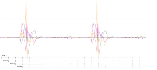
*How a gesture/movement is read on the serial plotter through its 3-axis accelerometer data
The original code from the tutorial was based on detecting a gesture the moment a significant motion is detected which could be a problem if we are trying to recognise more subtle gestures such as a slow hand waving or lifting the arm up slowly. I started experimenting with a couple of other ways for the arduino board to recognise a gesture at the ‘right’ time. First, I programmed a button where the wearer presses it to instruct the board to start recognising the gesture while it's being performed – this is not ideal as the wearer will have to consciously instruct the wearable whenever he/she is performing a gesture, but it allows me to understand what constitute a ‘right’ starting time to recognise a gesture. Lastly I tried programming the board to capture buckets of data at multiple short milliseconds time instances and run multiple analysis at once to compare each bucket and determine which bucket’s gesture at any instance returns the highest confidence level. However that does not return any significantly better result, it’s memory intensive for the board and reinforces the challenge, i.e. the machine needs to know when a person is not performing any gesture.
*Capturing buckets of data at multiple short milliseconds time
While the arduino board might be good at distinguishing between 2 gestures, if you perform a 3rd gesture that is untrained for the board, it will return either one of the learnt gestures with very low confidence level. This is because it was not taught with examples of other gestures. However, if we want it to learn a wearer’s behaviour over time, not only do we need to teach the machine with a set of gestures just like any language that comes with a strict set of components e.g alphabets, but it is equally important to teach it to recognise when the wearer is not doing anything significant. And with that it poses a major challenge, i.e. how much training do we need to teach a machine when the wearer is doing nothing?
Making Sense of the Nuances
When it comes to making sense of body gestures, our recognition of any gesture is guided by our background, culture, history, experience and interaction with each other. It is something that in this day and age, an advanced machine is still incapable of doing, e.g recognising different skin colours. Therefore, as much as we can train a machine to learn a body gesture through its x,y, z coordinates, or its speed of movement, we cannot train it with the cultural knowledge, experience or teach it to detect the subtle nuances of the meaning of a gesture (e.g the difference between crossing your arm when you are tired vs when you are feeling defensive).

Photo of one of the SUPERGESTURES workshops where young people design body gestures that can be detected by the wearable on their arm, and represent their story and vision of Manchester
It is worthwhile to remember that while this R&D project explores the extent to which machine learning can help create a discursive interaction between the wearer and the machine, there are limitations to the capability of a machine and it is important for us as designers and developers to help define a set of parameters that ensure that the machine can understand the nuances in order to create interaction that is meaningful for people of all backgrounds and colours.
While machine learning in other familiar fields such as camera vision do have some form of recognising “nothing” (e.g background subtraction), the concept of recognising “nothing” gestures (e.g should walking and standing up be considered ‘nothing’?) for wearable or body-based work is fairly new and has not been widely explored. A purely technological approach might say that ‘nothing’ simply requires adequate error-detection or filtering. But I would argue that the complexity of deciding what constitutes ‘nothing’ and the widely varying concept of what kinds of movement should be ‘ignored’ during training are absolutely vital to consider if we want to develop a wearable device that is trained for and useful for unique and different people. As this is work in progress, I will be experimenting more with this to gather more insights.
A blogpost by Ling Tan
#wearable technology#embodiedcompanionship#machinelearning#gesturerecognition#arduino#humanmachine#humandata#embodiedexperience#blog
0 notes
Photo

I've this board in a drawer from a lot. Now there is also the #sourcecode for #arduino IDE. ESP-EYE is a development board for image recognition and audio processing, which can be used in various #AIoT applications. It features an #ESP32 chip, a 2-Megapixel camera and a microphone. ESP-EYE offers plenty of storage, with an 8 Mbyte PSRAM and a 4 Mbyte flash. It also supports image transmission via Wi-Fi and debugging through a Micro-USB port. . . . . . . . . #Iot #facerecognition #camera #esp8266 #arduino #maker #smarthome #automation #robotics #engineering #electronics #vision #artificialvision #artificialintelligence #vision #smartvision #espressif https://www.instagram.com/p/CAI6tiKq3N4/?igshid=tvc7ugz8n31d
#sourcecode#arduino#aiot#esp32#iot#facerecognition#camera#esp8266#maker#smarthome#automation#robotics#engineering#electronics#vision#artificialvision#artificialintelligence#smartvision#espressif
0 notes
Text
Wireless Glove for Hand Gesture Acknowledgment: Sign Language to Discourse Change Framework in Territorial Dialect- Juniper Publishers

Abstract
Generally deaf-dumb people use sign language for communication, but they find it difficult to communicate in a society where most of the people do not understand sign language. Due to which communications between deaf-mute and a normal person have always been a challenging task. The idea proposed in this paper is a digital wireless glove which can convert sign language to text and speech output. The glove is embedded with flex sensors and a 9DOF inertial measurement unit (IMU) to recognize the gesture. A 9-degree of freedom inertial measurement unit (IMU) and flex sensors are used to track the orientation of fingers and motion of hand in three dimensional spaces which senses the gestures of a person in the form of bend of fingers and tilt of the hand fist. This system was tried for its practicality in changing over gesture based communication and gives the continuous discourse yield in local dialect and additionally shows the text on GLCD module. The text show being in English, the voice yield of the glove will be in provincial dialect (here Kannada). So this glove goes about as a communicator which in part encourages them to get their necessities and an interpreter giving greater adaptability in correspondence. In spite of the fact that the glove is planned for gesture based communication to discourse transformation, it is a multipurpose glove and discovers its applications in gaming, mechanical autonomy and therapeutic field.In this paper, we propose an approach to avoid the gap between customer and software robotics development. We define a EUD (End-User Development) environment based on the visual programming environment Scratch, which has already proven in children learning computer science. We explain the interests of the environment and show two examples based on the Lego Mindstorms and on the Robosoft Kompai robot.
Keywords: Sign Language; Flex Sensors; State Estimation Method; 3D Space; Gesture Recognition
Abbrevations: ANN: Artificial Neural Networks; SAD: Sum of Absolute Difference; IMU: Inertial Measurement Unit; ADC: Analog to Digital Converter; HCI: Human Computer Interface
Introduction
About nine thousand million people in the world are deaf and mute. How commonly we come across these people communicating with the normal world? The communication between a deaf and general public is to be a thoughtful issue compared to communication between visually impaired and general public. This creates a very small space for them as communication being a fundamental aspect of our life. The blind people can talk freely by means of normal language whereas the deaf-mute people have their own manual-visual language popularly known as sign language [1]. The development of the most popular devices for hand movement acquisition, glove-based systems started about 30 years ago and continues to engage a growing number of researchers. Sign language is the non-verbal form of intercommunication used by deaf and mute people that uses gestures instead of sound to convey or to express fluidly a speaker’s thoughts. A gesture in a sign language is a particular movement of the hands with a specific shape made out of them [2]. The conventional idea for gesture recognition is to use a camera based system to track the hand gestures. The camera based system is comparatively less user friendly as it would be difficult to carry around.
The main aim of this paper is to discuss the novel concept of glove based system that efficiently translates Sign Language gestures to auditory voice as well as text and also promises to be portable [3]. Several languages are being spoken all around the world and even the sign language varies from region to region, so this system aims to give the voice output in regional languages (here Kannada). For Sign language recognition few attempts have been made in the past to recognize the gestures using camera, Leaf switches and copper plates but there were certain limitations of time and recognition rate which restricted the glove to be portable. Mainly there were two well-known approaches viz. Image processing technique and another is processor and sensor based data glove [4]. These approaches are also known as vision based and sensor based techniques. Our system is also one such sensor based effort to overcome this communication barrier, which senses the hand movement through flex sensors and inertial measurement unit and then transmits the data wirelessly to the raspberry pi which is the main processor, that accepts digital data as input and processes it according to instructions stored in its memory, and outputs the results as text on GLCD display and a voice output.
Background Work
People who are hard of hearing or quiet are isolated in the cutting edge work environment as well as in regular daily existence making them live in their own different networks. For example, there have been enhancements in amplifiers and cochlear inserts for the hard of hearing and counterfeit voice boxes for the quiet with vocal rope harm. Be that as it may, these arrangements don’t come without drawbacks and expenses [5]. Cochlear inserts have even caused a tremendous debate in the hard of hearing network and numerous decline to considerably think about such arrangements. Thusly, we trust society still requires a compelling answer for expel the correspondence obstruction between hard of hearing and quiet people and nonmarking individuals. Our proposed arrangement and objective is to plan a Human Computer Interface (HCI) gadget that can make an interpretation of gesture based communication to content and discourse in provincial dialect, furnishing any hard of hearing and quiet people with the capacity to easily speak with anybody [6]. The thought is to plan a gadget put on a hand with sensors fit for assessing hand signals and after that transmitting the data to a preparing unit which plays out the communication via gestures interpretation. The last item will have the capacity to proficiently perform gesture based communication and give the focused on yield. We want to have the capacity to enhance the personal satisfaction of hard of hearing and quiet people with this gadget.
Comparison of Background Related Work
(Table 1)
Problem Definition
With a population of around 7.6 billion today communication is a strong means for understanding each other. Around nine thousand million individuals are deaf and mute. Individuals with discourse hindrance their vocal articulation are not reasonable, they require a specific skill like static state of the hand orientation to give a sign, more as manual-visual dialect prevalently known as sign language to communicate with general population. They think that it’s hard to impart in a general public where a large portion of the general population don’t comprehend sign language. Hence forth they find a little space to convey and do not have the capacity to impart at a more extensive territory [7].
Literature Survey
The system investigates the utilization of a glove to give communication via gestures interpretation in a way that enhances the techniques for previous plans. Few university research has taken an activity to make prototype devices as a proposed answer for this issue, these devices focus on reading and analyzing hand movement. However, they are lacking in their capacity to join the full scope of movement that gesture based communication requires, including wrist revolution and complex arm developments (Table 2).
Proposed System
(Figure 1)
Block Diagram Explanation
The sensor based system is designed using four 4.5 inch and two 2.2-inch flex sensors which are used to measure the degree to which the fingers are bent. These are sensed in terms of resistance values which is maximum for minimum bend radius. The flex sensor incorporates a potential divider network which is employed to line the output voltage across 2 resistors connected as shown in Figure 2.
The output voltage is determined using the following equation,
Where;
R1 - flex sensor resistance. R2 - Input resistance.
The external resistor and flex forms a potential divider that divides the input voltage by a quantitative relation determined by the variable and attached resistors. For particular gestures the current will change, as a result of the changing resistance of the flex sensor which is accommodated as analog data. One terminal of flex sensor is connected to the 3.3Volts and another terminal to the ground to close the circuit. A 9-Degree of Freedom Ardu Inertial Measurement Unit (IMU) is essential for accelerometer and gyroscope readings which is placed on the top of the hand to determine hand position. The co-related 3D coordinates are collected by the inertial measurement unit as input data [8]. The impedance values from flex sensors and IMU coordinates for individual gesture are recorded to enumerate the database. The database contains values assigned for different finger movements. When the data is fed from both flex sensors and IMU to Arduino nano it will be compute and compare with the predefined dataset to detect the precise gesture and transmitted wirelessly to the central processor i.e. raspberry pi via Bluetooth module. Raspberry Pi 3 is programed to display text output on GLCD. Graphic LCD is interfaced with the Raspberry pi3 using 20-bit universal serial bus in order to avoid bread board connection between processor and the display, and a 10Kohm trim potentiometer is used to control the brightness of display unit. Further to provide an auditory speech, pre-embedded regional language voice is assigned for each conditions as similar to the text database which is mapped with the impedance values. Two speakers are used with single jack of 3.5mm for connection and a USB to power-up the speakers [9]. When text is displayed, the processor will search for the voice signal which will be transmitted through speakers.
Methodology (Figure 3)
a) The gesture is served as an input to the system which is measured by both the sensors particularly from the f lex sensor in terms of impedance and the IMU gives the digital values.
b) These values from the flex sensor are analog in nature and is given to the Arduino nano which uses the analog to digital convertor consolidated in it to convert the resistive values to digital values.
c) IMU utilizes the accelerometer/gyroscope sensors to measure the displacement and position of the hand.
d) These qualities from both the sensors are fed to Arduino nano which contrasts it and the values stored in the predefined database, and further transmits this digital data wirelessly to the main processor by means of Bluetooth.
e) Central processor the raspberry pi3 is coded in python dialect for processing the received digital signals to generate the text output, for example, characters, numbers and pictures. Further, the text output is shown on Graphic-LCD display and next text to speech engine, here particularly espeak converter is utilized to give the soundrelated voice output [10].
Finally, system effectively delivers the output as text and auditory voice in regional dialect.
Prototype Implementation and its Working
In this system, the features are extracted from the hardware sensor inputs and the targets are the words in sign language. To realize the design requirements, several hardware components were considered during prototyping. Much of the hardware was selected due to their ease of use and accuracy. The Ardu 9DOF IMU was selected for convenience as it produces the computation necessary for linear acceleration and gyroscopic measurements. The roll, pitch and yaw measurements were found to be roughly ±2° accuracy which is far beyond sufficient for our sign language requirements. Since the flex sensor required additional analog pins, careful planning allowed us to fit the circuit in an agreeable manner on the hand glove. Space was managed to add in the HC05 Bluetooth module onto the device. All the sensors must be placed in a way as to not make contact with each other causing short circuits which and disruption of measurement readings [11]. Electrical tape was necessary to provide insulation for our sensors. The system recognizes gestures made by the hand movements by wearing the glove on which two sensors are attached, the first sensor is to sense the bending of five fingers, the flex sensor of 2.2 inches for thumb and for the other four fingers of 4.5 inches and the second sensor used is 9-DOF Inertial Measurement Unit to track the motion of hand in the three-dimensional space, which allows us to track its movement in any random direction by using the angular coordinates of IMU (pitch, roll and yaw). Since the output of f lex sensor is resistive in nature the values are converted to voltage using a voltage divider circuit.
The resistance values of 4.5-inch flex sensors range from 7K to 15K and for 2.2-inch flex sensor, it ranges from 20K to 40K, as shorter the radius the more resistor value. Another 2.5K ohm resistor is utilized to build a voltage divider circuit with Vcc supply being 3.3volts taken from Arduino nano processor, the voltage values from the voltage divider circuit being analog in nature are given to the Arduino nano processor which has an inbuilt ADC [12]. Further, the IMU senses the hand movements and gives the digital values in XYZ direction called the roll, yaw, pitch respectively. The values from the IMU and values of the flex sensors are processed in the Arduino nano which is interfaced with HC-05 Bluetooth module embedded on the glove which provides the approximate range of 10 meters. The data processed in nano are sent wirelessly through Bluetooth to the central processor i.e. Raspberry Pi which is coded in python, in a way to convert given values into the text signal by searching in database for that particular gesture. In accordance with the digital value received, the impedance values along with 3 dimensional IMU coordinates for each individual gestures are recorded to enumerate the database. The database contains collective resistance values assigned for different finger movements. When the computed data is received by the processor, it is compared with the measured dataset to detect the precise gestures. If the values matches, then the processor sends the designated SPI commands to display the texts according to gestures onto the GLCD and the espeak provides the text to speech facility giving audible voice output in regional language through the speakers. Further, for any next gestures made, both flex sensor and IMU detects and data is compared with the database already present in the processor and if it matches, displays in text format as well as audible output speech will be given by the speakers [13] (Figure 4).
Results
In this prototype system, the user forms a gesture and holds it approximately for 1 or 1.5 seconds to ensure proper recognition. Each gesture comprises of bending of all fingers in certain angles accordingly. Every bend of the sensor (finger) produces unique ADC value so that when different hand gesture is made, different ADC values are produced. Taking such ADC values for 4 different users, a table of average ADC values for each sensor is maintained where F1, F2, F3, F4 and F5 represents the little finger, the ring finger, the middle finger, the index finger and thumb respectively. Table 3 shows the gestures and corresponding words voiced out. The hand signs taken in the prototype can be easily modified using the concept of ADC count according to the user convenience. At the same time the voice output can be changed easily to gives a flexibility in change of language according to different regions (Figure 5).
Applications
a) Voice interpreter for mute people
b) No touch user interface
c) Gaming industry: Hand gestures play a vital role in the gaming industry, especially in first person shooting games. The player can control the character in the game using his hand and this could give a real life experience of the game. Also, virtual reality is gaining grounds in the gaming industry. Combining virtual reality with the gloves with a haptic feedback can give the gamer a real life gaming experience.
d) Controlling a robotic arm using the gloves: The gloves could be used to control a robotic arm. The applications for this system are wide. With incorporation of haptic feedback, the glove -robotic arm interface could also be used in bomb diffusion.
e) Remote medical surgery: In this the surgeon need not be at the physical location to perform the surgery. He could control a robotic arm remotely to perform the surgery and a haptic feedback could give him the feel of actually performing the surgery. But this would require the gesture recognition to be very precise and the transfer of data from the hand to the robotic arm should be without even a tiny glitch.
Advantages
a) Cost effective light weight and portable
b) Real time translation approximately in no time delay
c) Flexible for ‘N’ users with easy operation
d) Fully automate system for mute communication
Future scope
a) The system can be further developed with Wi-Fi connection and enlarged database supporting special characters or symbols.
b) Microsoft Text To Speech (TTS) engine can be utilized to provide compatibility for multiple international languages.
c) An Android application can be developed for displaying the text and speech output on an Android device.
Conclusion
As we discovered that Deaf-quiet individuals utilize communication via gestures to cooperate with others however numerous don’t comprehend this motion dialect. We have built up a sensor based motion acknowledgment framework to undercover signal into local dialect discourse and content yield. In this framework the hard of hearing quiet individuals wear the gloves to perform hand motion, the transformation of content to discourse in provincial dialect and show has been seen to be predictable and dependable. In this way, the proposed framework with the database of 20 words and 15 sentences has been effectively created which changes over the motions into English words or sentences and shows the yield on GLCD and relating voice yield in provincial dialects using espeak. The proposed framework has insignificant equipment mounted on it which makes it dependable, convenient and savvy and more straightforward to speak with the general public [14]. One more requesting where this framework could be utilized as a part without bounds: Helping hand for individuals with Cerebral Palsy; Cerebral palsy usually appears in early childhood and involves a group of permanent movement disorders. The symptom varies with people and often includes poor coordination, stiff muscles, weak muscles, and tremors. Also, the problems with sensation, vision, and hearing, swallowing and speaking have been identified as other symptoms [15,16]. This problem can be solved to a great extent by providing them with a provision to communicate with just a single finger. The frequently used words by such people can be put across to people with just a small movement in the finger and using our state estimation technique it could predict the letters or words [17].
For More Open Access Journals Please Click on: Juniper Publishers
Fore More Articles Please Visit: Robotics & Automation Engineering Journal
#Juniper Publishers#Open Access Journals#Robotics#Neural Networks#Fuzzy logics#Artifical Intelligence
0 notes
Text
Introduction
With the advancement of computer graphics technology, landscapes and games that can be seen with reality are becoming more familiar, and technologies for bridging the world with reality are also VR (Virtual Reality), AR (Augumented Reality), or MR (Mixed Reality). In general, VR is a technology that cuts off the real landscape by wearing dedicated goggles, and is a technology that more immerses the world. Specifically, it displays images on a panel inside the goggles and sees them with both eyes. By projecting images with parallax, you can get a real sense of depth and stereoscopic effect, but on the other hand, you can not have real eyes, pan-focus images (all in focus), The reality is that it is a video game with a fixed focus at a certain distance. It has been announced that major IT companies such as Google, Facebook, and VR manufacturer Oculus are researching and developing this issue.
youtube
How our eyes see the world?
In fact, how do our eyes perceive the world? When we look around, we feel that everything around us is in focus, but theoretically it is impossible. If our eye lens is a pinhole, it is not possible in principle, but in fact it is not. There are parallaxes depending on the positions of the left and right eyes, but usually they do not look double. This seems to be a state in which the correction is quite effective due to the complementary function of the brain. Similarly, it may be due to the function of the brain that colors appear to change, such as optical illusions, or that still images appear to move.
In the case of VR, the screen that displays the image is only a few centimeters from the lens surface of the eye. By viewing the image through a convex lens, you can see a landscape that expands to the full field of view, but the focal point is on the screen plane, so a strange situation arises where the focal point is close to what should have been seen far away. The eye obtains information not only by binocular parallax and aerial perspective recognition, but also by the degree of lens adjustment (muscle tension), so the visible image and the actual physical (physical) information This divergence appears in the form of so-called VR sickness.
When our eyes see an object, they try to focus instantly, but what is needed in that case is a landmark for focusing. It may be a part of an object, or a wall pattern or scratch can be clearly recognized. However, in the case of a wire mesh fence or a repetitive pattern on the wall, the two patterns (graphics) are focused on the left and right sides, and the perspective may not match. In addition, there is a phenomenon that it is difficult or impossible to grasp the distance on a white shining wall without shadows or patterns because there is no mark for measuring the distance.
CG space and focus
On the other hand, in the CG space, setting of the camera (focal length) is arbitrary. In other words, with pan focus, the lens can be focused from near the lens surface to infinity, and can be freely set to focus at a certain distance from the center by setting the depth of field and focal length. In CG animation etc., the focus can be arbitrarily changed according to the scene and camera movement, but it is difficult to set the distance to the object to be focused when the angle of view moves in real time such as VR . Therefore, based on one hypothesis, we will experiment with the autofocus function in VR space in a relatively easy way.

Principle and experiment of autofocus function
The open source 3D software “Blender” was used as an experimental environment. This software is very suitable for such experiments because it is quite powerful for modeling and animation production, and it is easy to control objects with Python.
The program is divided into two parts. One is to import the orientation of the headset (goggles) into Blender via serial communication. The other is focus control. I made a simple headset this time, but with two square LCDs and a 6-axis gyro sensor and Arduino for communication, I decided to send the video via an HDMI cable and serial communication via a USB cable. . From the gyro sensor, the value is taken in as a quaternion value using an internal library. In normal (X, Y, Z), the error when returning the direction was large, and the correct direction could not be obtained. The problem of orientation was solved by taking in the quaternion and controlling it with that value.
The second part, consider the focus issue. As described earlier, the camera settings in CG are free. The focus can be set even in the “empty space” that our eyes cannot do. So where do you focus on the screen you are looking at? Some major IT companies are researching methods to check where they are currently looking on the screen by eye tracking in goggles and focus on it. There are doubts about how. This is because people are not looking at moving their eyes only, but they must always turn their faces to accurately capture the object. In that case, the object is always near the center of the field of view. Then, it is possible to focus on an object near the center of the current field of view.
The problem is how to detect objects in the currently displayed screen (view). In addition, the focus is on the detected object. The first problem is that by entering the coordinates of the object using the commands in Blender's API (Application Programming Interface), the position in the current view can be obtained. The second problem is a little tricky. Given a large building and a small apple in front of it, the apple can be in the center of the object. Depending on the distance to the camera, the difference in the distance between the apple's sticky part and the front skin part is very small, but the distance between the center of the building and the door, rooftop edge, window frame, etc. is very large. It is impossible to detect at the center of the building. It is possible to detect the position not only at the center of the object but also at the vertex of the object or the center of the polygon. However, in the case of a complicated curved surface, the number of polygons may become enormous and the detection may take too long. is there. In the first place, when our eyes focus on an object, it seems that they are looking for some feature point. For example, it is a flower that blooms in a tree, or a part that has a distinct characteristic such as a cloud, a corner of a building, or a window frame. Then, I thought that the most efficient method would be to place an object just for that purpose at the part where the target object is focused and detect them. In other words, special objects for position detection are arranged at corners of buildings, door windows (window frames), corners and centers of posters affixed to walls, and only these are checked. A special object called “Empty” was used as the special object. Empty has no actual shape, only information such as position, size, and angle. Three lines in the XYZ direction can be seen on the screen, but they are not displayed at the time of rendering or can be hidden, so there is no hindrance to the expression. These are checked in the loop of the program, and those existing in the target area are picked up and listed. As a next step, if the camera is set as the distance to focus on the object closest to the camera among the objects in the list, it will be in focus. These functions were written and executed as Python code. As the display method, Blender version 2.8 (beta) EEVEE was used, but this function is effective for future video expression and experiments because high-quality images can be obtained in real time without time-consuming ray tracing rendering.
As a result of the experiment, very good results were obtained. Since the lens is not mechanically moved like the autofocus function of a digital camera, the focus can be switched instantaneously. The focus can be switched in the same manner even if the camera is moved or the empty object is linked and moved. If there is no object to be focused in the view, it is programmed to be set to infinity, so the image pasted on the background is focused. As a disadvantage of this experiment, the density of information from the gyro sensor is coarse and the tracking of the camera is coarse. In addition, there are many unexamined parts, such as how to avoid performance degradation when detecting a larger amount of empty.
[ Prototype 1 ]


youtube
[ Prototype 2 ]


youtube
[ Prototype 3 ]


youtube
youtube
[ Prototype 4 (on going) ]

0 notes
Text
Who’s a good AI? Dog-based data creates a canine machine learning system
We’ve trained machine learning systems to identify objects, navigate streets, and recognize facial expressions, but as difficult as they may be, they don’t even touch the level of sophistication required to simulate, for example, a dog. Well, this project aims to do just that — in a very limited way, of course. By observing the behavior of A Very Good Girl, this AI learned the rudiments of how to act like a dog.
It’s a collaboration between the University of Washington and the Allen Institute for AI, and the resulting paper will be presented at CVPR in June.
Why do this? Well, although much work has been done to simulate the sub-tasks of perception like identifying an object and picking it up, little has been done in terms of “understanding visual data to the extent that an agent can take actions and perform tasks in the visual world.” In order words, act not as the eye, but as the thing controlling the eye.
And why dogs? Because they’re intelligent agents of sufficient complexity, “yet their goals and motivations are often unknown a priori.” In other words, dogs are clearly smart, but we have no idea what they’re thinking.
As an initial foray into this line of research, the team wanted to see if by monitoring the dog closely and mapping its movements and actions to the environment it sees, they could create a system that accurately predicted those movements.
In order to do so, they loaded up a malamute named Kelp M. Redmon with a basic suite of sensors. There’s a GoPro camera on Kelp’s head, six inertial measurement units (on the legs, tail, and trunk) to tell where everything is, a microphone, and an Arduino that tied the data together.
They recorded many hours of activities — walking in various environments, fetching things, playing at a dog park, eating — syncing the dog’s movements to what it saw. The result is the Dataset of Ego-Centric Actions in a Dog Environment, or DECADE, which they used to train a new AI agent.
This agent, given certain sensory input — say a view of a room or street, or a ball flying past it — was to predict what a dog would do in that situation. Not to any serious level of detail, of course — but even just figuring out how to move its body and where to is a pretty major task.
“It learns how to move the joints to walk, learns how to avoid obstacles when walking or running,” explained Hessam Bagherinezhad, one of the researchers, in an email. “It learns to run for the squirrels, follow the owner, track the flying dog toys (when playing fetch). These are some of the basic AI tasks in both computer vision and robotics that we’ve been trying to solve by collecting separate data for each task (e.g. motion planning, walkable surface, object detection, object tracking, person recognition).”
That can produce some rather complex data: for example, the dog model must know, just as the dog itself does, where it can walk when it needs to get from here to there. It can’t walk on trees, or cars, or (depending on the house) couches. So the model learns that as well, and this can be deployed separately as a computer vision model for finding out where a pet (or small legged robot) can get to in a given image.
This was just an initial experiment, the researchers say, with success but limited results. Others may consider bringing in more senses (smell is an obvious one) or seeing how a model produced from one dog (or many) generalizes to other dogs. They conclude: “We hope this work paves the way towards better understanding of visual intelligence and of the other intelligent beings that inhabit our world.”
from RSSMix.com Mix ID 8176395 https://techcrunch.com/2018/04/11/whos-a-good-ai-dog-based-data-creates-a-canine-machine-learning-system/ via http://www.kindlecompared.com/kindle-comparison/
0 notes
Text
Which type of robot gifts are best for your child?
Did you know we received the word robot from the Czech word “robotnik” meaning slave? The word is fitting for the machines we’ve asked to endlessly compute algorithms for us and clean our floors. But exactly what a robot is has evolved from the days when robots were largely factory drudges. These days, robots can be as cute as pets, as efficient as a nurse or frightening enough to raise ethical questions. There are telepresence robots that we can send to work for us, humanoid robots that send us chillingly into the uncanny valley and of course, beer serving robots who are our friends in our laziest times. Love them or fear them, we are a civilization obsessed with robots. So, I’m willing to bet you know more than one or two geeks in your life who would appreciate a robot themed gift this holiday season. Check out our epic list of ultimate robot gifts for the holidays: remote control car with night vision https://www.robotsden.com/best-remote-control-car-with-night-vision
1. Recycled Robot Ornaments
These little industrial ornament robots measure just 4-5″ tall and are completely eco-friendly, repurposed and up-cycled from salvaged, sawed and sanded lumbar scraps, scrap metal aluminum, recycled washers, nuts bolts, tacks, etc. The robots are spray-painted in red and speckled with cream paint. To preserve the industrial look, robots are partially painted with “dirty”-looking components, like nuts or washers.
2. My Robot Nation- Design Your Own Robot Collectible
My Robot Nation launched last week with an extremely cool way to model and 3D print your own robot collectible on the Web, with 9 billion possible combinations. Your robot is printed in full-color and it’s delivered to your doorstep. Check out the site’s limited edition holiday themes for your robot and the ability to send gift codes to others so they can design their own robot army at any time.
3. Romo: The Smartphone Robot
Romo is a smartphone robot, or a physical platform that turns your smartphone into a robot, developed by Romotive, a.k.a Peter Seid and Phu Nguyen. After a wildly successful Kickstarter campaign, the gents will be able to build their new robotics platform, which adds everything that the smartphone is missing like movement, accessories and the physical capabilities that a true robot needs.
“Unlike the lame single-purpose machines out there for sale today, our robots will also be able to learn, grow, and change, both by adding new hardware modules to the platform, and more importantly, by bring to people everywhere a true “app store” for robots, where robots can quickly gain functionalities based on the app they are running (and you can even code your own).” Do Robotic Pool Cleaners Really Work https://www.robotsden.com/do-robotic-pool-cleaners-really-work
4. Robot 99 iPad 2 Cover
This beautifully made leather case is specifically designed for the iPad 2 and includes a flip stand, built-in magnetic closure and a camera hole cutout on the back with full access to all iPad 2 ports/connections.
5. Parrot AR.Drone QuadriCopter
The AR.Drone remote-control quadricopter can be controlled from the palm of your hand. This robot is packed with smart technology including two cameras, front-facing and bottom-facing, which stream live video to the screen of your tablet or smartphone. The AR.Drone can also be used in video games, such as AR.FlyingAce, a dogfight between two AR.Drones. Or you can just take it to the park and bother local hipsters on a sunny day.
6. Sphero
While Sphero won’t ship til January 2012, this robo-present will be well worth the wait. Sphero is the first robotic ball that you control with a tilt, touch, or swing from your smartphone or tablet. Sphero comes with single and multi-player games that blend play into the virtual and real worlds. The company says, “It’s the ball evolved.”
7. Robot Tea Infuser
Who needs tea pots when you can have a tea-bot!? As a tea drinker with a robot obsession, this tea infuser had me at first sight. The retro robot comes with curving hinged arms that cling to the rim of your tea mug. To add tea, open up the bot by twisting its antennas. Once in hot water, the tea flavor flows through the perforations on both sides of its metal body. The robot tea infuser comes with a coordinating silver tray. Unfortunately, the clear mug doesn’t come with the infuser, so you’ll have to pick one up separately to show off your tea-bot. arduino robot arm source code https://www.robotsden.com/7-arduino-robotic-arm-project-ideas-tutorial-plus-source-code
8. Wind-Up Salt and Pepper Robots
“Oh excuse me, could you please pass the salt?” has never been more fun than with these robotic salt and pepper shakers. Just wind them up and point them in the right direction to impress your salivating guest.
8. Pleo Dinosaur Robot
Pleo, built by Emeryville, Calif.-based UGOBE, is a robotic replica of a one-week old Camarasaurus, a dinosaur from the late Jurassic period. The popular toy bot is the exact height of its pre-historic counterpart, learning and reacting to human touch. That strikingly lifelike behavior is the result of eight skin sensors, two microphones and an infrared and camera-based vision system. Pleo is cheaper than a puppy, doesn’t need to be walked, doesn’t trigger allergies and is more affectionate than the average cat. (N.B. Pleo does not like this upside down position.)
9. WowWee’s Femisapien
Femisapien is WowWee’s gynoid model, which comes with a dash of artificial intelligence that any woman can admire. At just 9″ tall, Femisapien moves more fluidly than her male counterpart Robosapien and responds to touch, light and sound. The fembot can be programmed to perform routines of movements up to 80 steps long including dancing, waving and blowing kisses. She introduces herself, performs comedy routines, even hands out business cards. Femisapien can also control other WowWee robots like Robosapien via her infrared sensors. Talk about technology liberating women. best robot toys for 10 year olds https://www.robotsden.com/best-robot-toys-for-10-year-old
10. Thing-O-Matic
MakerBot is a New York based startup that sells 3D printers, or “robots that make things”. The Makerbot has spawned a 3D printing revolution, dropping the price point on machines that cost tens of thousands of dollars to a paltry $750. Its newest product is the MakerBot “Thing-O-Matic,” which debuted at last year’s Maker Faire, is a 3D printer assembly line, printing item after item of thing after thing.
11. Bennett Robot Works
These industrial, handmade robots are made by local New York artist Gordon Bennett. Inspired by industrial designers Norman Bel Geddes and Raymond Loewy whose visions shaped the “Modern Age” of the 1940s and 1950s. Bennett’s robots are made from a variety of materials– some new and some found in junkyards. Each robot takes one month to build. These robots are quite serious works of art, not toys.
12. Rock Star Robot
This 4-foot tall Rock Star Robot is handmade from vintage picnic jugs, coffee thermoses, old vacuum cleaner tubes and other found objects. Like Bennett’s bots, this is no kids toy; the Rocking Robot, which doubles as an overgrown nightlight, is an artful study of mid-20th century American culture and design that will cost you more than what you’ve got on the floor of your front hall closet. Combining influences from rock ‘n’ roll, science fiction and the sleek “futuristic” design style of the era, artist Toby Fraley turns his own childhood love of robots into a unique work of art. are robotic pool cleaners worth it https://www.robotsden.com/do-robotic-pool-cleaners-really-work
13. Willow Garage’s PR2 Robot
One day, the roboticists at Willow Garage were thirsty, so they decided to teach their quick-learning PR2 robot a few tricks. When you want a beer, you just have to open a web interface, choose your preferred brew, and click the “Beer Me” button. The PR2 opens the refrigerator, scans its contents using image recognition software and retrieves a bottle of the correct kind, then brings it back to you. It can open the bottle as well. PR2 also knows how to fold laundry and play pool. Don’t want to buy a brand new robot? Check out eBay’s vintage offerings for robots from the past here. And if you know of any awesome robot themed gifts we missed, please let us know in the comments!
1 note
·
View note
Text
August 08, 2019 at 10:00PM - The Complete Robotics eBook Bundle (90% discount) Ashraf
The Complete Robotics eBook Bundle (90% discount) Hurry Offer Only Last For HoursSometime. Don't ever forget to share this post on Your Social media to be the first to tell your firends. This is not a fake stuff its real.
Robot Operating System, or ROS, is one of the most popular software frameworks for modeling, simulating, and prototyping robots; but it can be tricky for newcomers. Loaded with more than 14 ROS projects, this eBook will help you get your feet wet as you walk through building a self-driving car, creating an autonomous mobile robot, and even tinkering around with image recognition and deep learning.
Access 452 pages of content 24/7
Deepen your understanding of ROS & walk through hands-on-projects
Explore building a self-driving car, autonomous robot & more robotic creations
Learn about image recognition & deep learning and how they apply to robotics
Building and programming a fully functional robot sounds complicated, but Robot Operating System (ROS) makes it much simpler. Ideal for ROS newbies, this eBook is packed with This book is packed with hands-on examples that will help you program your robot and give you complete solutions using open source ROS libraries and tools. You’ll start with the ROS basics, then move on to sensors and actuators, navigation, mapping, and more until you’re ready to create your own robot.
Access 468 pages of content 24/7
Understand the ROS essentials & dive into command-line tools, visualization GUIs, and more
Learn how to connect robot sensors & actuators to ROS
Discover how to obtain & analyze data from cameras and 3D sensors
Learn how to design a robot that can map its environment & navigate autonomously
Famously functional and used at virtually every level in the robotics field, Robot Operating System, or ROS, is a worthwhile addition to your robotics toolbox. Updated to the Kinetic Kame release, this second edition of ROS Robotics will help you come to grips with ROS’ new features as you walk through step-by-step examples, including manipulator arms and flying robots. By the end of the eBook, you’ll have concrete experience controlling robots with ROS.
Access 484 pages of content 24/7
Familiarize yourself w/ the ROS essentials
Walk through simulating & controlling a robot arm
Control a flying robot
Learn how to send your robot on an independent mission
Deepen your understanding of controlling robots w/ external devices
Your Robot Operating System (ROS) education wouldn’t be complete without this comprehensive eBook. Focusing on the Kinetic Kame ROS release, this eBook discusses advanced concepts you’ll need to know when programming with ROS. You’ll learn how to build models of complex robots and simulate and interface them using the ROS MoveIt! motion planning library and ROS navigation stacks.
Access 580 pages of content 24/7
Create a robot model with a robotic arm & a differential wheeled robot
Use SLAM & AMCL packages to create robots that can navigate autonomously
Deepen your understanding of I/O boards, like Arduino, robot sensors & high-end actuators
With powerful processing and storage capabilities, the ESP8266 Wi-Fi module is ideal for just about any Internet-connected project. This eBook covers robotics projects based on the original ESP8266 microcontroller board and some variants of ESP8266 boards. You’ll start with a look at setting up your development environment with basic hardware and software components. Then, you’ll learn how to use various chassis kits, motors, power supplies, sensors, and more to build Wi-Fi-controlled robotics projects.
Access 208 pages of content 24/7
Learn how to build a basic robot with the original ESP8266 & other boards
Walk through building a line-following robot by connecting line sensors
Learn how to control a Robot with a Wiimote
Explore building a mini robot rover chassis & control it via Wi-Fi
Dive into creating a robot that can take pictures
from Active Sales – SharewareOnSale https://ift.tt/2GdiJ9J https://ift.tt/eA8V8J via Blogger https://ift.tt/2M6CyBC #blogger #bloggingtips #bloggerlife #bloggersgetsocial #ontheblog #writersofinstagram #writingprompt #instapoetry #writerscommunity #writersofig #writersblock #writerlife #writtenword #instawriters #spilledink #wordgasm #creativewriting #poetsofinstagram #blackoutpoetry #poetsofig
0 notes