#arduino hardware
Explore tagged Tumblr posts
Visit Tumblr Blog
Explore Tumblr blogs with no restrictions, modern design and the best experience.
Last Seen Tumblr Blogs


Fun Fact
Tumblr has been providing a Korean-language service since 2013.
Text
hiiiii
tested an ips tft display i have since ahh... spring. not so long ago ive got an idea to embody a scene from 8:11, when ryker got splashed with blood at the screen with leon.


its a wip now but i hope i would not be eaten by exams due this week..


heres more photos of display, but now in a dark.
less interesting - while writing the code it turned out that i didnt have the library i needed, which wasn't even in the built-in ide library search. so i went to github, and there it turned out that the library was outdated and in its place there was a new one (since 2020 ig), the version of which was already downloaded. i had to download the archive and upload it to ide to make everything work. also, i need to edit the program a little and clean it from unnecessary #includes, so there is no confusion.. and i also used a breadboard

#richterursidae#811#811 game#811 leon#811 leon tremblay#eight eleven#leon tremblay#arduino#hardware#electronics#electronics hobby#computing#arduino projects#is this that necessary to put so many tags?#anyways sorry for my uhh english it isnt my first language#im also bilingual
88 notes
·
View notes
Text

QT adapter for Sensirion SEN6x 🔌🌡️
Sensirion just came out with the new SEN6x series of 'everything including the kitchen sink' environmental sensors - and you can pick them up at DigiKey right now
https://www.digikey.com/short/c4tndnd4
We noted that the cable for the 6 series is the same as the SEN5x, BUT power supply requirements differ, so our existing SEN5x adapter won't work
Here's a simple level-shifting breakout that converts to the JST GH cable connector
#sensirion#sen6x#environmentalsensors#qtadapter#electronics#sensorintegration#adafruit#digikey#makers#engineering#iot#smarthome#arduino#raspberrypi#hardware#electronicsprojects#sensortech#embedded#robotics#opensource#innovation#techgadgets#powerconversion#jstgh#programming#linux#python#java#software engineering#coding
9 notes
·
View notes
Text
need a bit of advice on something rather new to me... i have been DYING to get into some semblance of diy electronics/robotics, specifically regarding the idea of building a flipper zero knockoff with a raspberry pi/esp32/arduino. or a hack rf one ripoff, etc. u get it? i wanna make a lil handheld pwnagotchi pet style device for rolljam rf shit, something that can copy and paste and send and receive rf signals, but homemade by my self....
please if anyone has experience, resources, ideas, anything at all= hit me up right now immediately asap today please.... i am so passionate and ready to do this please help me make device go beepboop
#flipper zero#hack rf one#raspberry pi#esp32#arduino#diy electronics#diy#diy hacking#car hacking#hacking hardware#hacking#help#hacking help#hacking question#need advice#diy projects#diy craft#diy punk#upcycle#homebrew
14 notes
·
View notes
Text
So I was hyperfocused on clock module concept the back half of this week, so I started coding some stuff up. This afternoon, I think I stumbled onto a timer compare value that let's me just increment the master clock by the bpm value without any scaling. Sounds fake, but okay...
(maybe longer post later breaking down the code)
#i still gotta math it out more and run some simulations and hardware tests#but it seems pretty straightforward at this point#synth diy#sdiy#arduino
4 notes
·
View notes
Text
USB-BLE MIDIインターフェイスを作る② - iOSのBLE MIDI接続設定を調べる
USB-BLE MIDIインターフェイスを作る際に気になる遅延とiOSの接続設定の話です。
前回のお話:
無線MIDI接続を利用する際に気になってしまうのが反応の鈍さではないでしょうか。鍵盤を押してから音が鳴るまでに一瞬でも間があったり、ジャストなタイミングで弾いているはずなのになぜか音がずれる、的なことがあると致命的です。
BLEの技術的な話
Bluetooth LE(BLE)では、親機(セントラル)と子機(ペリフェラル)という概念があり、たとえばiOS機器とBLE MIDI機器を接続する場合はiOS側がセントラル、BLE MIDI機器がペリフェラルになります。BLEが特徴的なのは、セントラルが出した信号に対しペリフェラルが応答する形でデータを送信するという形態です。つまり、セントラルが信号を出さない限り、ペリフェラルからデータを送ることができないのです。通常セントラルは一定間隔でペリフェラルに対し信号を送信しますが、この間隔(Connection interval、Interval)はセントラル側に決定権があります。ペリフェラル側からも、「こういう間隔で信号を送って欲しい」という要望をセントラル側に送信することはできますが、その要望通りのIntervalを利用するかどうかはセントラル側が決定します。
ちなみに、BLEでの接続パラメータはIntervalに加えて「Connection slave latency(Latency)」と「Connestion supervision timeout(Timeout)」というものもあります。セントラルが信号を送信した際に、ペリフェラルはその信号を無視することもできるのですが、Latencyはこの無視できる回数の最大数を指定するパラメータです。また、Timeoutは接続が失われたと判断する時間を指定するパラメータで、通信を行えずにここで指定した時間が経過すると、通信の切断を行います。
これらのパラメータとして指定できる値は規格で決まっており、Intervalは規格上は最短7.5ミリ秒、最長4秒、1.25ミリ秒の倍数、と決まっています。また、Latencyは0以上500以下(かつTimeout/Intervalより小さい値)、Timeoutは最短100ミリ秒、最長32秒、10ミリ秒の倍数です。また、Intervalの値をリクエストする際には最小値(Min)と最大値(Max)を指定する形になっています(つまり、ペリフェラル側がセントラル側にパラメータ設定をリクエストする際はInterval Max、Interval Min、Latency、Timeoutの4つのパラメータを指定する)。
BLEでは7.5ミリ秒より短い間隔での通信は行えないため、規格上は少なくとも7.5ミリ秒の遅延が発生する可能性があります。さらに、iOSではBLEに関する独自の制約があります。これによると、Interval Minは15ミリ秒以上(かつ15ミリ秒の倍数)、Interval MaxはInterval Max+15ミリ秒以上(ただし15ミリ秒は許容)などとなっています(詳しくはAppleのドキュメントを参照)。ということで、iOSデバイスと通信する場合、どう頑張っても最長15ミリ秒の遅延が発生することになります。
実際の接続パラメータを調べてみる
さて、ここまではあくまで仕様上の話で、実際にiOSでBLE MIDI接続を利用する場合に、どういった接続パラメータが利用されるかは公表されていないようです。ということで、iOSデバイスとBLE MIDIデバイスを実際に接続して接続パラメータを調べたり、接続パラメータ変更リクエストが受け入れられるかをチェックしてみました。
基本的なコードは前回記事で使ったものと同じですが、ここで使用しているArduino BLE-MIDI Transportには、BLEの接続パラメータ変更機能がありません。ということで、Arduino BLE-MIDI Transportのコードをコピペして、接続時やデータを受け取った際に処理を追加できるように改造した「BLEMIDI_ESP32_NimBLE_Custom」というclassを作成しました(本来は継承したclassを作るべきなのでしょうが、コードが煩雑になりそうだったのでコピペで作成)。
このクラスはテンプレート引数でBLEServerCallbacksクラスの派生クラスとBLECharacteristicCallbacksクラスの派生クラスを指定するようになっており、接続時や各種イベント発生時にこのクラスで実装したコールバックメソッドが呼ばれる仕組みです。
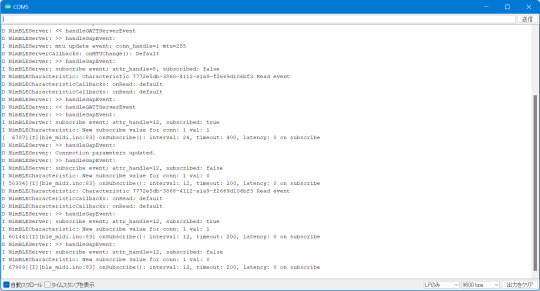
メインのコード(ble_midi.ino)では(テスト目的なので)USB MIDI関連のコードをコメントアウトし、代わりにシリアル通信でBLE関連のイベント発生時に接続パラメータを送信するように実装しています。これは、EPS32 Arduinoで用意されているlog_i()の関数を使っています。この関数を実行すると、USBシリアル通信経由で指定した値がログとして送信されます(この機能を利用する場合、Arduinoの設定でUSB Modeを「Hardware CDC and JTAG」に、「Core Debug Level」を「Info」以上に設定する必要があります)。
ちなみに、NimBLE-Arduinoはデフォルトでログ用のコードが実装されており、「Core Debug Level」の値に応じてUSBシリアルでデバッグ情報を送信してくれます。便利!
テスト結果
まず、接続パラメータの変更リクエストを送信しないケースでは、接続時の接続パラメータはIntervalが30ミリ秒(1.25ミリ秒×24)、Timeoutが720ミリ秒(10ミリ秒×72)、Latencyが0となっていました(Intervalの単位は1.25ミリ秒、Timeoutの単位は10ミリ秒なので、取得した値にそれぞれ1.25、10を掛けた値が実際の時間になります)。
[ 13624][I][ble_midi.ino:49] onConnect(): interval: 24, timeout: 72, latency: 0 on startup
その後、こちらからは接続パラメータの変更要求を出していないにも関わらず、接続パラメータの変更が行われました。変更後の値はIntervalが15ミリ秒(1.25ミリ秒×12)、Timeoutが2秒(10ミリ秒×200)、Latencyが0となっていました
D NimBLEServer: >> handleGapEvent: D NimBLEServer: Connection parameters updated. D NimBLEServer: >> handleGapEvent: I NimBLEServer: subscribe event; attr_handle=12, subscribed: false I NimBLECharacteristic: New subscribe value for conn: 1 val: 0 [ 20477][I][ble_midi.ino:83] onSubscribe(): interval: 12, timeout: 200, latency: 0 on subscribe
これはあくまで想像なのですが、BLE MIDIはリアルタイム性が求められるため、iOS側でBLE MIDIデバイスに対してはデフォルトでこの値を利用するように決められているのではないかと思います。
また、接続時に接���パラメータの変更リクエストを送信した場合についても同様に確認してみました(コード上でコメントアウトしている「pServer->updateConnParams(desc->conn_handle, 15, 15, 0, 400);」の部分が変更リクエストを送信するメソッド)。
まず、iOSのドキュメントで定められている接続パラメータに則った値で接続パラメータの変更リクエストを送信した場合ですが、この場合はそこで指定された値に接続パラメータがセットされました。たとえば「Interval Min=12, Interval Max=12, Timeout=400, latency=0」でリクエストした場合、次のような値に設定されています。
[ 23490][I][ble_midi.ino:80] onSubscribe(): interval: 12, timeout: 400, latency: 0 on subscribe
「Interval Min=48, Interval Max=72, Timeout=400, latency=0」のように、15ミリ秒より大きい値を指定した場合は、Interval Maxで指定した値が設定されました。
[ 17025][I][ble_midi.ino:81] onSubscribe(): interval: 72, timeout: 400, latency: 0 on subscribe
また、iOSのドキュメントで定められている接続パラメータに適合しない「Interval Min=6, Interval Max=8, Timeout=400, latency=0」という値を指定した際は、指定したIntervalには設定されず、代わりにIntervalとして24が使われました。
[ 27836][I][ble_midi.ino:80] onSubscribe(): interval: 24, timeout: 400, latency: 0 on subscribe
接続直後のIntervalの値が24(1.25×24ミリ秒=30ミリ秒)なので、これがiOSのデフォルト値で、適切でないIntervalが指定されるとこの値が使用されるように見えます。
結論
ということで、少なくともiOSでBLE MIDI機器を利用する場合、特に機器が接続パラメータの変更をリクエストしなくとも、15ミリ秒間隔で通信するように設定されるということが分かりました。つまり、前回テストした際もiOSでの最短Intervalである15ミリ秒間隔で通信が行われていたわけで、そこで発生した遅延は少なくとも接続設定変更では解決できないように思われます。
4 notes
·
View notes
Text
Arduino: Qué es y Cómo se Usa en la Electrónica y Programación
Baratos, eficientes y extremadamente poderosos. Conoce qué son los Arduinos y en qué se pueden utilizar.
Arduino es mucho más que una simple herramienta para hacer proyectos de “hágalo usted mismo”. Aunque es cierto que ha ganado popularidad en la comunidad DIY (Do It Yourself) debido a su bajo costo y facilidad de uso, su potencial va mucho más allá de simples proyectos de bricolaje. Esta plataforma de hardware libre está diseñada para ser accesible tanto para principiantes como para expertos, lo…
#arduino#Bar di Re Arduino#bootloader#bricolaje#diy#hardware libre#ide#inicios del arduino#ivrae#massimo banzi#mcu#microcontrolador#scada#utilidad de un arduino
0 notes
Text
Understanding ESP32 Pin Configuration: A Developer's Guide
The ESP32 microcontroller has become a cornerstone of IoT development, thanks to its versatility and powerful features. One of the most crucial aspects of working with ESP32 is understanding its pin configuration and capabilities. Let's dive into the essential aspects of ESP32 pins that every developer should know.

GPIO Pins Overview
The ESP32 boasts up to 34 GPIO (General Purpose Input/Output) pins, but not all are available for use in most development boards. Some key points about ESP32 pins:
GPIO 6-11: Reserved for internal SPI flash connection
GPIO 34-39: Input-only pins with no internal pull-up/pull-down resistors
ADC Capabilities: Two 12-bit SAR ADCs, supporting 18 measurement channels
Touch Sensors: Up to 10 capacitive touch GPIOs
Special Function Pins
Several pins serve dual purposes or have specific functions:
Boot Mode Pins GPIO 0: Bootloader mode when pulled low during reset GPIO 2: Connected to on-board LED in many development boards
UART Pins GPIO 1 (TX) and GPIO 3 (RX): Default UART0 communication Often used for flashing and debugging
SPI Pins VSPI: GPIO 5 (CS), 18 (CLK), 19 (MISO), 23 (MOSI) HSPI: GPIO 14 (CLK), 12 (MISO), 13 (MOSI), 15 (CS)
Best Practices for Pin Usage
Strapping Pins Always check the strapping pin status before using GPIO 0, 2, 4, 5, 12, and 15. These pins may affect boot behavior if incorrectly configured.
Input-Only Pins When designing sensor interfaces, prefer GPIO 34-39 for analog inputs as they're input-only and less susceptible to noise.
Pull-up/Pull-down Configuration
ADC Usage ADC1: Can be used with Wi-Fi/Bluetooth active ADC2: Only available when Wi-Fi/Bluetooth is disabled
Common Pitfalls to Avoid
Don't use GPIO 6-11 in your projects as they're connected to the internal SPI flash.
Avoid using strapping pins for critical functions that can't be changed during boot.
Remember that GPIO 34-39 don't have internal pull-up/pull-down resistors.
Be cautious with voltage levels - ESP32 pins operate at 3.3V.
Conclusion
Understanding ESP32 pinout is fundamental for successful project development. By following these guidelines and best practices, you can avoid common issues and make the most of your ESP32's capabilities. Remember to always consult the official ESP32 technical reference manual for detailed specifications and updates.
#ESP32 #PinConfiguration #DevelopersGuide #Microcontrollers #EmbeddedSystems #IoT #Programming #Hardware #Electronics #Arduino #ESP32S2 #ESP32C3 #ESP32C2 #ESP32C6 #ESP32S3 #ESP32H2 #ESP32P1
#ESP32#microcontroller#pinconfiguration#GPIO#ADC#DAC#I2C#SPI#UART#PWM#analog#digital#input#output#microcontrollers#embeddedsystems#IoT#InternetOfThings#electronics#hardware#software#programming#development#Arduino#ESP8266#RaspberryPi#microcontrollerprogramming#embeddedprogramming#IoTdevelopment#electronicdesign
1 note
·
View note
Text
10 years ago : Arduino open source projects
Open-source electronic prototyping platform enabling users to create interactive electronic objects. The Arduino platform lies somewhere between Technic Lego and the low level geek world of circuit building. It consists of two parts; the hardware and the software, and with these you can build almost anything, from a simple flashing light to a box of tricks that sends you a Twitter message…

View On WordPress
0 notes
Text
The Rise of Arduino Compatible Boards - An Exploration of the Expanding Ecosystem
The Genesis of an Open Source Movement When Arduino was launched in 2005, it helped spawn the age of accessible, affordable microcontroller boards and platforms. By providing a common hardware and software standard that was simple to use but still powerful, Arduino opened the door for non-engineers and electronic hobbyists to easily create interactive projects and prototypes. This drastically lowered the barrier to entry for physical computing and embedded systems. Within a few years, the Arduino platform had grown into a thriving global community with developers of all skill levels sharing code, tutorials, and ideas. The Growing Demand Inspires New Options As Arduino gained popularity and demand increased, companies recognized an opportunity to expand the ecosystem. Rather than competing directly with Arduino, many started releasing boards that were compatible with the Arduino software and libraries. These clones and derivatives allowed users to benefit from Arduino's openness while also having alternative hardware options at lower price points or with additional features. Some boards were nearly identical clones while others incorporated unique enhancements. Regardless, their compatibility with the Arduino IDE gave users the flexibility to choose a board that best fit their specific needs and budgets. A Proliferation of Board Types and Form Factors Today, the variety of Arduino Compatible boards available is staggering. In addition to the classic Uno and Nano form factors, there are boards shaped as mini PCs, single-board computers, wearables, educational kits, drones, robots, and more. Each brings something new while still maintaining the foundational principles that make Arduino great. For example, some focus on size and portability while others emphasize power, connectivity, or cost. Educational boards make learning to code more interactive and hands-on. Industrial boards enable Arduino to be used in professional contexts that require certifications or rigorous testing. A World of Enhancements Beyond the Original Spec Many Arduino compatible boards one-up the original Arduino specs by including features like WiFi, Bluetooth, GPS, high-speed microprocessors, more memory and flash storage, additional input/output pins, and specialized sensors. Some push processing power to the level of Raspberry Pi while shrinking the board size. Others add compatibility for new languages beyond just C/C++. Interfaces like Ethernet, USB, and add-on shields expand what these boards can interface with. Many also supply dev kits with components, sensors, motors and displays to simplify prototyping of specific project types. Get more insights on Arduino Compatible
Unlock More Insights—Explore the Report in the Language You Prefer
French
German
Italian
Russian
Japanese
Chinese
Korean
Portuguese
Vaagisha brings over three years of expertise as a content editor in the market research domain. Originally a creative writer, she discovered her passion for editing, combining her flair for writing with a meticulous eye for detail. Her ability to craft and refine compelling content makes her an invaluable asset in delivering polished and engaging write-ups.
(LinkedIn: https://www.linkedin.com/in/vaagisha-singh-8080b91)

#Arduino Compatible#Microcontroller#Open-Source Hardware#Electronics#Prototyping#DIY#Hobbyist#Maker#Microcontroller Board#Arduino Uno
0 notes
Text
1 note
·
View note
Text
Want to Learn the integration of Arduino with MATLAB? Read this Blog and understand the Basic Input/Output Commands for Arduino using MATLAB & Simulink. Now you can create a Simulink Model and configure the Arduino without even writing a single line of code.
0 notes
Text
Kursus Coding Software hardware di Mojokerto
Kampung Robot Mojokerto melayani kursus coding di Mojokerto, segala jenis bahasa pemrograman software, segala jenis pemrograman hardware, pembuatan proyek IOT. didukung kurikulum internasional dan kesempatan untuk mengikuti lomba skala internasional.Hubungi kami untuk informasi lebih lanjut. Dapatkan promo menarik untuk pendaftaran di awal bulan.Lokasi di The Suam Residence A-17 Kedungdung kota…

View On WordPress
#internet#koding mojokerto#kursus coding#les arduino#les c++#les coding#pemrograman hardware#pemrograman Web
0 notes
Text
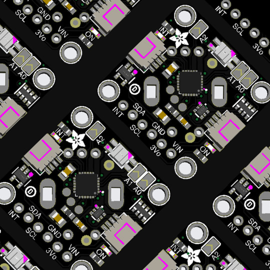
PCB of the day! Adafruit I2C Stemma QT Rotary Encoder Breakout with NeoPixel - STEMMA QT / Qwiic 🔧🔄🎛️
Rotary encoders are soooo much fun! Twist them this way, then twist them that way. Unlike potentiometers, they go all the way around and often have little detents for tactile feedback. But, if you've ever tried to add encoders to your project, you know they're a real challenge to use: timers, interrupts, debouncing…
This Stemma QT breakout makes all that frustration disappear - solder in any 'standard' PEC11-pinout rotary encoder with or without a push switch. The onboard microcontroller is programmed with our seesaw firmware and will track all pulses and pins for you and then save the incremental value for querying over I2C. Plug it in with a Stemma QT cable for instant rotary goodness with any microcontroller from an Arduino UNO up to a Raspberry Pi.
You can use our Arduino library to control and read data with any compatible microcontroller. We also have CircuitPython/Python code for use with computers or single-board Linux boards.
#adafruit#electronics#pcb#opensource#opensourcehardware#pcboftheday#arduino#raspberrypi#circuitpython#python#linux#rotaryencoder#stemmaqt#neopixel#i2c#breakoutboard#engineering#hardware#microcontroller#diy#technology
35 notes
·
View notes
Text
Wait actually I lied, more like
Internet Coder™: So first we need to install python
Internet Coder™: We're going to learn some low-level embedded techniques!
Internet Coder™: -heap allocates-
Internet Coder™: -uses OS call-
Internet Coder™: -uses stdlib string function-
Internet Coder™: -generally not careful with memory usage-
Internet Coder™: And that's how you write embedded code!
1 note
·
View note
Note
Are any of the toys Internet savvy? And would any of them get fooled by early scams and viruses, like the Pikachu email one?
DogDay is fooled by almost half of the early scams and viruses before he learns how to actually use a computer lmao, but Bubba, Delight, Long Legs and Kickin are all very internet/tech savvy. One of the mini huggies, nicknamed "Driver" by Angel but whose actual name was Pauline, is the ACTUAL go-to girlie when it comes to repairing tech. She loves it!!!! Prototype isn't internet savvy but he's very helpful with hardware. Kickin likes building computers, and I think Delight starts building little drones and learning arduino!
#poppy playtime#poppy worldwide#save everyone au#ask tag#dogday#bubba bubbaphant#miss delight#mommy long legs#kickinchicken#oc: driver
54 notes
·
View notes
Text
USB-BLE MIDIインターフェイスを作る - 環境構築編
1000円ちょっとでUSB-BLE MIDIインターフェイスを作ってみようという話です。
最近Bluetooth LE(BLE)を使って無線でMIDI信号をやり取りするのが流行ってますね。しかし、WindowsではBLE MIDIの対応があまりよろしくなく、Bluetoothが使えるPCでもBLE MIDIを使うのは難儀な感じです。ということで、いわゆるMIDI端子に接続して無線化するBLE MIDIインターフェイスを買うかな……と思っていたわけですが、そんな折ふとワイヤレスMIDI製品で知られるQUICCO SOUNDの通販サイトを見てみたらBluetooth MIDI基板なるものが。
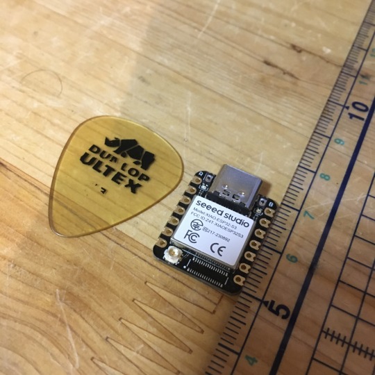
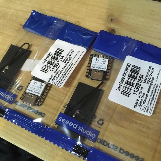
これ、小型IoTボードのSeeed Studio XIAOシリーズに似ているよなあ、XIAOシリーズはBLE対応しているし、USBポートも搭載されているからこれでUSB-BLE MIDIインターフェイスを作れるのでは? と思い立ち、早速秋葉原でボード2種類を買ってきました。
XIAOシリーズには複数の製品ラインアップがあるのですが、そのなかでも安いのが「ESP32C3」というモデル(税込940円)と、「ESP32S3」というモデルです(税込み1,150円)。
軽くネットで調べたところ、どちらも少なくとも公開されているBLE MIDIライブラリには対応しているようでした。また、USB MIDIに関しては、少なくともESP32S3についてはネットでUSB MIDIデバイス化させている記事(「蛇腹楽器型MIDIコントローラーV2 ~ USB MIDIデバイスの作り方」)がありました。
ということで、とりあえずESP32S3で試してみましょう。
開発環境を整備する
Seeed StudioのXIAOシリーズはArduino IDEで開発やプログラム書き込みが行えるのですが、そのためにはArduino IDEに追加のライブラリやボード情報をインストールする必要があります。設定方法はSeeed StudioのWebサイトに詳しく書かれているので、この手順通りボードマネージャURLの追加を行えばOKです。
USB MIDIやBLE MIDIに関しては、Arduino MIDI Libraryと組み合わせて利用できるライブラリが公開されており、これを導入することで簡単に利用できるようになるようです。いくつか選択肢もあるようですが、今回は次の3つを導入しました。いずれもArduino IDEのライブラリマネージャからインストール可能です。
Adafruit TinyUSB Library
Arduino BLE-MIDI Transport
NimBLE-Arduino
動作テスト用コードの実装
まずはこれで本当にUSB MIDIデバイスやBLE MIDIデバイスとして動作するのかを検証するため、MIDIのnote on/note offメッセージだけをやり取りするコードを書いてみます。前出の「蛇腹楽器型MIDIコントローラ���V2 ~ USB MIDIデバイスの作り方」や、「NimBLE + BLE MIDIで音を出した」、「M5StickC で、BLE-MIDI ドラム」などを参考に、こんな感じでコードを書いてみました。

やっている処理は
各インターフェイスの初期化
BLE MIDI側で受け取ったnote on/offメッセージをそのままUSB MIDI側に送信
USB MIDI側で受け取ったnote on/offメッセージをそのままBLE MIDI側に送信
の3つだけです。BLE MIDIの接続時にLEDを光らせる部分のコードはそのままコピペしたのですがコンパイルエラーになったのでとりあえずコメントアウトしています。
ビルドと書き込み
ボード設定はこんな感じです。
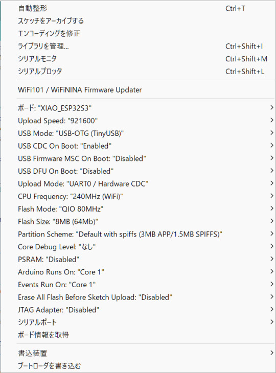
ボードとして「XIAO_ESP32S3」を選択し、それに加えてUSB Modeとして「USB-OTG (TinyUSB)」を選択しておく必要があります。また、色々とライブラリを使用しているためかArduino IDEがOutOfMemoryでフリーズしたので、前回記事で紹介したArduino IDEのメモリ設定の変更も行っています。
書き込み自体はボードをUSBでPCに接続し、シリアルポートを適切に選択して書き込みを実行するだけ行えます。念のため書き込み後はいったんUSBケーブルをポートから取り外して、再度USBポートに差し込んで再起動させています。
動かしてみる
BLE MIDI対応デバイスと言えばiPhoneやiPadですね。ということで、PC上のAbleton LiveからMIDI信号を送ってiPad上のGarageBandを鳴らしてみました。Ableton Liveからは問題なくUSBデバイスとして認識され、またiPadからも問題なくBLE MIDIデバイスとして認識されました。MIDIノートの送信もできています。
ただ、若干発音タイミングがヨレています。このあたりは改善したいところですが、果たしてできるのでしょうか?
(続く)
5 notes
·
View notes