#Small cone blender
Explore tagged Tumblr posts
Visit Tumblr Blog
Explore Tumblr blogs with no restrictions, modern design and the best experience.
Last Seen Tumblr Blogs


Fun Fact
After the announcement of the deal with Yahoo!, there were 170K signatures of unhappy Tumblr users petitioning to prevent the sale in 2013.
Text
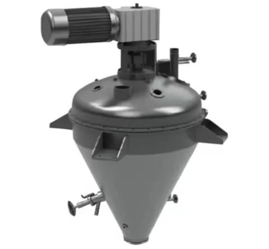
Double Cone Blender R&D Model

Double Cone Blender R&D lab model is a very efficient and versatile that is widely uses in laboratories. It is also known as small cone blender and that’s because it is pretty compact in size. One of the most popular blenders in the market, this machine is worth your investment.
Lab scale blender has a robust design and it is also known for its long service life. Due to its construction and features, it gives uninterrupted performance. If you are looking for a machine with fully integrated motors, advanced control systems and safety features, this machine deserves to be your pick. Owing to its two dimensional motion that works wonders and provides reproducible mixing results. There is a constant rhythmic pulsing motion that makes this machine a cut above the rest in terms of functionality and efficiency. Small cone blender is a highly efficient machine that requires minimal human intervention. It is ideally suited for small batch sizes.
Enterprises operational in various industries such as cosmetics, pharmaceutical, food and chemical industries choose this machine as it occupies less space and doesn’t demand more than routine maintenance. It also enables loose powder clumps to break easily which helps enhance consistency on all levels throughout the process. You can expect durability and less wear and tear throughout its service life. Besides, any necessary customizations can be made on demand.
0 notes
Text

Canary & Sons' Small Piano-Forte
Voilà! I am happy to present my own "square piano" for your historical sims to hone their piano skills!
In an age when domestic music making was usually accompanied by a lady at the harpsichord or Spinnet, the advent of the square piano was hugely significant. These compact pianos were designed and made by John Zumpe and sold from his house and workshop in Princes Street, at the north-east corner of Hanover Square. The oldest surviving examples are dated 1766. Many harpsichord players took to them immediately – their tone sounded so charming to ears that had known nothing but the harpsichord and organ – and these 'small Piano-fortes' were so inexpensive! Plain examples sold for as little as £18 – about half the cost of a single-manual harpsichord from Jacob Kirckman or Burkat Shudi (these being the two leading makers). For thirty years the harpsichord and piano-forte existed side by side, regarded as equally useful instruments, depending on what music you wished to play. Consequently, in many homes, in London or in Paris, you might find both instruments, often in the same room, their owners deciding that a 'small Piano-forte' could be readily accommodated. It would take up little space, and when closed it looked much like a side table. (source)

Following manymany tutorials, I have decided on my finished product.
It is a fully closed square piano, with loads of deco slots on it, so you can clutter up the place, while still managing to practice your playing.
I decided on just two wood shades, and for variety, there's 9 different stool cushion covers.


There's so many different designs of square pianos. Some have pedals, some don't - some have levers, and dampeners.... There'd be parts of the top which open - so that you can see the strings, and tune when needed (or to increase the volume). From 1768 onwards, three levers were installed in that small space to the left of the keyboard - so this would open up as well, in order to access these.
I had to decide how much I wanted - do I want it open at all? If so, both sections? I am not really very good at making things in blender, so it worked out better for me to do it closed up.
I also decided to keep pedals: though I don't recall seeing an animation where the sim presses the pedals, the game has cones here for pressing, so it's definitely possible!
I worked supersuper hard on this, so I really hope you all like it!
Download now, for free, via Curseforge!

~~ Terms Of Use ~~
#The Sims 4#TS4#the sims community#simblr#my cc#small piano-forte#square piano#Victorian#Georgian#activities & skills#piano skill#piano#historic cc#historicalcc#historical cc#historiccc#The Sims 4 custom content#TS4 custom content#The Sims 4 cc#TS4 cc#Canary#Canary & Sons#regency
89 notes
·
View notes
Text

blender lighting tutorial + tips.
requested by @thecrimsonsimmer + recommended viewing: youtube video one, two, three, and four. this post will be dealing with newer versions of blender (2.8+) and cycles since that's what i'm more familiar with + commonly used for rendering. this is coming from me as an artist with some dabbling in photography and things i've learned in college!
references and setting the mood
are you basing your render on an existing photo? study the light source and what direction it's coming from: that's what's going to tell you your set up for a similar effect. if you're not basing it on an existing piece, a good start is knowing How you want to set your subject (your sim) up - do you want them to be in the spotlight? are they in a specific environment that has neon lights? are you going for moody or something fresh, bright? definitely look up colors and their meaning (color theory, movie screencaps, etc.) to create a stronger image!

using resources to start the set up
it's always a good thing to mix your tools with different communities, such as the art community! many have lighting tools to figure out how to color their subject, such as this free-to-use head figure that depicts where the lighting source should be placed.

there's also the photography community and teaching people how to set up their lights for certain setups. video three and four linked in the beginning are from photography viewpoints.
spot? area? point? sun?
let's think of the lighting types as objects - a spot is like a plain lightbulb, area is a reflective sheet, spot is a flashlight, and the sun... well is the sun!
a spot is similar to an area light, but triangular/a cone. think of a helicopter search light, it's focused on a small area with the most light concentration. these can be used for lamps with lampshades, car headlights, or a lighthouse.
an area light is great for lighting up technology. a phone screen, tv screen, tablet, anything that's an LED screen emitting from a surface. the light is not as concentrated as a spot and is meant to cover more flatly (hence the rectangular source)
a point is best used for small pops of colors such as candlelight, lamppost, lightning bug tail, etc. a small source that has nothing covering it.
a sun covers the entire area and can be used as the overall mood setter. it can create filter over the entire render by just shifting the color like you would see in a movie. you'll be given a line with a sun light that gives the direction of where the sun is coming from. basically a spot light just on a much larger scale LOL.
power + coloring

this screenshot is mostly what you'll only use to start off with. watts is the unit of measurement and the higher you go, the brighter the light will be. examples with a white colored point light 10W-20W: general portrait lighting 30W-50W: bright source, close flashlight for example 60W+: blinding
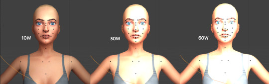
coloring is just like the system for in game lights for ts4. shift it to whatever you want it to be (click the white bar, that's the color preview) and mess around with the vibrancy. the darker, more intense color, the less it's going to appear on the sim.

closeness and intensity
similar to what's shown in the head lighting tool shown earlier, the closer the light is, the more that specific area is lit up. go too close and your sim could be completely washed out. it helps to change the size of the light (change with the radius slider) to better imitate what you're wanting. the larger the radius, the more diffused and softer the light source will be. close + small = very clear of the light source shape, can obviously tell where it is in relation to the subject far away + large = soft lighting, more of a hazy lighting of the color you choose.


to quickly adjust the light, press "G" and hold down your middle mouse button to adjust which axis you'd like to edit along. green is the x-axis, blue is the y-axis, and red is the z-axis. you can also press "G" and type the letter of the axis you want to use. drag the mouse to change the placement on that specific axis to however you want. if you want to freely edit the placement, just press "G" to move it out of the axis bounds.
world lighting
take this step as setting your canvas color before you start painting. in order for the values to look their best, change the world color to the same hue of the color you are mostly using. for example, this is set in a red-toned environment:


this is essentially changing the cast shadow onto the sim. the default is gray and will muddy up your undertones if not changed properly. for this instance, if you were to still use the same red point light in a gray world color it'd look like this:

of course, this will be based on if you have an environment image or not that can affect your lighting overall. this post is based on the fact there is no environment image and what not! if you need a visual demonstration on how to mess with the world lighting, check out this short video.

i hope that helped anyone beginning to render or wanting to light up your own scenes! i'm no rendering expert, but here's some of the helpful tricks i've learned and collected over the years<3 if you have any other questions feel free to send an ask!
#ts4 blender tutorial#sims 4 blender tutorial#ts4 render tutorial#sims 4 render tutorial#lighting tutorial#lyko posts#tutorial#long post
244 notes
·
View notes
Text
Maybe Next Time He'll Think Before He Cheats, The Cousin Duet[ GENEVIEVE & DENISE ]

[ ID: Traditional art mostly done with sketches and with pencil in places. It has an old paper tetxure to it. Its a piece in the early, stick figure like, Dork Diaries style of the OCs, cousins Genevieve and Denise, from user Jack_iscool at Artfight 2024.
Genevieve is a thin girl with curly hair. She has on mascara and hoop earrings. She wears a tee shirt that says 'Angel' in big letters, with a halo and wings added. She wears jeans as well. Around one of her wrists is a hairband and a ribbon, and the other has a bracelet.
Denise is a thin girl with medium length hair in bangs. She has on sunglasses and a heart necklace, she also wears a really big sweater-coat with flower decorations. It's topped off with a denim skirt.
Genevieve grasps a melting ice-cream cone, using it as a microphone to sing at the top of her lungs. Mascara runs down her face as her face twists in passionate fury. Her other hand is folded, pointing upwards into a fist. She stands in a stance thats leaning forward. Denise holds a pair of wilting roses, the petals ripping away, throwing her head back and grinning as she belts out the duet. Her other hand is held out, curled and her feet are wide apart. They are both lined in black sharpie.
A fire rages in the background, lined with red, orange and yellow sketch. There are a bunch of objects on the floor, lined only in pencil. They consist of: torn photographs( one with a lipstick mark on it), a blender with a salad dish disconnected from it's plug, a tub of opened ice-cream, a tissue box with a decoration of broken hearts, rolled up tissues, a camera, a slashed heart shaped box with ribbons revealing a knife inside, and finally a trashbin with a small teddybear and a bouquet inside. All signs of a messy heartbreak. End ID]
--
Artfight 2024 attack for Jack_iscool of their OCs Denise and Genevieve!
--
My last Artfight attack of this year ;w;
I drew these gals in the dork diaries style, because they had that nostalgic feeling around them
Very fun piece to do!!! Ended this fight with passion!!!
The title is a reference to the Carrie Underwood song!!!
#my art#dork diaries#Genevieve#denise#before he cheats#carrie underwood#music#breakup#heartbreak#nostalgia#diary#Jack_iscool#artfight#artfight 2024
3 notes
·
View notes
Text
oh boy we're a little behind schedule again
for clarifying purposes (including image descriptions), all images are of animals constructed of simple deformed polygons made using Blender modeling software. The background is a grey grid with each square having a side of 1 meter in length. These are all rough models of examples in clades during the global glaciation event and during the warm period following the glaciation. While these body plans are all in use during the period following the glaciation, some have been used for over 150 million years.
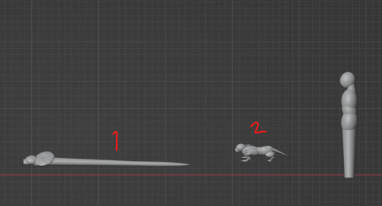
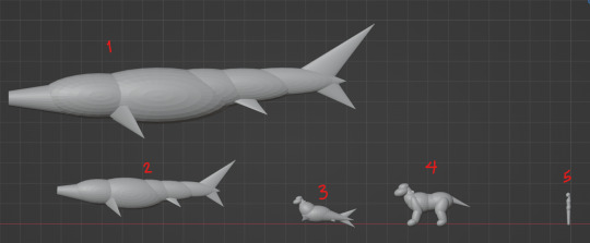
[Image ID: Animal 1 is a snake roughly 2.5 meters long with a ring like mane of hair that sits just past the head. Animal 2 is meant to resemble a thin armadillo and is roughly 0.5 meters across. Animal 2 has two long patches of hair extending backwards from either side of the neck. ./end ID] 1- Graminovoris Coclemanus Vibratis Cristavermis is a radiated variety of animal 2 which has evolved to not use limbs. This clade boasts one singular ear which funnels sound down through a collapsable disk of hairs into the tympanic cavity. This clade has evolved a new method of sexual copulation which resembles that of the Dactylatusids. 2- Graminovoris Coclemanus Vibratis survived the ice age due to small size, high metabolism, and propensity for burrowing. This clade has no ears, but can hear rough pitches and volumes with the hyper sensitive cones of hairs protruding from its gametangium cavities.
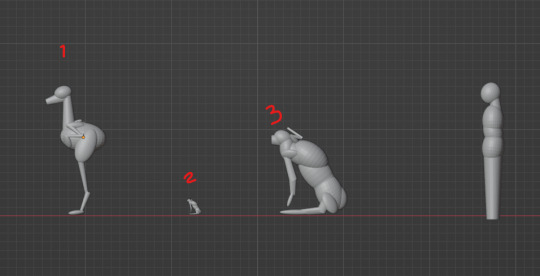
[Image ID: Animal 1 resembles a emu in posture and shape, is 1.5 meters tall, and has no tail. Animal 2 is difficult to make out due to it being so small, however it is identical to animal 3 which is more easy to see due to size. Animal 3 is 1 meter tall, and resembles a cat with long limbs, however it lacks a tail. Animal 3 has a large protrusion on its back. Between this protrusion and the head there is a set of small limbs resembling the praying hands of a praying mantis, with the ends angled in the direction of Animal 3's gaze. ./end ID] 1- Generatheris erectus is an offshoot of the ancient generatheris clade. This newer clade has developed tympanic ears located within cavities near the base of their uppermost set of limbs. It has evolved to both evade predators and to catch flying insects or vertebrates. 2- Generatheris Vesicahastas telaplexus has taken up the niches typically associated with silk producing spiders. 3- Generatheris Vesicahastas boasts many different varieties of vesicahasta which almost ubiquitously weaponize their upper limbs to spray acids, webs, or foul smells. These two models are both lacking the sensitive stiff fans seen in other generatherids (because I forgot).
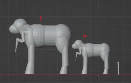
[Image ID: Animal 1 loosely resembles an elephant 7 meters tall and 8 meters long. Animal 1 has no trunk or tusks, instead boasting an additional set of limbs extending above the front shoulders towards the head, in a position which resemble the praying hands of a praying mantis. Animal 2 is identical except that it is 5 meters wide and 4 meters tall. ./end ID] 1 and 2- Barritherium Borealis, both of these variants have seen very little change, much like generatheris. These animals do not have fur, but have thick coverings of feathering quills. modern barritheriums are predominantly marsupial but some still lay eggs. These animals have stiff fan disks which channel sound down into tympanic cavities. Many species use their gametangium limbs as clubs to fend off predators preying on young barritheriums.
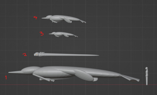
[image ID: Animal 1 resembles a long fish roughly 18 meters across by 6 meters tall when counting fins. Animal 2 is the same as Animal 1 except scaled so that it is roughly 9 by 3 meters. Animal 3 resembles a seal with a vertical tail and is roughly 3 meters long and 2 meters tall. Animal 4 resembles a hippopotamus with a long tail, and is 4 meters long by 2 meters tall. Animal 5 is a roughly 150 centimeter tall person. ./end ID] 1 and 2- Dactylatus gramisugus terrapescus cetaceaformis, the newest megafauna within the planet's oceans. As Dactylatusids, they have complex ears, warm blood, and fur. Their tail fins are almost entirely made of fanning cartilage spurs. 3- Dactylatus gramisugus terrapescus is basically a seal. Their fins are oriented vertically and made of cartilage. 4- Dactylatus Gramisugus is a hippopotamus. Nothing else to say there.
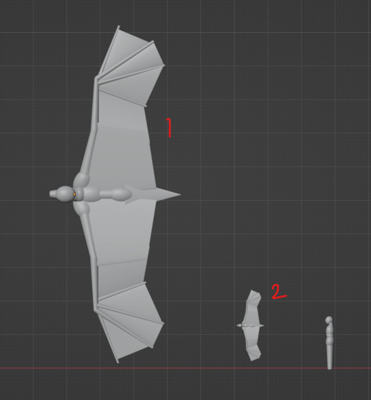
[image ID: Animal 1 is almost identical to a bat, however it has a wingspan of roughly 10 meters, body of 4 meters and is turned to resemble a top down view of a bat with splayed wings. Animal 2 is a scaled version of Animal 1, such that the wingspan is 2 meters and body is approximately half a meter. ./end ID] 1 and 2- graminovoris Mustelidiform latusala pteromanus are the first ever flying vertebrates on Meldonis! They are free to occupy all the niches that flying birds occupy today, as well as the ones large pterosaurs (and associated archosaurs) occupied, due to a denser atmosphere. Thankfully their ancestral designs were well adapted to efficient flight.
[Image ID: Animal 1 resembles a crocodile in shape, however has 2 horizontal hind flippers at the end of the body, 2 vertical flippers on the bottom and midway through the body, and has 2 front limbs resembling the praying arms of a praying mantis which are clutched to the chest. This animal is 12 meters long and roughly 1 meter tall. Animal 2 is a snake 6 meters long, and has similar limbs to Animal 1, however these limbs are held towards the top of the snake's body. Animal 3 and Animal 4 are identical to Animal 1 but scaled to 3 meters long and 4 meters long respectively. ./end ID] 1, 3, and 4- Manipescus ripatherium Hastajectarius occupy similar roles as crocodiles and aligators. These animals lay hidden in wait at riverbanks or crossings, and when prey comes within reach lash out their scythe-like arms, shredding and ensnaring their targets before dragging prey into the water to be finished off. 2- Manipescus ripatherium hastajectarius vermiformis is another independent clade of snakes who wait in burrows and primarily ambush small prey with their scythe-like arms.
5 notes
·
View notes
Text
How do I make incense cones with flowers?
Making incense cones with flowers is such a relaxing and fun DIY project—and it smells amazing too! Here's a simple way to do it naturally at home:
🌸✨ DIY Floral Incense Cones
🔮 What You’ll Need
Dried flower petals (rose, lavender, jasmine, marigold—whatever you like)
Makko powder (natural binder made from tree bark; helps it burn) OR tragacanth gum, guar gum, or even just water and cornstarch if you’re improvising
Herbs or spices (optional): sandalwood, cinnamon, sage, etc.
Essential oil (matching your flower scent, like rose EO for rose petals)
Water (for mixing)
A small mixing bowl, spoon, and parchment paper
🌀 Step-by-Step Guide
1. Grind the Petals
Use a mortar and pestle or blender to crush dried petals into a fine powder.
You can mix with powdered herbs if you want (like sandalwood for a woody base).
2. Make the Base Mix
Combine:
2 parts ground petals
1 part makko powder (acts like incense glue and helps it burn evenly)
A few drops of essential oil
Add a tiny bit of water slowly, just enough to make a clay-like dough.
3. Shape the Cones
Pinch off small bits and roll into cones with your fingers.
Make them about 1 inch tall and flat on the bottom.
You can also shape them like little pyramids or spirals if you’re feeling artsy!
4. Dry the Cones
Set them on parchment paper or foil.
Let them air dry for 3–5 days in a cool, dry place (flip them after a day or two so they dry evenly).
Make sure they’re fully dry before burning—if not, they won’t stay lit.
🕯️ To Use
Light the tip, let it flame for a few seconds, then gently blow it out.
Place on a heat-safe dish and enjoy your handmade floral vibes 🌸
Want help picking a flower blend for a certain mood (calm, energy, focus, etc.)? Or want to turn these into a gift set?
0 notes
Text
Blender donut
I've picked up a lot of useful tasks from this tutorial I watched. Here's a breakdown of what I've learned so far:
Navigating the Interface: I got comfortable with Blender’s interface, figuring out how to move around in the 3D viewport, select and manipulate objects, and use the toolbar. It took a little time, but I feel pretty confident now.
Creating Basic Shapes: I learned how to add primitive shapes like cubes, spheres, and cones to my scene. From there, I practiced scaling, rotating, and moving these objects to position them just right.
Mesh Editing: One big thing I picked up was using tools like extrude and loop cuts to add detail to my models. I also started using the Subdivision Surface modifier to smooth things out and make them look cleaner.
Modifiers and Sculpting: I played around with modifiers like Mirror, Subdivision Surface, and Boolean to make the process more efficient. I even dove into sculpting a bit, learning how to use different brushes and dynamic topology for more detailed work.
Texturing and Shading: I practiced UV mapping to unwrap my models and apply textures. Also, I got into the Shader Editor to make materials and shaders. The node system took a little time to get used to, but it’s a really powerful tool for creating cool effects.
Lighting and Rendering: I learned how to set up different lights in the scene to make it look more realistic. I also played with the rendering settings, switching between Eevee and Cycles, and tweaking them for the best results.
Animation Basics: I started animating by setting keyframes for objects. I even explored the Graph Editor to get the timing and movements just right.
Finalizing the Scene: I figured out how to set up the camera to get the perfect shot of my scene. Finally, I learned how to export my models in formats like .FBX, .OBJ, and .STL.

To add icing to my donut model in Blender, I started by selecting the top face of the donut where I wanted the icing to go. I switched to edit mode and used face select to pick the top face of the donut. Then, I pressed E to extrude and started pulling the icing up from the donut's surface. As I extruded, I moved the new geometry slightly upwards and outwards, making sure the icing flowed over the edges. I used S to scale the icing and give it a nice, smooth, flowing look around the donut. After extruding, I smoothed out the icing shape by tweaking the vertices and adding some small adjustments, making it look like the icing was naturally draped over the donut. Finally, I exited edit mode to see the whole result, and it looked just like a donut with a perfect layer of icing on top
I also learnt how to make object smooth. As you can see the icing of tis donut was very pointy and not realistic. Therefore, I learnt from this to do that I have to be on edit mode to click on each dots then play around to see what looks best.


I managed to make the icing and I am proud of how well I did this for first time.
However after making the icing drip I realized the top bit got messed up. probably because the dots were pulled down too much.
0 notes
Text
Filament for 3d printing standard piston engine stuff
Blend nylon, polycarbonate, polyester, weather proof cable (pretty sure it is Polyphenylene sulfide & or thermoplastic polyamide) & trash can polypropylene. Blend in only glass blender that is strong but cheap & has blades that are very sharp but typically like to smash things in the side walls of the blender.
From there is has to be mixed together in another "blender" it's not grinder or blender though. Its a "sand blaster blender" 2 or 3 inputs of a sandblaster full of the ceramic, metal, & the plastics in an argon environment that sucks the polymers together with the metal back in & then accelerates (fires) them into each other at high velocity. Everything must be dry, extremely dry & grounded. Or made to be positively charged in the cone shaped vacuum separator like design. So saw dust vacuum separator will work for this & it's metal. But they can be expensive, it depends on what you want to do & make, me & others.
After rock polishing with large (semi I guess) medium & very small hardened steel ball bearings, make sure I get (or anyone else) micron sized nickel, selenium, zirconium, molybdenum, & silicon
Also these ceramics need to be bought & rock polished. These are all high strength & hardness ceramics that are sucky to deal with. But "polishing" them just means breaking off tiny small chunks to get them fairly uniform & to make them slightly charged. But it must be done at then end because you are, very likely, going to ruin your rock polisher if you didn't electroless boron nitride coat/plate them.
Caswell Inc is a great place to buy the playing kit for boron nitride. They even have an app for your phone.
Boron carbide, zirconia- alumina, silicon carbide. Cubic boron nitride can help as well.
During the "blending stage" (hopefully you played the inside of the cone drum thing otherwise this will absolutely destroy it & wear it away hard) you are going to make sure to go to smaller & smaller sizes of the cone & faster & faster speeds of travel for the plastics, metals, and ceramics. If you started out with a very large vacuum saw dust separator it will be harder from here but you can place smaller ones inside. This means it can act as a cascade onion "blender" all in one. Which is cool!
But most of us can't do that... So instead it's fine to start small & just go with a cut up big plastic trash can then work your way down, for what it is worth.
From here it's melting everything with the right ratios. Depending on what you want your ratios will massively change results. This is for the whole engine block & case & head. Like a small single cylinder 4 stroke that's maybe no more than a 125cc. I recommend just sticking to 75cc to make it easier to print everything.
The plastics are even blend, so that means equal parts & there are 5 total so 20% for each. Nothing fancy there.
The metals are different, so harder sadly. You want mostly nickel, you will never go above 89% for the metal ratios. So to make it easy, 75% is a great starting point. That leaves only 25% left for 2 other metals, 1 metaloid, & a non-metal. Zirconium & molybdenum are annoying, seriously & they tend to be expensive! So this means they have the greatest total out of that 25%! *Sarcastic* yay! You can get away with less in other areas but it's hard to blend that all in one spool & soooo...nah. make multiple but honestly who had the time for all this so it's probably easier to just blend it all together for one run.
Split zirconium as a 15% & molybdenum as a 5% which is a lot. Subtract 20 from 25 & you get 5% left over. Although that's because the ceramics & plastics are going to bond chemically with these metals to make this work together, later. Whole thing.
So 5% left now. Selenium & silicon, silicon is 1.5%, yes a harder number to work with by gram weight, but doable. The rest is selenium. 3.5% of selenium added in by weight.
Next are ceramics. Ceramics are annoying as well, sadly. These bastards have no even numbers! For their ratios to each other at all! So be prepared, just saying. Which we will get to the ratios of metal powder (that is already ratio'd as a total whole weight) & the plastics (that are already ratio'd as a total whole weight) later for the 3 coming together in the final ratio needed. Ceramics first.
3 ceramics or if you want 4, but boron is in 2 & so it has to be changed for that blend as there is already silicon & zirconium in the metal blend. Which makes it tougher to do this. The zirconia-alumina (yes if you Google high strength & hardness ceramics you get these, just so happens they work well together for this application & really I like the coincidence honestly) is a semi-majority. Its 40.3362% by weight.....
Yup.
Its actually super important to go 4 decimals. So large weight is needed to make it easier on everything. Who the hell is measuring nanograms, not me. Or micrograms for that matter. Milligrams are hard too, but actually doable with relatively cheap scales you can buy on Amazon even. But f those other snaller grams. Nope, not doing it.
Boron carbide is 5.0522% and silicon carbide takes up the rest. Which is 100% - 45.3884% & that works out to 54.6116% of silicon carbide.
Now, if you want to use some cubic boron nitride you can put together a ratio like this to start off with instead. Zirconia-alumina is 32.5632% boron carbide & cubic boron nitride works to 25.4363% & the rest is silicon carbide, so 42.0005%.
Which....kinda sucks. But larger weight totals make it much, much! Easier.
Now the ratios of the plastic, metal, & ceramics combined. They are not easy non-decimal numbers. So, doing that again. Plastic is 40.2361% the metals are 26.1212% the rest is ceramics for a 33.6427% by weight.
The majority is still plastics, polymers. Ish. Kinda, not really. Most is metal & ceramics. But it needs to be heated together & squeezed & extruded through a nozzle to make a filament.
So, sandblasters have a tungsten carbide nozzle that you can electroless boron nitride plate. Which works. But diamond would be better, however who had the money. Geez. There are 1.75mm opening coolant holes tungsten carbide rods that you can buy that are straight pass through rods, somewhat expensive but not terrible.
Playing them is also not terrible. It makes it last significantly longer. You must keep a very, very consistent ratio throughout this & it likes to separate easily, which is the worst. So no vibration feeding or auger feeding can be done. There needs to be a cone that feeds to the rodz funnels are great. If you could find one the right size.
So instead this is the best & only way to actually do this, but it's a "suck it up and just do it stop complaining to yourself" way. You need to evenly spread this out with a non-separated ratio of everything & squish it with a lot of heat. Like with a T-shirt logo press. Or with something quite similar to this. One plate is not done. Not above 500c & not below 380c! This will destroy bonds and or not adhere. The pressure is at least 100 psi no more than 500psi. The higher you go the worse performing it gets past a point but depending on how dry it is, if you got ratios right if you had more static that day even to if you mold released or not all of it will change total pressure. Practice, but remember I & we don't need it perfect I have stuff below to help remove this inaccuracy & inconsistency to make sure it is good at the end.
Make several, you aren't perfect so it won't be perfectly blended. Its okay I have a way around that. Get a heated roller. Think making pasta & the rollers are heated. That's what that is. Which means you can get your stainless steel pasta roller & electrically resistively heat it after ceramic coating it to make sure it doesn't zap you & you are good to go! 👍
From here you squeeze the plates to a thinner plate, 3mm if you can do it. 1mm is great too. No more than 5mm because they suck to break and snap apart which is what I & anyone else following along needs to do. Get out a soldering iron, yup. You need a SOLDERING IRON!!!
So after you get that out you will "score" a grove into the new sheet you just created & "break it" apart after letting it cool. DO THIS IN A WELL VENTILATED ROOM & OR OUTSIDE!!!! Please, your lungs will die sooner than you wanted & replacements are hard to find. Make sure to use respirators (air filters strapped to your face) & gloves (nitrile works) & a fume hood with a great air filter for the off gassing that occurs. Activated charcoal (carbon) with a great particle filter filter, meaning two different filters. A percolation setup as a pre-filter stage works too, water is fine as long as it is distilled & deionized. Percolation means your (sticky icky) favorite past time filter. Lol, or just anything that allows for a tube to go underwater & have air sucked through & it bubbles up through it. No worries ☺️.
Now after you make sure you have those, you cut the sheets into strips after breaking them after they cool & or heat cut them. From there you will roll them in a vacuum in the long ways fashion, make sure your strips are wide enough to do this! Then flatten them in the roller in the vacuum.
Amazon doesn't have vacuum boxes big enough! So instead I & you can make a vacuum pump do work for us. A sandblaster cabinet can be modified to have structural corners added with light epoxy & or welding done. I recommend welding with a basic spot welder because you only need a plate steel that is 3-5mm thick at corner angles & arches from those to the longer flat sections.
Think a round box inside the box. This allows for the flat parts of the sheet steel to be supported by the plates & the corners so when it tries to collapse it actually pushes against the pressure & uses stronger material to accomplish this. Bolting them in after drilling them epoxying them down is another great way to get this accomplished if you don't know how to weld. It work just as well too!
After you made your huge vacuum chamber that has little arm holes already in it with the gloves provided that can handle abrasion & heat & all that already, because sandblaster cabinet, remember that pressure is different & wants to work it's way into it.
So, you need to significantly epoxy & or bolt more bolts down on your gloves to seal them & prevent vacuum leaks. The gloves are likely thick enough to not burst if they are halfway decent. If not fiberglass & or kevlar can work as a fabric you place over the gloves to make sure they won't break. You just need to bolt down the fabric to the cabinet where the gloves are bolted in & sealed too.
After you make you vacuum cabinet. Steps above. You can now roll the polymer "rug" strips flat & then fold them & proceed again. Vacuums don't have convection cooling. So flatten & fold. Then on to the next one. Do this to all of them first, which is why I had you read that you can make multiple together at once.
The heat of the roller needs to never be above 500c & below 380c! This is extremely important! It destroys bonds & makes it likely that much of it won't adhere together later. Crumbles suck! Remember the psi problem too.
Keep the vacuum pump vacuum pumping. This gets rid of volatiles & off gassing that can contaminate the polymers & or metals/ceramics.
After you complete all strips to folded (just once in half is fine) semi-sheet/plate things you move on to letting it cool off in argon.
Argon gas, yes.
From here it's so it again with another fold then roll it to very long strips again.
Repeat cooling argon recirculation pump. Pump argon out & compress it into tank. Use compressed argon again, you use vacuum pump for off gassing & volatiles separate, filter them if you can.
Then vacuum pump it, get the strips turned into a nice braid after rolling them thinner & then rolling them sideways long ways to turn them into more fiber while they are still warm. Upon braiding you will roll those all together flat one way then twist that then roll it flat again.
Then from there you need to cool them, so, another cooling stage.
Then vacuum then fold the sheet & roll it & then fold the sheet again & roll it again.
Its done, ish. From here it's needing to be chopped up & it will finally be able to go through extrusion.
Yes. I know. This has been a lot of work... Its worth it though.
From here the chopping up is similar to stripping but all done in the argon cabinet. So it doesn't oxidize, mostly & it remains very cool as argon is a much better thermal conductor than regular air! Yay!
The hot plate you used to squish this would be useful to have in there already. But if not get it. You are going to roll these stupid things into pellets that you can actually use with it, unless you have another method in which case use that. I use a tube roller, it's the rollers but I have a tapered tube on the inside that has grooves in it like a cartoon tunnel drill for villains. Funny, but actually totally usable. I metal 3d printed it using a online website (pcbway, xometry, jlcp, etc etc all work) you don't need it to have grooves I just wanted it to be highly specific in sized & shape at the end.
I also plated it. Nickel (it's stainless steel) plated then nickel boron nitride from Caswell Inc.
You can just get away with a stainless steel funnel you can buy at a store for cooking & it will 100% work! It just needs to have no holes in it. Less argon & a little more heat will do the trick.the pellets come out as little round balls & that's how you know they are done. Personally I recommend no argon in a vacuum so there are no argon pockets of air, but it's okay if they are there in very small quantities & sizes.
If not then you can then vacuum it out & just reheat everything & roll them through again (in the tube) & have it be a slightly smaller size to remove all argon gas pockets & have them come out as little pellets again, woohoo! If you use the plate you just need another plate & you'll rotate the plate around in a circular fashion until you get little pellet balls. Works the same just somewhat more work, you need a separate sheet & or plate for the heated surface below. That's all.
Now from here the sandblaster nozzle & or tungsten carbide rods with a 1.75mm coolant hole will be used. You will need to heat them, typically that means a iron-ceramic (the same in electric stove top coils) heating element & a thermal probe in-between with a little boron nitride thermal paste to tie it all together. This lets you know what you need to know for heat. But! We have to feed pellets into the hole & with need a connector funnel.
Soooo.....
Here's where a lot of things become based on what you want to do & so on. If you have a Dremel (rotary tool) you can use just about any diamond cone shaped but to enlarge one side of the road or sand blaster nozzle. Diamond is harder that tungsten carbide. So it will do it. To fit it a press fit is easiest to do. That means another rod with a 2mm coolant hole is best, but they are massive so you will need to funnel down that other rods (or nozzle) tip that will press fit into that & seal with thermal paste (boron nitride) yes that part is actually necessary. The pressures during extrusion get higher & there is a lot of very small fine particles that will fit through your not perfectly sized holes. Be realistic with yourselves like me & so you will do it good but not perfect...
To feed this in, the pellets, a piston driven heating tube is the only way to do this. Yes, that is right. So an electric motor driving a crank (any piston compressor for ac components will work) is the only way to do this. But you have to rotary tool out the side & 2 stroke it with pellets. You have to drill out, or rotary tool out, the sidewalks near the cylinder (leave 5-10mm of material in-between the cylinder side walls) & place in heating elements (rods that heat up work just fine) but make sure you plate the cylinder side walls with boron nitride to increase the lubricity of the whole thing as well as the piston heads skirts (sides of the puck) with it too. The extrusion has to be at a minimal 35-42 degrees facing downwards to limit oil from the crank getting into the cylinder. I used no oil at all. I just turned it off & let it cool down. I first cleaned the shit out of it with isopropyl alcoholic & degreaser.
I left a thick grease for wheel bearings on the bearing for the crank & piston connection rod. So it would unlikely move into the cylinder.
I do think it will effect the end result of oil gets in. So...I dunno be careful.
Now, I did this all still in the vacuum chamber. Because it was easier than removing everything & I was tired & didn't want to. Soooo... again it might be worth it to just have everything stuff in there & say bah to removing it until it's done.
During the extrusion process the heat for everything is very, EXTREMELY, finely controlled & monitored. The piston is 410c let it warm up everything inside the cylinder, including the plastic, the piston head, & the head that I didn't describe.
Silly me. So the head is modified in a shape that press fits the other rod/nozzle directly into it. Which meant, a hole saw/drill thing & the rotary tool for fine adjustment & sand paper at the end to really make sure. Press fit is a rubber mallet & some cloth because tungsten carbide is extremely hard & can cut through that aluminum like it's not even there. Be careful please. A healthy gasket material on the sides & making sure to fully remove camshaft & making sure the valves remain stuck while also grinding down smooth the valves to be completely as flush as you can to the head is needed, just as much as the inside of the head to taper it to the other rod. The smaller the piston the easier this gets.
Right, back to the temperatures needed. 410c for the piston pump is the best temp to start off with, slow but high torque is best for this.
The next rod/nozzle that is the 2mm coolant hole or sized one is going to be much hotter, 550c the entire way. The heat bleed is crap, so a copper capillary tube is the right call. You just need to drill a hole through the cabinet & seal it with epoxy & run it to a computer radiator & use a computer pump. Works just fine the return line is just a copper tube that goes to the capillary tube at the press fit juncture.
But to make it, likely, much easy on you & I (although I figured quick disconnects with a metal hose clamp would work & so that's the working thing going on moving forward) you could just thermal epoxy & copper tube it up! It works pretty well, as well. You are going to need thermal paste g or epoxy anyways to adhere it to the juncture & transfer heat but still *shrugs* most don't want to solder I get it & this will work from a smaller tube to a larger tube all the same.
From here it's cooling it down only to 485c & keeping that going all the way to where it comes out.
From there a filament holder roll is your best friend. You have to be very careful to not lose heat during the process of rolling it & turning it, so a ir heater works just fine for this. 👍 😁
From here after all pellets are processed & you are fine with the small amount left in the piston pump, you are done. Turn off the ir space heater & let it slowly cool off in the vacuum while you sleep & come back to it after a week because it takes forever for things to cool in a vacuum.
If it's cooled before that, it's okay. But there is a final step to this that has to be done. Anealment. Yeah so in the argon you are going to heat it up to 220c & have it come back down to 15c, roughly, over the course of 3, OMG YES 3 AHHHRRGGGG, days. 3. Days.
After 3 days of waiting & having the temperature slowly cool over that time evenly every 1 hour to make it roughly 15c at the end you are done and your amazingly tough & insanely strong filament is done.
You can print it "normally". The printer needs to have a Tungsten carbide nozzle & that nozzle needs to be boron nitride plated. The heat for extrusion is needed to be around 450c - to 480c.
The plate needs to be 250c but can be just 120c and work but tends to stick a little & sort of sucks.
Higher temps help but I've found not until 250c for my logic sanity checks regarding how this came to be. You'll need to test for your own stuff you, hopefully, make correctly. As per these instructions.
Now from here the 3d printer should be a sealed chamber that you push argon through a small nozzle next to the printer. While it is vacuum pumped out & filtered & cooled before going back in.
Argon is the best way to make this work in a vacuum. You can get away with regular air & standard stuff but it's not really the best way. Sadly. The prints oxidize before the final finish step after printing the piece.
The print should be placed into a little box or something, a bag works, that is also filled with mostly argon (try your best) & then you will heat it up in a oven/kiln.
THIS ISN'T TO REMOVE THE PLASTIC. Its not to get it to that high of a temp. Its to help layer adhesion & to thermal shock it into a freezer.
Or, if you are like me, you heat it up in a oven at 450-550f (broil temp) 232/3c to 287/8c & a pressure cooker filled with dry ice on the bottom is used & then it is sealed after placing the hot print in & slowly venting it out at 5psi until it's fully cooled.
Maintain 5 psi & just let it get to close to dry ice temperature as possible. It doesn't need to be at it, just within 20c. That's it. So calculate thermal mass & time for thermal conductivity for total dry ice to save money. Or, if you are like me, just shove as much as you can in that works & a little more (eyeball methods) & let it cool down making sure to keep venting it. Right, I have a lever on my vent I spent the money for a pressure regulator basically & just needed to drill it out & thread it then screw it on. Works.
I have a thermal proper attached to the print & it's usually inside the thing, if the print allows for it. If not it's best to caution & go for broke for extra cooling time & dry ice. Eyeball method! 😎 Oh yeah!
After that it's let it slowly warm up in the pressure cooker pot & then it's fine-ish to use from them, if you need to immediately.
But, it's best to aneal it with a simple 150c max to room temp over a 8 to 12 (it can be a full day if you just don't want to even look at it until later) hours. I mean this was a lot of work, so eat, drink water, take a shower, do your business, veg out on my content on YouTube, etc etc.
This filament is extreme. Just letting you know. After anealment you can readily use it, but a simple bath of electroless plating of nickel boron nitride for your cylinder, heads, bearings, basically just dunk it in is the easiest way to seal it up & be able to start the honing then cross-hatching process.
Get your bore gauge out & calipers. You need to make sure tolerances are good, everything is squared up, flat, then re-plated.
It will mean a tremendous amount. Don't worry if it doesn't look like it's not 3d printed. You have that where it counts, on the inside 💕 remember 😉.
From here, if you sized it correctly you can use any scooter & or similar single cylinder crank, camshaft, & so on you want.
But you are cool people like me! So! Instead you fully printed all of this, made sure there were holes, dimples, tunnels, & some grooves so you could fully electroform this with nickel & some basic Caswell electroforming/plating with ceramics & metals for infill of those things to increase total strength. Even though the metal, ceramics, & polymers actually should fully ionically bond together after the anealment stage.
Yes that's right, the filament you made ionically bonds metals & ceramics together & does so while also having dendrites & splindles form a network web of inter-weaving lattices that tension to themselves at a molecular & micron/nano scale.
It has to do with the charge values & conductivity during the glass transition phase & plastic phase while the anealment forces excess ions to move out & decay electron orbits into another compounds that needs them. The thermal shock/hardening process set that up to start with but then easing tension off forces a relaxing of the material & moved molecules into a better position for filament dendritic & splindle skin effects to take place. This creates voltage & electromagnetic fields to happen. Which further moves these electrons into a place they need to be using a electron hole & electron redox/ redux (can't remember) flow effect which changes the field effects of the surrounding material due to the electromagnetic z field induced that loops & jumps to other dendrites forming a basic coil. A resonance field effect occurs & changes the properties of the material & it's electrical resistance therein.
This further helps push & pull & bond molecules together to their best state. There are better temperatures & pressures but I know these will work because they are conservative & the effect should occur with them no matter what. But I'm cautious & don't want it to not happen. You can experiment on your own, I'm sure.
To move on, however, this means it's a metamaterial composite that's lighter & stronger than the aluminum & steel you would typically use while being just as thermally conductive as aluminum.
Its even lighter, if done right, than titanium. But that's ratios, leaving areas out that aren't needed, etc etc.
Anyways, that means the crank can be made out of this & made to be plated with a tungsten powder & silicon carbide powder together with a cementing of nickel carbide & boron carbide. The heat shock forces it to bind very well at much lower temperatures than normal.
But you can get away with the tungsten powder, silicon carbide & a little molybdenum & chromium. If you plate like brick & mortar style in the intentional holes & dimples it becomes much stronger & shears into a bind crystalline formation like hardened steel! Cool! Even better is that is doesn't take much by volume, honestly a few grams of each, well ish. If a 75cc engine is assumed then the crank will be needing about 47.865 grams total of everything I talked about with a ratio for the tungsten, silicon carbide, nickel carbide & boron carbide of 7% tungsten 16% silicon carbide 12% nickel carbide 65% boron carbide.
But that's a lot of boron carbide. So. I figured 72% tungsten 8% silicon carbide 11% molybdenum & 9% chromium would be easier because tungsten powder is fairly cheap.
Anyways, nickel forming then boron nitride plating then silicon carbide plating (Caswell kits) then nickel electroforming will work pretty decently well.
Same treatment process for thermal shock & anealment. But it's longer now. The thing has to be thermal shocked & anealed first before electroforming (so it's bonded & strong) but then it has to be done again to make sure it's bond structure goes back & remains strong. Heat & electricity is generated during the electroforming & plating process, which will sever bonds & introduce gaps again. So another round will work to solve that.
After that it's fully done! 👍😁 Completely. You can now make sure tolerances are good, things are bolted together, bearings are there, lube & oil for engine break in is put in, assembly lube used, timing is good, belts are tight, or gears depending on what you do, everything is ready with gaskets (use correct gasket material, like thin aluminum sheet & or steel shim, rtv, etc) & try your best to start her up!
You can print injectors, carbs, heads, valves, crank, camshaft, pumps, compressors, turbos, etc all from this material & it works with extremely high high & tension, pressure & more for even your exhaust. Of course I am talking about after electroforming & plating like I wrote down & you read. It still does without that, but it won't go as far. Its only 20psi max for boost (*sarcastic shrugs* oh well) same for total thickness at play for the cylinder of the engine block. In fill is a big deal & wall thickness too. If you can brick later, do so but remember it's not available for everyone.
Brick layering a 3d print should be a wavy 3d sinusoidal pattern that uses the "wah woo wahhnn woaahh" pattern to have the next layer fit in-between the last. So you do the outside & the inside then fill in the middle to produce the strongest prints. Work with over hangs in the print, if you can, so it will be able to catch correctly. As in the outside wall overhangs into the middle together with the inside, but this time it's such that the middle part for the above layer squeezes out into the outside layers & they can form into that middles overhang. Its like metal inlay. You kind of do a dove tail then press in the metal then sand it down. Well, this is using the heat & the shape of the nozzle to help get it into the area & contract into the overhang & form a 3d mechanical puzzle piece bond with the filament in many areas all over it. Increasing the flex before break (tension) the compression before destruction, & then ability for it to have memory built in, together with a high reduction of occlusions as the heat & filament pushes out the air that could become trapped in-between the print layers.
Boo-yah baby! Oh yeah! *High fives* Alll-rrright! *snaps fingers & finger pistols at you*
This also helps thermal shock hardening to not crack & break the print. But it usually isn't needed, like I said it's not really available to everyone & then on top of it this version above doesn't exist at all you have to program that yourself.
Instead just use a decent in fill & a larger wall thickness that you can electroform later. The crank is similar but should be mostly full in fill.
You are going to have to polish your crank & camshafts. Same with anything else that needs a very smooth surface to work. This is, possibly, the easiest method to delaying your rabbit hole fixation into a hobby that might cost you some money. Its your very own single cylinder 3d printed engine that can handle extreme pressures (the in fill thickness could just be solid to be fair & then it's based on how much filament you made before this) when properly made thick, but then you can liquid cool it & super turbo it with a direct & port injection. Nothing like making a planetary gear set for your camshafts & using a push pull hydraulic ram for your valves to no longer need springs! Together with a gear system for the camshafts that attach to the lobes so you can have a vvt & a type of vvl based upon the gear moving to move the placement of the hydraulic ram it presses on one side then presses up on the exhaust/intake side to allow for a non-payment infringement Lemke transmission valve train setup that gives you your valves as the throttle & it's able to work to high rpm & has not only vvd but vvt as well.
Hey, remember those computer radiators? They still work for this, those electric pumps are still fine for a tiny 75cc hybrid air & liquid cooled engine 😉👍.
Mass production is not easy. So...yup. it can be made to be, but I'll post about it again later.
Please like, comment, & subscribe to my YouTube & my reddit all that. This is the 3d printer recipe for the crazy full 3d printed engine that can actually be fully not electroformed and will work!
0 notes
Text
Coating Tablet Machines: Choosing the Right One for You
Coating tablet machines are essential equipment in the pharmaceutical industry, used to apply a thin, uniform coating to tablets for various purposes. These coatings can enhance the appearance, mask unpleasant tastes, improve stability, control drug release, and protect the tablet's core. With a wide range of coating tablet machines available, choosing the right one for your specific needs can be a daunting task. This guide will walk you through the key factors to consider, ensuring you make an informed decision.
Understanding the Basics of Coating Tablet Machines
Before diving into the selection process, it's crucial to understand the basic types of coating tablet machines and their functionalities:
Standard Coating Pan: This traditional type involves a rotating pan where tablets are tumbled while the coating solution is sprayed. It's a versatile option suitable for various coating types but can be less efficient for large-scale production.
Perforated Pan Coater: This advanced version features a perforated pan that allows for better airflow and drying, leading to faster processing times and improved coating uniformity.
Fluidized Bed Coater: In this system, tablets are suspended and coated in a stream of heated air, offering excellent coating efficiency and uniformity, especially for moisture-sensitive formulations.
Factors to Consider When Choosing a Coating Tablet Machine
Batch Size and Production Capacity: Consider your production needs and choose a machine with the appropriate capacity. For small-scale operations, a standard coating pan might suffice, while large-scale manufacturers may require a high-capacity fluidized bed coater.
Types of Coatings: Different coating materials and techniques require specific equipment features. Determine the types of coatings you'll be applying (e.g., film coating, sugar coating, enteric coating) and choose a machine that can handle them effectively.
Tablet Properties: The size, shape, and fragility of your tablets will influence the choice of coating machine. Some machines are better suited for handling delicate tablets, while others are designed for larger or irregularly shaped tablets.
Automation and Control: Modern coating tablet machines offer varying levels of automation, from basic process control to sophisticated PLC systems with recipe management and data logging capabilities. Choose a level of automation that aligns with your production requirements and budget.
Spraying System: The quality and efficiency of the coating process depend heavily on the spraying system. Consider factors like spray nozzle type, atomization technology, and spray gun control to ensure optimal coating application.
Drying System: Efficient drying is crucial for achieving uniform coatings and preventing defects. Evaluate the drying capacity and airflow characteristics of the machine, especially if you're working with moisture-sensitive formulations.
Cleaning and Maintenance: Choose a machine that is easy to clean and maintain to ensure hygiene and prevent cross-contamination. Look for features like CIP (Clean-in-Place) systems and accessible components.
Compliance and Validation: Ensure the machine complies with relevant industry standards and regulations (e.g., cGMP). Consider features that facilitate validation processes, such as documentation, traceability, and audit trails.
Integrating with Other Equipment
While focusing on the coating tablet machine itself is important, consider how it integrates with your existing equipment and processes. For example, if you use a cone blender for powder mixing or a cube mixer for granulation, ensure compatibility and smooth material transfer between these stages and the coating process. This will help optimize your overall production workflow and efficiency.
Making the Right Choice
Choosing the right coating tablet machine is a critical investment for any pharmaceutical manufacturer. By carefully considering your production needs, tablet characteristics, coating requirements, and budget, you can select a machine that will deliver high-quality coatings, improve efficiency, and contribute to the success of your products. Remember to research different manufacturers, compare models, and consult with experts to make an informed decision that aligns with your long-term goals.
0 notes
Text
Small V Cone Blender R&D Lab Model

Small V Cone Blender R&D Lab Model is a compact V cone blender with a V-shaped mixer that is intended for quick blending and low-speed mixing tasks. Blender with a rotary design and tumble type, featuring manholes for product loading and cylindrical “V” curves that provide simple access to interior areas for improved cleaning. Shorter mixing/blending times are achieved by the tropical “V” shaped, which permits stronger shear of mixing without attrition and particle regeneration. Perfect for formulations requiring precise control over tiny percentages and for fragile granules. These blenders are a maintenance engineer’s dream because of their economical, straightforward design. Conical adapters with butterfly valves for clamping IPC can also be added onto the unit to enable dust-free, simple loading and discharging. For V blender parts and V cone blender validation, we offer extended assistance. Manufacturer Adinath makes V-shaped blenders with capacities of two, five, ten, twenty, and twenty-five liters.
0 notes
Text
3 Ingredient Strawberry Dole Whip
This recipe is one of my absolute favorites for the summer. And I hope you guys like it too!

Ingredients
Pineapple juice: I use 100% Dole juice.
Frozen strawberries: The frozen berries not only provide the strawberry flavor but also help to thicken up the whip.
Vanilla ice cream: The addition of ice cream makes this whip extra creamy. Full-fat ice cream works best in this recipe. You can make your own vanilla ice cream at home or buy store-bought.
How to Make It
Prep blender. Pour the juice, strawberries, and ice cream into a blender. I like to add the ingredients in that order because I find it doesn’t clog up the blender blades if I do it that way.
Blend. Blend everything up in the blender at high speed until the ingredients are combined. You can adjust the consistency of the mixture by adding more pineapple juice or frozen strawberries.
Serve. Pour the strawberry Dole Whip into glasses or bowls, grab a spoon, and nyte(enjoy)!
Tips
Get the perfect consistency. If you like a thicker consistency, add some more ice cream. Start with a Tablespoon or two at a time until it’s how you want it. If you want something thinner, pour in more pineapple juice. Go easy when adding more juice so it doesn’t thin out too much.
Add the juice first. If you add the pineapple juice to the blender first, then the berries and ice cream, it makes it easier for the blender blades to get going. Adding the frozen berries first can sometimes make it difficult for the blades to move.
Sweeten. The vanilla ice cream adds sweetness, but if you’d like yours to be a little bit sweeter, you can add a small amount of powdered sugar or sweetener of choice (I personally don't use one but someone I know does, and she uses a strawberry jam.) Again, add a little bit at a time and always taste before adding more so you don’t overdo it.
Piping. If you’d like to pipe your strawberry Dole Whip into a cup, (like soft-serve ice cream), place the whip into a large zip-top bag. Freeze the bag for 5 minutes, then cut a ½ inch off the tip of one corner of the bag and pipe it into a swirl. You can also use a piping bag and a large star frosting tip.

When you serve you whip, you can put a garnish, make a float, or put it in a cone. It's your choice, and whatever works for your preferences is what you should do. I hope you enjoy this recipe how I enjoy it, and have a lovely day!❤
0 notes
Text
Comparing Different Types of Conical Mixers: Which One Is Right for You?
Conical mixers are a type of industrial mixing equipment used in various industries, including food, pharmaceutical, and chemical processing. They are designed to efficiently mix and blend materials of different densities and viscosities, ensuring a uniform product. With several types of conical mixers available, selecting the right one for your specific application can be challenging. In this article, we will compare different types of conical mixers, highlighting their features, advantages, and conical mixer to help you make an informed decision.
Tumble Blenders: A Popular Choice
Tumble blenders are a common type of conical mixer used for blending dry powders, granules, and small particles. They consist of a rotating drum with a conical shape, which creates a tumbling action that mixes the materials. Tumble blenders are known for their simplicity, ease of use, and low maintenance costs. They are ideal for applications where gentle blending is required, such as in the food and pharmaceutical industries. However, they may not be suitable for mixing materials with high viscosity or large particle sizes.
Ribbon Blenders: Efficient and Versatile
Ribbon blenders are another type of conical mixer that uses a rotating ribbon or agitator to mix materials. They are designed for blending a wide range of materials, including powders, granules, and liquids. Ribbon blenders are known for their high efficiency and versatility, making them suitable for various applications, including food, chemical, and pharmaceutical processing. They are also easy to clean and maintain, reducing downtime and increasing productivity. However, they may require more energy than tumble blenders and can be more expensive.
Paddle Mixers: Ideal for High-Viscosity Materials
Paddle mixers are a type of conical mixer that uses a rotating paddle or blade to mix materials. They are designed for blending high-viscosity materials, such as thick pastes, gels, and slurries. Paddle mixers are known for their ability to handle tough mixing applications, making them ideal for industries such as cosmetics, adhesives, and sealants. They are also easy to clean and maintain, reducing the risk of contamination. However, they may require more energy than other types of conical mixers and can be more expensive.
Conical Screw Mixers: Gentle and Efficient
Conical screw mixers are a type of conical mixer that uses a rotating screw to mix materials. They are designed for blending sensitive materials, such as powders, granules, and small particles. Conical screw mixers are known for their gentle mixing action, which preserves the integrity of the materials. They are also energy-efficient and easy to maintain, reducing costs and increasing productivity. However, they may not be suitable for mixing materials with high viscosity or large particle sizes.
Double Cone Mixers: High-Capacity Blending
Double cone mixers are a type of conical mixer that uses two rotating cones to mix materials. They are designed for high-capacity blending applications, such as in the food, pharmaceutical, and chemical industries. Double cone mixers are known for their ability to handle large batches and blend materials quickly and efficiently. They are also easy to clean and maintain, reducing downtime and increasing productivity. However, they may require more energy than other types of conical mixers and can be more expensive.
Conclusion: Choosing the Right Conical Mixer
Selecting the right conical mixer for your specific application requires careful consideration of several factors, including the type of materials being mixed, the desired level of blending, and the available budget. By understanding the features, advantages, and disadvantages of different types of conical mixers, you can make an informed decision that meets your needs. Whether you choose a tumble blender, ribbon blender, paddle mixer, conical screw mixer, or double cone mixer, ensure that it is designed for your specific application and provides the desired level of blending efficiency and product quality.
0 notes
Text
🍧 Hawaiian Shaved Ice, Snow Cone and Shaved Ice Machine with 2 Reusable Plastic Ice Mold Cups, Non-slip Mat, White
🌞🌴 Transform your summer with this Snow Cone Machine!
🍧 Which delicious flavor combinations are you excited to try this summer?
🍧 Create refreshing shaved ice treats at home with ease. Perfect for parties, family gatherings, or just beating the heat!
🔹 2 reusable plastic ice mold cups.
🔹 A non-slip mat.
🔹 A comprehensive instruction manual.
👉 Ready to make every day feel like a tropical vacation? Get yours now and enjoy endless flavors of shaved ice bliss! 🏖️ https://amzn.to/45JnzDT
#ShavedIceMachine#SummerTreats#HawaiianShavedIce#HomeIceMachine#PartyEssentials#CoolDown#ShavedIceMaker#TropicalVibes#KitchenAppliances#HomeEntertaining#Amazon#amazonfinds#snowcone#snowconeseason#shavedice
0 notes
Text
Strawberry Ice Cream Recipe
Indulge in the delightful sweetness of homemade strawberry ice cream with this easy-to-follow recipe. Bursting with the vibrant flavors of fresh strawberries, this creamy treat is sure to tantalize your taste buds and leave you craving more. To learn strawberry ice cream recipe in Hindi with step by step instructions, you should watch and subscribe to the YouTube channel of Ajanta Food Products. With just a few simple ingredients, including whipped cream, condensed milk, and fresh strawberries, you can create a decadent dessert that's perfect for any occasion. In this post, we will briefly discuss how to make ice cream strawberry at your home.

Ingredients:
1 cup whipped cream
4 tbsp condensed milk
Fresh strawberries
Sugar (optional, to taste)
Pink rose food color from Ajanta Food Products, which can be purchased online at Amazon using https://amzn.in/d/7LDfj4B
Instructions:
Wash the fresh strawberries thoroughly and remove the stems. Pat them dry with a clean kitchen towel. Slice the strawberries into small pieces.
In a blender or food processor, puree the sliced strawberries until smooth. If desired, you can add a teaspoon of sugar to the strawberries while blending to enhance their sweetness.
In a large mixing bowl, whip the chilled whipped cream until stiff peaks form. This will give your ice cream a light and airy texture.
Gently fold the condensed milk into the whipped cream until well combined. The condensed milk adds sweetness and helps give the ice cream its creamy consistency.
Gradually fold the strawberry puree into the whipped cream mixture until evenly distributed. Adjust the amount of puree according to your preference for strawberry flavor.
For a vibrant pink hue, add pinch of pink rose food color from Ajanta Food Products to the ice cream mixture and gently fold it in until evenly distributed.
Transfer the ice cream mixture into a freezer-safe container and smooth the top with a spatula. Cover the container with a lid or plastic wrap to prevent ice crystals from forming.
Place the container in the freezer and allow the ice cream to freeze for at least 6 hours or overnight until firm. Once frozen, scoop the strawberry ice cream into bowls or cones and serve immediately for a refreshing and delightful treat.
0 notes
Text
new creatures!
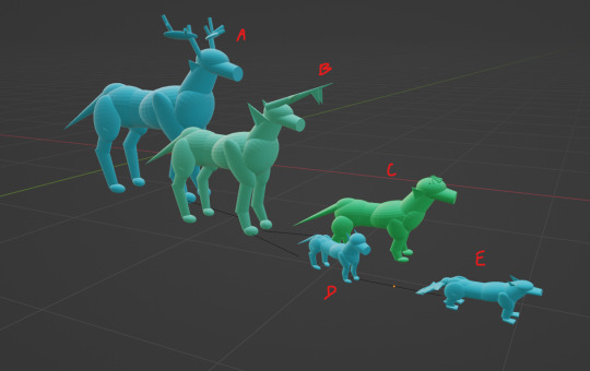
[Image ID: a screenshot of structurally simple models made with the computer program named Blender. Each model is constructed with distorted spheres, cylinders, and cones. There are five quadrapedal animals varying from shades of cyan to green, which all loosely resemble dogs in shape. The animals are labeled A through E, and vary in size. All have simple triangular ears. A and B are the largest and have elongated antlers or horns, while C has a ring of small cones on the front of the skull, resembling a tiara. D has no distinct features compared to the other animals but is the smallest. E is a similar size to D, has a flattened skull, webbed feet, and a flattened tail, much like a beaver. /.End ID] Here is the Dactylatus line! This is the first line of animals to have dominantly mammalian traits, including: tiny ear bones, cartilaginous ear... cup things, fur, and warm blood! Still laying eggs though. In this line we can see: letter a- Graminovoris Dactylatus itself! So cute <3 This guy is the first to have tails (which are made out of cartilage) letter b- D. Capihastis, who's horns are a combination of style and function-- they spear prey! These species tend to hunt in small packs. letter c- C. Cephalocoron, who's crowns are used during mating season, when males headbutt each other to settle disputes. letter d- C. Mustelidiformis, which pretty much fit what their name implies. They fill the same niches as mustelids. letter e- M. strerecastrumis, which are *drumroll* basically beavers. Some species in this clade fill other niches but are typically omnivorous.
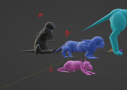
[Image ID: a screenshot of structurally simple models made with the computer program named Blender. Each model is constructed with distorted spheres, cylinders, and cones. There are three models fully visible varying in color and shape. The animal labelled A closely resembles a rabbit sitting up with its front limbs off the floor, and is gray. Animal A also has an elongated tail. The animal labelled B stands on four short small legs, with the front two feet being elongated to resemble claws. Animal B is gray. Animal C is pink and very closely resembles a lizard, however animal C has no tail, two hair-like fans on either side slightly behind the head, and a small third set of limbs emerge from beneath the fans. The limbs from the third set are shaped similar to the letter S. /.End ID] These are two different lines. letter a- G. Graminovoris, the form depicted is the extinct ancestor of both b and the dactylatus lines. G. Graminovoris went extinct during the most recent ice-age. This species did not have hair, but did have hair-like protrusions around chambers in which the front limbs are stored out of the way until needed for reproduction. letter b- G. ungulatheris, a separate lineage of G. graminovoris which is distinct for not developing the ears seen in dactylatus, or for developing true hair. These species boast quills and the same chambers seen in Graminovoris. letter c- Generatheris, which survived the ice age only due to its high metabolism and small size. This clade "hears" through the fans of whiskers above the reproductive limps, and does not have a tail.
6 notes
·
View notes
Text
maya
3D modelling… I cannot lie, I did not enjoy this project. I have a bit of experience with 3D modelling programs, because I’ve used Blender in the past, but I struggle a lot with visualising/working with things in 3D, so this was overall really frustrating for me.
I thought I’d go with a bit more of a simple shape for my building, so I chose a lighthouse. I figured it might be easier to work with just adding things to a cylindrical base.
It was in some ways pretty manageable? At least with the basic shapes. I struggled more with the roof, and there are some details I just didn’t include because they would’ve been really small and precise and I didn’t want to push myself into having a mental breakdown. So there’s no railing around the walkway. Health and safety hazard, but luckily this lighthouse isn’t gonna be built anywhere. The rock was fine. Had some fun trying to hold it into a vague rock shape. Does it look organic? Probably not. But it’s fine probably.
And then we got to the texture mapping and everything went downhill. I actually managed okay with the cylindrical parts, because that was easy enough, but oh boy this roof gave me so much trouble. So I gave up on it. I think it was an issue of not really being able to figure out why the texture map looked so weird, which then fucked up any application of actual textures on top. Maybe it’s because I used a cone shape and chopped off the top? Perhaps just a sphere chopped in half would’ve worked better? Unfortunately I did not have the patience to find out. I just wanted to be done with it as soon as possible.
Playing around with the lighting was pretty fun, though!
0 notes