#arduino human detection
Explore tagged Tumblr posts
Visit Tumblr Blog
Explore Tumblr blogs with no restrictions, modern design and the best experience.
Last Seen Tumblr Blogs


Fun Fact
After the announcement of the deal with Yahoo!, there were 170K signatures of unhappy Tumblr users petitioning to prevent the sale in 2013.
Text
Robotics Project Ideas for All Skill Levels: From Beginner to Advanced
Beginner Projects
Line Following Robot
Description: A robot that follows a pre-defined path marked by a line on the floor. The line can be of any color, but black on a white background is commonly used.
Components: Microcontroller (like Arduino), IR sensors, DC motors, motor driver, chassis, wheels.
Learning Outcomes: Basic electronics, sensor integration, and motor control.
Obstacle Avoidance Robot
Description: A robot designed to navigate its environment and avoid obstacles. It uses sensors to detect objects in its path and changes direction to avoid collisions.
Components: Ultrasonic sensors, microcontroller, motors, motor driver, chassis, wheels.
Learning Outcomes: Understanding of sensor data processing, basic programming, and control systems.
Bluetooth-Controlled Robot
Description: A robot that can be controlled via a smartphone or other Bluetooth-enabled devices. Commands are sent wirelessly to move the robot in different directions.
Components: Bluetooth module, microcontroller, motors, motor driver, chassis, wheels.
Learning Outcomes: Wireless communication, mobile app development, microcontroller programming.
Voice-Controlled Robot
Description: A robot that responds to voice commands, allowing you to control its movements through spoken instructions.
Components: Microphone, speech recognition module, microcontroller, motors, motor driver, chassis, wheels.
Learning Outcomes: Introduction to speech recognition, interfacing sensors, and control mechanisms.
Light Following Robot
Description: A robot that follows a light source. It can be used to follow a flashlight or navigate toward a lighted area.
Components: Light sensors, microcontroller, motors, motor driver, chassis, wheels.
Learning Outcomes: Sensor integration, basic electronics, programming.
Before next read this Robotic Revolution
Intermediate Projects
Self-Balancing Robot
Description: A robot that maintains its balance on two wheels, similar to a Segway. It uses sensors to detect its tilt and adjusts the motors to stay upright.
Components: Gyroscope, accelerometer, microcontroller, motors, motor driver, wheels.
Learning Outcomes: Understanding of feedback control systems, sensor fusion, and motor control.
Robotic Arm
Description: A robotic arm capable of performing simple tasks like picking and placing objects. It can be controlled manually or programmed to follow a sequence of movements.
Components: Servo motors, microcontroller, various sensors (like pressure or touch), structural components.
Learning Outcomes: Kinematics, servo control, programming for sequential tasks.
Maze-Solving Robot
Description: A robot that can navigate through a maze and find the exit. It uses algorithms to decide the best path and avoid dead ends.
Components: IR or ultrasonic sensors, microcontroller, motors, motor driver, chassis, wheels.
Learning Outcomes: Algorithm implementation, sensor data interpretation, navigation strategies.
Remote-Controlled Spy Robot
Description: A small robot equipped with a camera that can be controlled remotely to explore and send live video feed.
Components: Wireless camera, microcontroller, motors, motor driver, chassis, wheels, remote control.
Learning Outcomes: Wireless video transmission, remote control systems, motor and sensor integration.
Line Following Robot with Obstacle Detection
Description: A robot that not only follows a line but also detects and avoids obstacles on its path. It combines line following and obstacle avoidance features.
Components: IR sensors, ultrasonic sensors, microcontroller, motors, motor driver, chassis, wheels.
Learning Outcomes: Integration of multiple sensor data, complex programming logic, advanced control systems.
Advanced Projects
Humanoid Robot
Description: A robot designed to resemble a human body. It can perform tasks like walking, speaking, and interacting with its environment.
Components: Servo motors, microcontroller, sensors (accelerometer, gyroscope), structural components.
Learning Outcomes: Advanced kinematics, complex control algorithms, humanoid robotics.
Autonomous Delivery Robot
Description: A robot that can autonomously navigate to deliver packages within a designated area. It uses GPS and other sensors to determine its location and avoid obstacles.
Components: GPS module, ultrasonic sensors, camera, microcontroller, motors, motor driver, chassis, wheels.
Learning Outcomes: Autonomous navigation, path planning, integration of multiple sensors.
Robotic Exoskeleton
Description: A wearable robotic suit that can assist with movement, enhancing the strength and endurance of the user.
Components: Servo motors, sensors (like pressure, motion), microcontroller, structural components.
Learning Outcomes: Biomechanics, actuator control, wearable robotics.
Quadruped Robot
Description: A four-legged robot capable of walking, running, and navigating various terrains. It mimics the movement of animals like dogs or cats.
Components: Servo motors, microcontroller, sensors (accelerometer, gyroscope), structural components.
Learning Outcomes: Gait analysis, dynamic stability, complex movement programming.
Swarm Robotics
Description: A group of small robots that work together to complete tasks. They communicate and coordinate to achieve goals like collective exploration or object transport.
Components: Multiple small robots, communication modules, microcontroller, various sensors.
Learning Outcomes: Distributed systems, communication protocols, cooperative robotics.
2 notes
·
View notes
Text

The TTP224 is a 4-Channel Touch Sensor, meaning it has four touchpads. Whenever a capacitive load such as human hands is brought in proximity with the sense pad, the sensor then senses the change in capacitance and activates the switch. Custom sense-pads can be made from nearly any conductive material and these sensors can detect touch through thin layers of non-conductive materials such as glass, plastic, fabric or even wood. Each Touchpad has its respective output pin when the user touches a pad, the corresponding output pin will go high. It is very easy to interface with microcontrollers like Arduino to control different applications as a switch. It can be used in home automation, motor control, Relay control, etc. the module basically gets rid of the push button troubles.
6 notes
·
View notes
Text
10 Fun Robotics Projects You Can Build at Home!
Learning robotics doesn’t require a fancy lab or expensive equipment. With a bit of curiosity, basic tools, and beginner-friendly kits, anyone can start building robots right from the comfort of home. Whether you’re a student, parent, or hobbyist, these 10 fun robotics projects are perfect for hands-on learning and creative exploration.
1. Line-Following Robot
What it does: Follows a black line path on the ground using infrared sensors.
Tools: Arduino, IR sensors, motor driver, wheels.
Why it’s fun: Teaches sensor logic, control loops, and navigation basics.
2. Obstacle-Avoiding Robot
What it does: Moves forward and changes direction when it detects an object.
Tools: Ultrasonic sensor, Arduino, servo motor.
Why it’s fun: Demonstrates real-world robotics applications like autonomous vehicles.
3. Light-Following Robot
What it does: Moves toward a light source using photoresistors.
Tools: LDRs (light sensors), Arduino, motors.
Why it’s fun: Kids love watching their robot "chase" a flashlight!
4. Robotic Arm
What it does: Mimics a human arm to pick and place small objects.
Tools: Servo motors, Arduino, cardboard or 3D-printed parts.
Why it’s fun: Great for learning about mechanical motion and servo control.
5. Remote-Controlled Car
What it does: Controlled wirelessly via Bluetooth or smartphone.
Tools: Arduino, Bluetooth module (like HC-05), motor driver.
Why it’s fun: Combines robotics with app-based interaction.
0 notes
Text
Understanding Mechatronics: A Beginner’s Guide for Freshers
If you’ve just stepped into the world of engineering or are considering which specialization to pursue, you might have come across the term Mechatronics. It sounds futuristic—and honestly, it is. But what exactly is it? Is it mechanical? Is it electronics? Or is it something else altogether?
Let’s break it down and make it simple for you.
What Is Mechatronics?
Mechatronics is an interdisciplinary field that blends mechanical engineering, electronics, computer science, and control engineering. It’s all about designing and creating smarter machines—systems that not only move or perform tasks but also think and respond intelligently.
Think of things like self-driving cars, robotic arms in factories, automated coffee machines, or even drones that maintain stability mid-air. All of these rely on the principles of mechatronics.
This discipline is becoming essential in today’s automation-driven world, especially with the rise of Industry 4.0, where machines communicate with each other to optimize performance without human input.
Why Should You Care as a Fresher?
In the early stages of your engineering journey, it's important to understand where the future is headed. Mechatronics is one of those areas that’s not just growing—it’s exploding.
As a fresher, you might still be figuring out what excites you most. But if you're someone who enjoys blending creativity with technology—imagine coding a program and then watching it control a real robot—this field will likely click with you.
Also, if you eventually want to work in automation, AI-driven systems, or robotics, mechatronics offers you the foundation and flexibility to go in multiple directions.
What Will You Learn in Mechatronics?
Typically, if you pursue mechatronics as a core subject or even as an elective, you’ll dive into areas like:
Sensors and Actuators: Devices that help machines sense their environment and act accordingly.
Microcontrollers and Embedded Systems: The brains of most modern electronic machines.
Mechanical Design: Basics of gears, motors, and structures that move.
Control Systems: How to ensure a robot does what it’s supposed to—no more, no less.
Programming: Often in C/C++ or Python to control the devices.
You may also get your hands on software like MATLAB, Simulink, or Arduino IDE early on.
How to Get Started in College
You don't have to wait till the third year to explore mechatronics. In fact, some colleges start offering related workshops and certifications right from the first year. If you're studying in a place where the labs are well-equipped and faculty are research-active, you'll probably get the chance to work on actual robots or automation systems before you graduate.
During a visit to a lab at NMIET Bhubaneswar, I noticed students working on automated vehicle prototypes that used sensors for obstacle detection. It struck me how mechatronics isn’t just a theoretical subject in such institutions—it’s hands-on and real.
Career Scope: Where Can Mechatronics Take You?
Mechatronics engineers are highly valued in sectors like:
Robotics and Automation
Aerospace
Automobile Manufacturing
Medical Equipment Development
Home Automation and Smart Devices
With increasing reliance on smart systems and AI-driven hardware, companies are actively seeking engineers who can work across domains. This is where mechatronics gives you a massive edge.
Even core mechanical or electrical engineers are now advised to pick up basic knowledge of microcontrollers or coding. So, if you're already in a college that encourages learning beyond your core, you're in the right place.
What Makes a Good College for Mechatronics Learning?
Let’s be honest—your learning environment plays a big role. Access to automation labs, exposure to industry tools, faculty who encourage innovation, and the chance to work on real-world projects—these are the things that matter most.
Some of the top engineering colleges in Odisha are already introducing mechatronics modules in mechanical and electronics streams. The goal is to create engineers who can build, code, and innovate.
It’s always a good idea to look into whether the institute collaborates with industries for internships and whether they have tie-ups for campus placements with companies involved in automation or robotics.
Final Thoughts: A Future-Proof Path
Mechatronics is not just another subject—it’s a mindset. It teaches you to look at machines not just as static components, but as intelligent systems that interact with the world.
As a fresher, you don’t need to master it all at once. Start with basic projects—maybe build a line-follower robot or an automatic light system. Join clubs, take up online certifications, and most importantly, stay curious.
If you’re in an environment where creativity and cross-disciplinary learning are encouraged—like the one I saw at NMIET—you’re already ahead of the curve.
So, if you’re dreaming of working on robots, smart devices, or even futuristic innovations we haven’t seen yet—mechatronics might just be the path you’ve been looking for.
#bhubaneswar b tech colleges#college of engineering bhubaneswar#best engineering colleges in orissa#best engineering colleges in bhubaneswar#best private engineering colleges in odisha#best engineering colleges in odisha
0 notes
Text
A Passive Infrared (PIR) sensor detects infrared radiation emitted by objects, especially humans. The sensor outputs a digital signal (HIGH or LOW) depending on whether it senses motion. It’s called "passive" because it doesn’t emit any energy; it just senses the infrared rays from the surrounding environment.
How PIR Sensors Work:
The PIR sensor consists of two key components:
Pyroelectric sensor: Detects infrared radiation.
Fresnel lens: Focuses the IR signals on the pyroelectric sensor. When a warm body (like a human) moves across the sensor’s field of view, the infrared radiation changes, and the sensor detects this change, sending a HIGH signal.
Components Required:
Arduino (e.g., Uno, Nano, or Mega)
PIR Sensor
Jumper Wires
Breadboard
LED (for visual feedback)
220Ω Resistor (for the LED)
Circuit Diagram:
sql
Copy code
[Insert a simple diagram showing the connections between Arduino, PIR sensor, and LED]
Connections:
Connect the VCC pin of the PIR sensor to the 5V pin of the Arduino.
Connect the GND pin of the PIR sensor to GND on the Arduino.
Connect the OUT pin of the PIR sensor to digital pin D2 on the Arduino.
Optionally, connect an LED to pin D13 (with a 220Ω resistor for safety) to provide a visual indicator when motion is detected.
Arduino Code:
Now that you have connected the PIR sensor, let’s upload some code to the Arduino. The following code reads the PIR sensor’s output and lights up an LED when motion is detected.
cpp
Copy code
// PIR Sensor Pin Definitions
int pirPin = 2; // Connect the PIR sensor output pin to D2
int ledPin = 13; // LED pin (optional for motion indication)
void setup() {
pinMode(pirPin, INPUT); // PIR sensor as input
pinMode(ledPin, OUTPUT); // LED as output (optional)
Serial.begin(9600); // Initialize Serial Monitor
}
void loop() {
int pirState = digitalRead(pirPin); // Read PIR sensor's output
if (pirState == HIGH) { // Motion detected
digitalWrite(ledPin, HIGH); // Turn on LED
Serial.println("Motion detected!");
} else { // No motion
digitalWrite(ledPin, LOW); // Turn off LED
Serial.println("No motion");
}
delay(1000); // 1 second delay between readings
}
Explaining the Code:
pinMode(): Defines whether the pin is an input or output.
digitalRead(): Reads the PIR sensor output (HIGH or LOW).
digitalWrite(): Controls the LED based on sensor output.
Serial.begin(): Starts serial communication for debugging.
When the PIR sensor detects motion, the pirState variable becomes HIGH, turning on the LED and printing "Motion detected!" to the serial monitor.
Testing the Setup:
Connect your Arduino to your computer and upload the code.
Open the Serial Monitor from the Arduino IDE (Tools > Serial Monitor).
Wave your hand in front of the PIR sensor to test if it detects motion.
If motion is detected, the LED will light up and the message will appear in the Serial Monitor.
Adjusting the PIR Sensor Sensitivity:
Most PIR sensors come with two potentiometers for adjusting sensitivity and delay time. Sensitivity determines the range of detection, and delay time sets how long the output remains HIGH after motion is detected.
Sensitivity Potentiometer: Rotate to increase or decrease detection range.
Delay Time Potentiometer: Adjust how long the PIR sensor output stays HIGH after motion.
Applications of PIR Sensors:
Home Security Systems: Detect intruders and trigger alarms or cameras.
Smart Lighting: Automatically turn lights on when someone enters a room.
Automatic Door Openers: Use PIR sensors to detect approaching people and open doors.
Energy-Efficient Devices: Turn off appliances or lights when no motion is detected, reducing power consumption.
Troubleshooting:
False Positives: If the sensor triggers without motion, reduce the sensitivity or place the sensor in a more controlled environment.
No Motion Detection: Double-check the wiring and ensure that the sensor is properly powered and connected to the correct pins.
Conclusion:
You have successfully interfaced a PIR sensor with an Arduino to create a basic motion detection system. This simple project can be expanded into various applications like security alarms, smart home systems, and automation projects.
By following this blog, beginners will get a solid foundation in interfacing a PIR sensor with an Arduino. Advanced users can add features like buzzer alarms, wireless communication, or integra
ChatGPT can make mist
0 notes
Text
Research Publications of Electronics and Communication Engineering Department
https://krct.ac.in/blog/2024/05/25/research-publications-of-electronics-and-communication-engineering-department/
Research Publications of Electronics and Communication Engineering Department
In the fast-paced world of Electronics and Communication Engineering (ECE), staying abreast of the latest developments and breakthroughs is essential. From advancements in wireless communication to novel materials for electronic applications; researchers in this field are constantly pushing the boundaries of what's possible. Here, in this blog post, we will explore into some January to March 2023 Research publications from ECE department at KRCT. Further, this highlights the diverse and innovative research being conducted in ECE.
Journal Research Publications JAN -MARCH 2023
Faculty Name: Dr. B. Balraj
Title of the paper: Green hydrothermal synthesis of Ga doping derived 3D ZnO nanosatellites for highly sensitive gas sensors/Sensors and Actuators B: Chemical/SCI/SCIE/March-2023
Faculty Name: Dr. B. Balraj
Title of the paper: Two steps green plasmonic synthesis of Gd3+/Nd3+ ions influenced ZrO2 nanoparticles for enhanced in-vitro antibacterial, antifungal and antidiabetic activities/SCI/ SCIE/Febrauary-2023
Faculty Name: Dr. M. Kavitha
Title of the paper: MDP-HML: an efficient detection method for multiple human disease using retinal fundus images based on hybrid learning techniques/Multimedia Systems/SCI SCIE/January-2023
Faculty Name: Dr. S. R. Barkunan
Title of the paper: Reinforcement of Nanocellulose as Green Agent in the Electronic Applications Associated with the Composites of Polymer Matrix/International Journal of Polymer Science /SCI/SCIE/January 2023
Faculty Name: Mrs. J. Deepa
Title of the paper: Design of Metamaterial Antenna Based on the Mathematical Formulation of Patch Antenna Application/International Journal of Propagation/SCI/SCIE/Apr 2023 for Wireless Antennas and
Faculty Name: Mr. P. Mani
Title of the paper: IoT Based RFID Attendance Monitoring System of Students using Arduino ESP8266 & Adafruit. io on Defined Area /International Journal of Propagation/Cybernetics and Systems Antennas and /SCI/SCIE/January 2023
Importance of Research Publications
At KRCT's ECE department, research publications are components of driving innovation and technological progress more than just academic exercises. Here's why they are important:
Research enables faculty members and students to explore new ideas, theories, and technologies. Further, this expands the boundaries of knowledge in their respective fields.
Additionally, through research, academics tackle real-world challenges head-on and develop innovative solutions. Consequently, these solutions address pressing issues and improve quality of life.
By publishing their findings, researchers contribute to the collective body of knowledge. Moreover, this dissemination of knowledge inspires further innovation and collaboration within the academic community and beyond. Hence, it develops a culture of continuous learning and improvement.
High-quality research and publications play a crucial role in enhancing the reputation of KRCT's ECE department. Consequently, this positioning as a leader in the field attracts top talent, collaborations, and funding opportunities, further fuelling research excellence and impact.
Above all, research opportunities provide students with invaluable hands-on experience, critical thinking skills, and the opportunity to work alongside faculty mentors. As a result, students are well-prepared for successful careers in academia, industry, and research, equipped with both theoretical knowledge and practical skills.
To Conclude
Research publications are integral to the mission of KRCT's ECE department, driving innovation, advancing knowledge, and shaping the future of technology. Through their dedication to excellence in research, faculty members and students at KRCT are making significant contributions to the field of Electronics and Communication Engineering, paving the way for a brighter and more technologically advanced future.
#top college of technology in trichy#best autonomous college of technology in trichy#krct the best college of technology in trichy#k ramakrishnan college of technology trichy#the best engineering college for ai
0 notes
Text
ST ultra-low power time-of-flight sensor: unlocking new scenarios in smart life

【Lansheng Technology News】In the future, ToF will be immeasurable in applications in areas such as proximity detection sensors, human presence detection, and laser autofocus. As a major provider of ToF technology and solutions, STMicroelectronics continues to update and iterate product technologies to meet these application needs.
In order to achieve the lowest power consumption of time-of-flight sensors, ST has developed a set of drivers that effectively configure the FlightSense™ sensor as an energy-saving version of the proximity detector. Additionally, once an object is detected, the driver immediately switches the sensor back to standard ranging mode, taking full advantage of Time-of-Flight (ToF) technology. The sensor is specially designed so that its setup and ranging processes are fully embedded in the firmware, significantly reducing power consumption.
ST's FlightSense™ single ranging sensors with ultra-low power (ULP) mode mainly include three products: VL53L1CX, VL53L3CX, and VL53L4CD.
The VL53L1CX is capable of detecting objects at distances up to 1400 mm in ULP mode with a ranging frequency of 1 Hz and a current consumption of only 65 μA. The ultra-low power driver (STSW-IMG032) easily sets the VL53L1CX FlightSense™ sensor to ULP mode for use as an energy-saving proximity detector. Once the sensor detects an object, the driver will immediately switch the sensor back to ranging mode, with accurate ranging distances up to 4 meters, high ranging frequency (50 Hz) and customizable field of view (FoV) functions. The lowest power consumption is 65 µA at 800 mm, and 300 µA at the longest detection distance of 1400 mm.
The VL53L3CX is capable of detecting objects at distances up to 840 mm in ULP mode with a ranging frequency of 1 Hz and a current consumption of only 55 μA. The ultra-low power driver (STSW-IMG033) makes it easy to set the VL53L3CX FlightSense™ sensor to ULP mode for use as an energy-saving proximity detector. Once the sensor detects an object, the driver immediately switches the sensor back to full histogram ranging mode, using ST's histogram algorithm for accurate multi-target ranging up to 5 meters, cover-chip crosstalk immunity of over 80 cm, and With dynamic stain compensation function. The lowest power consumption is 55 µA at 230 mm, and the longest detection distance is 240 µA at 840 mm.
The VL53L4CD is capable of detecting objects at distances up to 1100 mm in ULP mode with a ranging frequency of 1 Hz and a current consumption of only 55 μA. The ultra-low power driver (STSW-IMG034) makes it easy to set the VL53L4CD FlightSense™ sensor to ULP mode for use as an energy-saving proximity detector. Once the sensor detects an object, the driver immediately switches the sensor back to ranging mode, extending the accurate ranging distance from just 1 mm to 1300 mm. It is also equipped with a new generation 18° FoV laser transmitter, which improves performance under ambient light conditions, and its ranging speed can reach 100 Hz. The lowest power consumption is 55 µA at 310 mm, and the longest detection distance is 240 µA at 1090 mm.
Target application
ST ultra-low-power time-of-flight (ToF) sensors can be used in a variety of smart life scenarios such as smart faucets, smart toilets, smart urinals, smart trash cans, coffee machines, and vending machines.
Complete development toolset
ST provides comprehensive application design support services to help users take full advantage of these sensors, speed up product launch, and reduce design risks.
The VL53L1CX development tools include the VL53L1CX expansion board for STM32 Nucleo and two VL53L1CX adapter boards. The VL53L1CX expansion board is a ready-to-use VL53L1CX evaluation kit with an adjustable cover holder and comes with an Arduino UNO R3 connector and complete system software including example code and graphical user interface. Two VL53L1CX breakout boards can be connected via two 10-pin connectors.
The VL53L3CX development tools include the VL53L3CX expansion board for STM32 Nucleo and two VL53L3CX adapter boards. The VL53L3CX expansion board is a ready-to-use VL53L3CX evaluation kit with an adjustable cover holder and comes with an Arduino UNO R3 connector and complete system software including example code and graphical user interface. Two VL53L3CX breakout boards can be connected via two 10-pin connectors.
The VL53L4CD development tools include the VL53L4CD expansion board for STM32 Nucleo and two adapter boards based on VL53L4CD. The VL53L4CD expansion board is a ready-to-use VL53L4CD evaluation kit with an adjustable cover holder and comes with an Arduino UNO R3 connector and complete system software including example code and graphical user interface. Two adapter boards based on VL53L4CD for easy integration.
Lansheng Technology Limited, which is a spot stock distributor of many well-known brands, we have price advantage of the first-hand spot channel, and have technical supports.
Our main brands: STMicroelectronics, Toshiba, Microchip, Vishay, Marvell, ON Semiconductor, AOS, DIODES, Murata, Samsung, Hyundai/Hynix, Xilinx, Micron, Infinone, Texas Instruments, ADI, Maxim Integrated, NXP, etc
To learn more about our products, services, and capabilities, please visit our website at http://www.lanshengic.com
0 notes
Text
Okay wait - gears are turning in my engineer brain - what if the puppetry was done mechanically? I'm not that familiar with how Vtuber setups work, but as I understand it there's a camera or sensors that detect the Tuber's facial movement and expressions, then that data gets fed into an animation program that applies animations to the digital avatar.
But what if you fed that face-tracking data into a set of arduinos and servo motors that were operating a puppet? And then the online stream would be a video feed of the puppet. That way you could have a physical puppet Vtuber streamer without needing a human puppeteer.
Wait. I'm describing an animatronic. Would be pretty funny for a FNAF stream though
I understand there are solid financial reasons we'll probably never see a true "practical effects" vtuber – it'd basically need to be a three-person operation, two to work the muppet and a third off camera actually playing the game, and it's hard enough supporting one person on a vtuber's paycheque – but, well, a guy can dream, right?
2K notes
·
View notes
Text
DESIGN AND CONSTRUCTION OF A HUMAN DETECTION ROBOT
DESIGN AND CONSTRUCTION OF A HUMAN DETECTION ROBOT
DESIGN AND CONSTRUCTION OF A HUMAN DETECTION ROBOT
ABSTRACT
The circuit breaker is an absolutely essential device in the modern world, and one of the most important safety mechanisms in your home. Whenever electrical wiring in a building has too much current flowing through it, these simple machines cut the power until somebody can fix the problem. Without circuit breakers (or the alternative,…
View On WordPress
#3d human sensing slideshare#alive human detection robot for disaster management#android control robot using 8051#arduino human detection#arduino pedestrian detection#bomb detection robot circuit diagram#DESIGN AND CONSTRUCTION OF A HUMAN DETECTION ROBOT#disadvantages of human detection robot#how to make human detection sensor#human detection by live body sensor#human detection pdf#human detection robot ppt#human detection robot using arduino pdf#human detection robot using raspberry pi#human detection sensor for home automation#human detection using arduino#human detector sensor#human speed detection project using pic#iot based robotics projects#live human being detection wireless remote controlled robot#metal detector robot#metal detector robotic vehicle ppt#pir sensor#pir sensor working#rf section in metal detector#sensor to detect human body
0 notes
Text
What Do Player Pianos, IBM Punchcards, Telepathy and Elon Musk’s Neuralink Have In Common?

This is a player piano punch sheet or score taken from a rolled up drum. The holes make the keys move. It is a very simple pattern that translates into musical notes.

This is a decoding of “neural spikes” according to scientists at Elon Musk’s brain computer company Neuralink. The spikes are pictured in single boxes, and many spikes when they fire make a pattern. From that pattern you can begin to decode thought. According to Neuralink, “Everything you hear or think is all action potentials, its action spikes and it feels so real, it feels very real.”
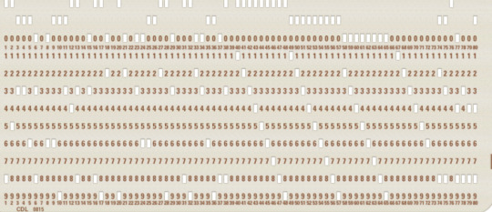
This is an early IBM computer punch card, and the basic pattern recognition of the presence or absence of holes in predefined patterns led to everything we know today about computers. Though IBM introduced the first cards in 1928, they had already been in use to ‘program’ cloth in the Jacquard loom in 1804, making gorgeous silks and tapestries.

I think we are basically back in the same position as we were when IBM first made the computer punch card in 1928 in terms of brain research and decoding thought. Neuralink is putting together elements in brain research that 100 years from now, or even 50 years from now will have tremendous repercussions. The company did not invent all of the aspects of technology it is using to put things together, but they did improve upon existing tech and brought it all together.
THE SURGICAL ROBOT

The Neuralink robot doing an implantation
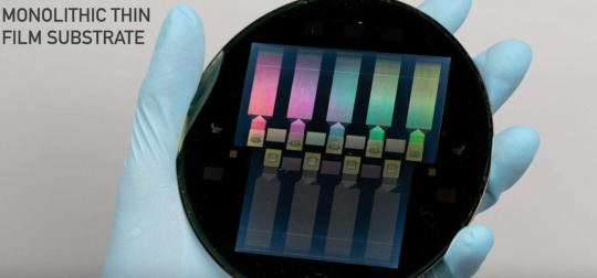
Neuralink works by extracting electrical signals from neurons. In order to do that it has to implant extremely thin wires in the brain to access and read those signals onto a nanochip. Before it can do that, it has to make a precision surgical robot machine operated by neuroscientists to insert the wires - so it did. Apparently there was some DARPA money thrown into the mix somewhere along the way. The robotic surgeon has to implant tiny wires in between blood vessels and neurons, not on them. This can only be achieved through microscopes and nanometer precision. The implant needle is 24 microns small. Tiny threads are about 1/10 of a human hair, which is about the same size as a neuron. The needle to implant the wire is 24 microns small. You can open the skull, insert the threads, put in a tiny chip, and then glue the skull shut. The chip functions as a wireless bluetooth signal.
THE WIRES
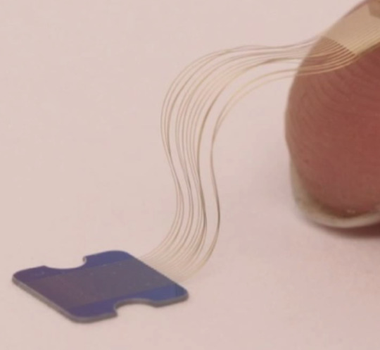
This picture shows thin nano threads pasted onto a fingertip. The thinness of this wire is the big issue DARPA was trying to solve with Moldavian wire from Paradromics, that I previously blogged about in 2017, but Musk beat them to the punch. He wrote about his breakthroughs here.

This is the different new design of the threads called a “linear edge”, which are made of layered polymers. They are so are super duper thin they can’t bee seen with a human eye, so they need the special robot that inserts the threads onto the surface of the brain. Another reason is the brain’s surface moves with inhalation and exhalation, and the robot can account for this natural movement. The wires and chip have to record the output from neurons. They are micro fabricated as precisely as the size of an electron beam. It is important to separate the signal to noise ratio in the chips, as they work with nanometer sizes of light. A new design. 350 nanometers,is smaller than visible light.

This image is the crux of how Neuralink acquires the signal. Here you see the neuron sending out an electrical spike and a thread next to it picking up the impulse. The electrical spike is the bulls eye. The copper colored needle is actually the implanted wire thread. You need to be 60 microns away or less to read the signals, so you really need to be under the skull. This is a graphic representation

This is a photo of the real thing, with lots of wires precision implanted into brain tissue. If you look really closely you will see they skirt around the blood vessels and neuron branches, but don’t touch any of them. Its sort of like an amazing game of darts, but the goal is to miss the bull’s eye of the vessels.
HISTORY OF IMPLANT CHIPS
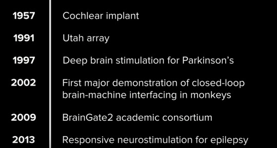
This is a short history of brain research about making chips to implant in the brain. At this point the Utah array is still the most used implant chip in academia. Neuralinks chips are way, way faster and smaller. Their research builds on a century of neuroscience research and a decade of neuro engineering research. More advanced applications with advanced innovations will follow.
CHIPS AND PODS
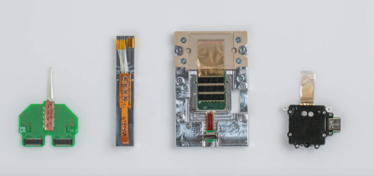
These are early iterations of chips and devices made by Neurlink. Looks like Arduino 101, more or less.

The N1 sensor - the beginning of the sophisticated bean sized implant that goes into the skull and contains the chips.
The actual chips are made on super thin nano wafers in a hermetic environment so there is no dust. They are also super duper thin. A 4 x 4 millimeter chip has a thousand electrodes,and implanting up to 10 chips is feasible. At this point the best FDA approved chip implant for Parkinsons Disease only has 10 electrodes. The Neuralink chips read and write, and are 1000 times more powerful than what is publicly approved. They will get better with newer versions.

Shades of Cyborg Neil Harbisson and his Eyeborg! The Neuralink implant with four chips receive information from the threads, and sends them to an output area for batteries and firmware.

This is the size of the output piece, like an earphone.You can upgrade the firmware on the pod on the ear, it is not the actual implant but connects to it. It will be controlled through an iPhone app. Probably Android as well.
SIGNAL PROCESSING

Waves of neural spikes from an array from implanted threads that are being read out on a computer. monitor The color screen shows the brain at work, and traces of electrodes from single threads. Each trace is a voltage waveform in time. If you focus on one trace, it shows voltage deflections, or spikes per wave. It occurs when a neuron has an action potential, because that is the core information that is recorded. Then the algorithm is decoded, which means capturing the intended information. You just have to think about something and build up the decoding data from that information or thought, and you can begin to interpret movement, memory, and many other different types of experiences.
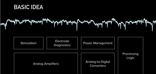
This is a basic diagram of signal processing from the chip - how they get the stuff out of the wires and threads to actually show the spikes. Neuralink said “Everything we care about is contained in the statistics of spikes (inside the brain).” So it goes back to the basic IBM punchcards, or the player piano drum roll - decipher the pattern and you decipher the thought.

Here is their basic logic analogue to digital conversion that is necessary to change action potential spikes to computer code..Calling Alvin Lucier, John Cage, Nam June Paik, David Rosenboom, Richard Teitelbaum - or Duh, this has been going on with the brain, changing analog to digital since 1965 in the music world.
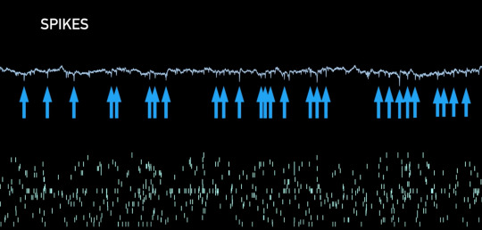
Spike rasters in the brain - The top is the brainwave spikes pointed at by the blue arrows, and the bottom is the beginning of pattern recognition of individual neurons. There should be one pixel per electrode. They are on-chip spike detectors. The methods for detection are thresholding signals or directly characterizing the shape. The Neuralink scientists claim they can identify different neurons from same electrode based on their shape. The engineers had to modify the algorithms and scale them to compress neural data up to 200 times. It takes only 900 nano seconds to compute the signal, faster than the brain knows that the signal even occurred. They can also stimulate any combination of up to 64 channels

One good use of this in the next few years is creating visual feedback for the blind by targeting the visual cortex to create an image better than a dot matrix image - or computer vision basics meets brain wetware. The scientists want to not only read out, but read into the brain. You can read into the brain by passing a current in the electrode. This causes the cell to fire an action potential, like for cochlear implants, or a way for the eye to restore vision. You can also use this technique in the brain to restore the sense of touch or vision. The visual cortex has maps, a spatial map (orange section of the brain in graphic). If you stimulate a point in that area, a blind person sees a point of light or phosphene. The idea is you can stimulate areas of the brain in the visual cortex to resemble a dot matrix level of the world. There are also parts of the brain that control orientation, color, size and speed of moving objects, and once you figure out what they are, and where to stimulate them, you can generate a more comprehensive image that a blind person can experience. Neuralink wants a device with electrodes that are small enough, but with high density that can do better than a dot matrix image.
The first iteration of their implant will have three different types that can go from a mobile device to a mouse or keyboard on a Bluetooth signal. Neuralink needs to get FDA approval. Right now they are working on patients with complete paralysis so it is for serious neurological needs, and idea is to make it really safe.

Who needs Google maps when you can tap into someone’s brain algorithm in their Hippocampus which contains spatial orientation. Here is a rendition of someone who really knows San Francisco, and they can send you pattern signals as you wander through the park and direct you telepathically - voila!
THE PURPOSE
Musk gave a number of reasons for his very public video presentation. The first he shamelessly admitted, was to recruit for new talent to Neuralink. He then framed the motivation of his company as wanting to solve brain ailments, spinal disorders, or catastrophic injuries like a broken neck or spine,. He admitted it won’t happen quickly, and kept mentioning the need for FDA approval. He wants to make his devices as cheap and accessible as a Lasik-like device.
“Hopefully,” he said, “AI is a benign scenario. You can chose to have a neural implant if you want, it is not a mandatory thing... We already have digital super intelligence - our access to a computer and a smart phone. The input speed in the human brain is fast, due to our vision, but the output speed is slow because we have to type information into a computer. We are constrained by human bandwidth and mechanics. “
But then he dropped the Neuralink AI bomb - that he believes that we “ultimately (will) achieve a symbiosis with artificial intelligence” (if you want it at a civilization level scale). Then he added, “two people with Neuralink could have telepathy, a new kind of communication, conceptual telepathy, it has to be consensual”.
So the new “me too” movement will concern having consensual telepathy #metooconsensualtelepathy.
*Screen shot photos all taken from publicly available Neuralink YouTube video here.
7 notes
·
View notes
Text
AAAAAAAAAAAA
It's the weekend before finals weeks and i just submitted my abstract for an undergraduate conference at my university
Thanks all for keeping up with my research so far.
Read it below:
End-to-end neural networks (EENN) utilize machine learning to make predictions or decisions without being explicitly programmed to perform tasks by considering the inputs and outputs directly. In contrast, traditional hard coded algorithmic autonomous robotics require every possibility programmed. Existing research with EENN and autonomous driving demonstrates level-two autonomy where the vehicle can assist with acceleration, braking, and environment monitoring with a human observer, such as NVIDIA's DAVE-2 autonomous car system by utilizing case-specific computing hardware, and DeepPiCar by scaling technology down to a low power embedded computer (Raspberry Pi). The goal of this study is to recreate previous findings on a different platform and in different environments through EENN application by scaling up DeepPiCar with a NVIDIA Jetson TX2 computing board and hobbyist grade parts (e.g. 12V DC motor, Arduino) to represent 'off-the-shelf' components when compared to DAVE-2. This advancement validates that the concept is scalable to using more generalized data, therefore easing the training process for an EENN by avoiding dataset overfitting and production of a system with a level of 'common sense'. Training data is collected via camera input and associating velocity and encoder values from a differential drive ground vehicle (DDGV) with quadrature motors at 320x240 resolution with a CSV database. Created datasets are fed into an EENN analogous to the DAVE-2 EENN layered structure: one normalization, five convolutional, three fully connected layers. The EENN is considered a convolutional neural network (assumes inputs are images and learns filters, e.g. edge detection, independently from a human programmer), and accuracy is measured by comparing produced velocity values against actual values from a collected validation dataset. An expected result is the DDGV navigates a human space and obstacles by the EENN only inputting sensor data and outputting velocities for each motor.
12 notes
·
View notes
Text
How to interface an IR sensor with an Arduino?
Are you interested in learning about how to interface an IR sensor with an Arduino? In this post, we’ll go over the basics of what an IR sensor is, how it works, and how to connect it to an Arduino to create your own projects.
First, let’s talk about what an IR sensor is. IR stands for infrared, which is a type of electromagnetic radiation that is invisible to the human eye. An IR sensor is a device that detects this radiation and converts it into an electrical signal that can be processed by a microcontroller, like an Arduino.
There are different types of IR sensors available, but the most common one is the IR receiver module. This module has a photodiode that detects IR radiation and a preamplifier that amplifies the electrical signal produced by the photodiode. The output of the module is a digital signal that can be interpreted by the Arduino.

Now, let’s see how we can connect the IR receiver module to an Arduino. The module has three pins: VCC, GND, and OUT. VCC should be connected to the 5V pin on the Arduino, GND should be connected to the GND pin, and OUT should be connected to a digital input pin, like pin 2.
To read the signal from the module, we can use the Arduino’s built-in pulseIn() function. This function measures the duration of a pulse in microseconds and returns the value as an integer. We can use this value to determine the type of IR signal that was received.
For example, if we want to detect signals from a TV remote control, we can use the pulseIn() function to measure the duration of the pulse and compare it to the known values for each button on the remote. We can then use the Arduino to perform an action based on which button was pressed.
In conclusion, interfacing an IR sensor with an Arduino is a great way to create your own projects that can detect and respond to IR signals. With just a few components and some basic programming skills, you can create your own remote control, home automation system, or other cool projects. So why not give it a try and see what you can create?
Do check out the full article and Arduino code at IR sensor interfacing with Arduino
0 notes
Text
Robot helps detect contaminants in water after sewage treatment
- By Cristiane Paião , Agência FAPESP -
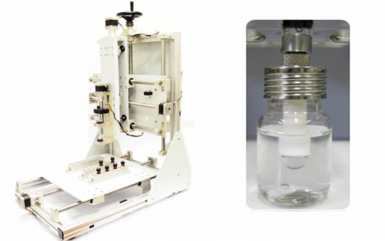
Researchers at the University of São Paulo (USP) in Brazil have developed a robot to automate the analysis of wastewater after sewage treatment, enhancing the precision of the results and reducing the use of costly and toxic solvents.
The research was conducted at the São Carlos Institute of Chemistry (IQSC-USP) during the doctorate of Marcio David Bocelli, with FAPESP’s support and supervision by Professor Álvaro José Santos-Neto. The results are reported in an article published in the journal Electrophoresis.
The purpose of the research was to detect the presence of parabens in samples of treated wastewater. Parabens are synthetic chemicals used as preservatives in a wide array of cosmetics, personal hygiene products, food products and pharmaceuticals, to prevent the growth of harmful bacteria and mold, for example. They cause allergies in some people, and there is evidence that they can disrupt hormones, harm fertility and reproductive organs, affect birth outcomes, and increase the risk of cancer. They are also harmful to aquatic animals.
“Water contaminated by parabens goes through the sewage plant, but unless the treatment removes them, they pass along to rivers and water sources, which they pollute. The existing wastewater analysis technique is manual and depends a great deal on the skill of the analyst. Some of our students take almost a year to master it. This is why we set out to automate the process,” Santos-Neto told Agência FAPESP.
The group used a well-known technique called dynamic single-drop microextraction but automated the syringe that performs the extraction process. The robot and the device that stabilizes and inserts the drops are being patented. A single droplet of solvent is sufficient for each analysis. In addition to reducing costs, the system increases the safety of laboratory workers.
“This type of analysis is almost always performed by traditional methods, using many liters of toxic and expensive solvents,” Bocelli said. “There has to be a paradigm shift if this project is to become a reality, and that depends on the stance taken by institutions and private enterprise. They need to understand the benefits associated with miniaturization and robotization, especially cost reduction and environmental protection.”
Process of analysis
The research was conducted as part of the Thematic Project “Single-drop chromatography and its coupling to mass spectrometry: instrumental strategies, development of materials, automation and analytical applications”, for which the principal investigator is Fernando Mauro Lanças. The other authors of the article are Deyber Arley Vargas Medina, who is also funded by FAPESP, and Julie Paulin García Rodriguez. All five co-authors are affiliated with IQSC-USP.
According to Santos-Neto, one of the group’s primary aims is to develop novel equipment that will assist routine chemical analysis. The reason for focusing on parabens in this study was that they can be a human and animal health hazard.
Advances are needed in different scientific areas to demonstrate the link between parabens and cancer, he said, but the fact is that they can behave as pollutants, and alternatives should be found in the service of environmental protection.
“There are cases where treatment does actually remove these contaminants. Wastewater can be cleansed of several micropollutants, and certain compounds are partially removed. Our research aims to determine their real impact. They’re considerably diluted when the treated wastewater is discharged into rivers, but chronic exposure, even at very low levels, can also cause problems,” he said.
Advantages of automation
The equipment was created to help monitor water quality by determining the amounts of contaminants left after treatment and extracting them from the samples analyzed. The automation was based on Arduino, an open-source electronics prototype creation platform. According to Santos-Neto, the same approach can be used to analyze other pollutants.
A prototype of the robot that extracts parabens and other components on a laboratory scale is ready, but investment in commercialization will be required once the patents are approved. “We’ve completed the proof-of-concept stage. The robot performs well. We now need interested companies to come forward,” Santos-Neto said.
The article “Determination of parabens in wastewater samples via robot-assisted dynamic single-drop microextraction and liquid chromatography-tandem mass spectrometry” is at: analyticalsciencejournals.onlinelibrary.wiley.com/doi/10.1002/elps.202100390.
This text was originally published by FAPESP Agency according to Creative Commons license CC-BY-NC-ND. Read the original here.
--
Header image: Technology developed at the University of São Paulo increases the precision of chemical analysis and reduces the use of expensive toxic solvents. The immediate focus was on parabens, potentially carcinogenic compounds used in industry as preservatives. Credit: Researchers’ archive.
Read Also
Sewage-testing robots process wastewater faster to predict COVID-19 outbreaks sooner
#robot#robots#robotics#automation#water#sewage#toxicity#toxic#brazil#parabens#water treatment#pollution#environment#ecology#wastewater#chemicals
0 notes
Text
Getting Started with Coding and Robotics: A Beginner's Guide
In a world driven by technology, coding and robotics have become essential skills for the innovators of tomorrow. Whether you're a student, a parent looking to introduce your child to STEM, or a curious beginner, diving into this field can be both exciting and a bit overwhelming. This guide is here to help you take the first confident steps into the world of coding and robotics.
What is Coding and Robotics?
Coding is the process of writing instructions that a computer can understand. It's the language behind websites, apps, and yes, robots. Robotics involves designing, building, and programming robots that can perform tasks either autonomously or through human control.
Together, coding and robotics form a dynamic combination that helps learners see the immediate results of their code in the real world.
Why Learn Coding and Robotics?
Promotes Problem Solving: Kids and adults alike learn to break down problems and think logically.
Builds Creativity: Designing a robot or coding a game encourages imaginative thinking.
Future-Ready Skill: As automation and AI grow, these skills are becoming essential.
Hands-On Learning: It’s engaging, interactive, and incredibly rewarding to see your code come to life in a robot.
Tools to Get Started
Here are some beginner-friendly tools and platforms:
For Younger Learners (Ages 6–10):
Scratch: A visual programming language where kids can drag and drop blocks to create games and animations.
Bee-Bot or Botley: Simple robots that teach basic coding through play.
For Middle Schoolers (Ages 10–14):
mBlock or Tynker: Easy-to-use platforms that introduce Python and block-based coding.
LEGO Mindstorms or Quarky: Kits for building and coding robots.
For Teens and Adults:
Arduino: An open-source electronics platform ideal for building custom robots and gadgets.
Raspberry Pi: A small, affordable computer perfect for learning to code and building digital projects.
Python: A powerful yet beginner-friendly programming language widely used in robotics.
Simple Project Ideas to Begin With
Blinking LED with Arduino: A classic beginner project to learn hardware and coding.
Line-Following Robot: Build a robot that follows a black line on the floor.
Scratch Maze Game: Create an interactive maze using block-based coding.
Smart Light System: Program a light to turn on based on motion detection.
Learning Resources
Online Platforms: Code.org, Khan Academy, TinkerCAD Circuits, STEMpedia.
YouTube Channels: STEMpedia, TechZone, FreeCodeCamp.
Books: "Coding for Kids" by Adrienne B. Tacke, "Adventures in Raspberry Pi" by Carrie Anne Philbin.
Local Classes: Check for nearby coding and robotics centers or STEM workshops.
Tips for Beginners
Start Small: Choose one tool or platform and explore it fully before moving on.
Be Curious: Don’t be afraid to experiment and fail—that’s how you learn.
Join a Community: Forums, clubs, or online groups offer support and inspiration.
Build Projects: Apply what you learn through simple, real-world applications.
Have Fun: Learning should be exciting. Choose projects that interest you.
1 note
·
View note
Text
Will guide you to build a cellular based predictive maintenance monitoring device with Blues Notecard, Edge Impulse, Qubitro & Wio Terminal. Things used in this project Hardware componentsBlues Wireless Notecard (Cellular)×1Blues Wireless Notecarrier-A×1Seeed Studio Wio Terminal×1Software apps and online servicesBlues Wireless Notehub.ioQubitroEdge Impulse StudioArduino IDE Story In Industry 4.0, most industries are automated, and they can realize more than 200%productivity improvements. Let’s take an example. I think this one is a good example for the industry of automation. You well know this man, the real life Iron Man, Elon Musk. He tweeted that his Tesla factory is 75% automated. That seems like good news, right? But who cares? Everyone wants a 100% perfect product. If a system did something wrong, that means the whole process will be useless, and it affects the TTM (Time to Market) of the product. This is not only for the automotive industry, it’s the same for all industries. So we need to ensure a system that works 24/7/365. But we want to reduce human error in the process, which is why we choose automation, but now we need humans to guarantee the system process. Machine Learning Has played a significant role in optimizing manufacturing processes. Manufacturing companies can achieve what is called ”smart factories” by optimizing systems in factories to work with ML. Smart factories monitor and collect production data continuously using smart devices, machines, and systems. Manufacturers can make better decisions based on advanced analytics provided by this data collection. In this tutorial, I’m going to show you how to monitor industrial motor activity continuously and if the machine stops or any anomaly is detected, it will trigger an email alert. Hardware Requirements: LTE-M Notecard Global Notecarrier A with LiPo, Solar, and Qwiic Connectors Seeed Wio Terminal Software: Arduino IDE Blues Notehub Qubitro Edge Impulse Flow Diagram: With this flow, we will first collect accelerometer data from the Wio Terminal, and then use Edge Impulse to classify anomalies. In the event of an anomaly being detected, the Blues Wireless Notecard will send the data to Notehub.io, which can then be forwarded to Qubitro via MQTT, and finally by using Webhooks, IFTTT will be used to trigger an email alert. Hardware Connection: Connect the Blues Notecard’s Tx pin to Rx (pin 10), Rx to Tx (pin8) and connect +5V and Gnd pin to the Wio Terminal. Edge Impulse Model Classification: First connect the Wio terminal with the PC and go to https://ide.tinkergen.com/ Once you open the IDE, select the device as Wio Terminal. Next, select Motion data uploader. This is where you can choose or change the labels for the data. It is a default code that is used to get three different data points from the accelerometer on the Wio Terminal. As part of this project, I have used two types of data, one of which is “Ideal” and the other is “Wave”. To upload this code to Wio Terminal, click on upload. You will see this page after uploading. Once you click the button on the Wio Terminal, the data will be collected. Once the data has been collected, click on “Training and Classification”. Then click the start training button. The log can be viewed after the job has been completed. Click on the deployment option next. Upon completion of development, you will be redirected to the programming area. This is a simple block that will classify the data and show it on the Wio Terminal screen. You can see the Wio Terminal response once the code has been uploaded. We now need to integrate the Blues Wireless Notecard with Wio Terminal. Just click on the code icon, and it will show the respective code. You can just copy it, as next step will require this information. In order to
add this model classification library to the Arduino IDE, you must copy and paste it into the Arduino library folder. We are now ready to begin Arduino development. Blues Wireless Notecard Integration: Copy the code from the Tinkergen IDE and paste it, to make sure it works. Create a new project in Notehub.io and copy the provided project ID, and replace it with the following code. I've included Blues Wireless Notecard settings in this code, and it will send out a notification if it finds any anomalies three times. #include #include "LIS3DHTR.h" #define LGFX_AUTODETECT #define LGFX_USE_V1 #include #include #include #define txRxPinsSerial Serial1 #define productUID "XXXXXXXXXXXXXXXXX" Notecard notecard; static LGFX lcd; static LGFX_Sprite sprite(&lcd); int count; int count1; LIS3DHTR lis; #define CONVERT_G_TO_MS2 9.80665f ei_impulse_result_classification_t currentClassification[EI_CLASSIFIER_LABEL_COUNT]; const char *maxConfidenceLabel; void runClassifier() float buffer[EI_CLASSIFIER_DSP_INPUT_FRAME_SIZE] = 0; for (size_t ix = 0; ix < EI_CLASSIFIER_DSP_INPUT_FRAME_SIZE; ix += 3) uint64_t next_tick = micros() + (EI_CLASSIFIER_INTERVAL_MS * 1000); lis.getAcceleration(&buffer[ix], &buffer[ix + 1], &buffer[ix + 2]); buffer[ix + 0] *= CONVERT_G_TO_MS2; buffer[ix + 1] *= CONVERT_G_TO_MS2; buffer[ix + 2] *= CONVERT_G_TO_MS2; delayMicroseconds(next_tick - micros()); signal_t signal; int err = numpy::signal_from_buffer( buffer, EI_CLASSIFIER_DSP_INPUT_FRAME_SIZE, &signal); ei_impulse_result_t result = 0; err = run_classifier(&signal, &result, false); float maxValue = 0; for (size_t ix = 0; ix < EI_CLASSIFIER_LABEL_COUNT; ix++) ei_impulse_result_classification_t classification_t = result.classification[ix]; ei_printf(" %s: %.5f\n", classification_t.label, classification_t.value); float value = classification_t.value; if (value > maxValue) maxValue = value; maxConfidenceLabel = classification_t.label; currentClassification[ix] = classification_t; void setup() lcd.init(); lcd.setRotation(1); lis.begin(Wire1); lis.setOutputDataRate(LIS3DHTR_DATARATE_100HZ); lis.setFullScaleRange(LIS3DHTR_RANGE_4G); Serial.begin(115200); notecard.begin(txRxPinsSerial, 9600); J *req = notecard.newRequest("hub.set"); JAddStringToObject(req, "product", productUID); JAddStringToObject(req, "mode", "continuous"); notecard.sendRequest(req); delay(1000); void loop() lcd.fillScreen(0x008000u); lcd.setFont(&fonts::Font4); runClassifier(); lcd.setTextColor(0xFFFFFFu); lcd.drawString((String)maxConfidenceLabel, 130, 100); delay(500); lcd.fillScreen(0x000000); if (maxConfidenceLabel == "wave") count = count + 1; if (count == 3) for (int i = 0; i
0 notes
Text
Swordsoft layout serial number

SWORDSOFT LAYOUT SERIAL NUMBER HOW TO
SWORDSOFT LAYOUT SERIAL NUMBER CODE
However, if you have peripherals connected to those pins, you may have trouble trying to upload new code, flashing the ESP32 with new firmware, or resetting the board. More information on the ESP32 Boot Mode Selection can be found here. The board puts the pins in the right state for flashing or boot mode. On most development boards with built-in USB/Serial, you don’t need to worry about the state of these pins. These are used to put the ESP32 into bootloader or flashing mode. The ESP32 chip has the following strapping pins:
SWORDSOFT LAYOUT SERIAL NUMBER HOW TO
Learn how to use interrupts with the ESP32: Learn more about SPI communication protocol with the ESP32 using Arduino IDE: ESP32 SPI Communication: Set Pins, Multiple SPI Bus Interfaces, and Peripherals (Arduino IDE) InterruptsĪll GPIOs can be configured as interrupts. Learn more about I2C communication protocol with the ESP32 using Arduino IDE: ESP32 I2C Communication (Set Pins, Multiple Bus Interfaces and Peripherals) SPIīy default, the pin mapping for SPI is: SPI If you want to use other pins when using the wire library, you just need to call: Wire.begin(SDA, SCL) When using the ESP32 with the Arduino IDE, the default I2C pins are: The ESP32 has two I2C channels and any pin can be set as SDA or SCL. Learn how to use ESP32 PWM with Arduino IDE: ESP32 PWM with Arduino IDE I2C GPIO where you want to output the signal.To set a PWM signal, you need to define these parameters in the code: All pins that can act as outputs can be used as PWM pins (GPIOs 34 to 39 can’t generate PWM). The ESP32 LED PWM controller has 16 independent channels that can be configured to generate PWM signals with different properties. Learn how to use the RTC GPIOs to wake up the ESP32 from deep sleep: ESP32 Deep Sleep with Arduino IDE and Wake Up Sources PWM The following GPIOs can be used as an external wake up source. These RTC GPIOs can be used to wake up the ESP32 from deep sleep when the Ultra Low Power (ULP) co-processor is running. The GPIOs routed to the RTC low-power subsystem can be used when the ESP32 is in deep sleep. There are 2 x 8 bits DAC channels on the ESP32 to convert digital signals into analog voltage signal outputs. View source Digital to Analog Converter (DAC) You’ll get a behavior similar to the one shown in the following figure. You need to keep that in mind when using the ADC pins. You’ll probably won’t be able to distinguish between 0 and 0.1V, or between 3.2 and 3.3V. The ESP32 ADC pins don’t have a linear behavior.
SWORDSOFT LAYOUT SERIAL NUMBER CODE
You can also set the resolution of your channels on the code and the ADC range. This means that you can get analog readings ranging from 0 to 4095, in which 0 corresponds to 0V and 4095 to 3.3V. The ADC input channels have a 12-bit resolution. So, if you’re using Wi-Fi and you’re having trouble getting the value from an ADC2 GPIO, you may consider using an ADC1 GPIO instead. Note: ADC2 pins cannot be used when Wi-Fi is used. The ESP32 has 18 x 12 bits ADC input channels (while the ESP8266 only has 1x 10 bits ADC). These are the GPIOs that can be used as ADC and respective channels: Learn how to use the touch pins with Arduino IDE: ESP32 Touch Pins with Arduino IDE Analog to Digital Converter (ADC) Those internal touch sensors are connected to these GPIOs: The capacitive touch pins can also be used to wake up the ESP32 from deep sleep. These pins can be easily integrated into capacitive pads and replace mechanical buttons. So they can detect variations induced when touching the GPIOs with a finger. These can sense variations in anything that holds an electrical charge, like the human skin. The ESP32 has 10 internal capacitive touch sensors. So, don’t use these pins in your projects: However, these pins are connected to the integrated SPI flash on the ESP-WROOM-32 chip and are not recommended for other uses. GPIO 6 to GPIO 11 are exposed in some ESP32 development boards. They can’t be used as outputs, so use these pins only as inputs: These pins don’t have internal pull-up or pull-down resistors. GPIOs 34 to 39 are GPIs – input only pins. GPIOĬontinue reading for a more detail and in-depth analysis of the ESP32 GPIOs and its functions. The pins highlighted in red are not recommended to use as inputs or outputs. The ones highlighted in yellow are OK to use, but you need to pay attention because they may have an unexpected behavior mainly at boot. The pins highlighted in green are OK to use. The following table shows what pins are best to use as inputs, outputs and which ones you need to be cautious. Additionally, there are pins with specific features that make them suitable or not for a particular project.
0 notes