#esp32 s2
Explore tagged Tumblr posts
Visit Tumblr Blog
Explore Tumblr blogs with no restrictions, modern design and the best experience.
Last Seen Tumblr Blogs


Fun Fact
If you dial 1-866-584-6757, you can leave an audio post for your followers.
Text
youtube
Simple beginners guide how to build create WebHID API Electron JS Desktop App for windows 10 & windows 11. Electron webhid api Desktop App html js Script: https://bit.ly/4egIyAw or https://drive.google.com/file/d/1euT1JxtpOgdZwVpA5C1nXOZRZ7bnbsoa/ Electron JS Desktop App Project Tutorial for Beginners: WebHID API Example w/ Source Code
#tutorials#how to#programming#arduino#esp32-s2#esp32#WebHID API#Desktop App#Electron#Electron JS#Source Code#Project Tutorial for Beginners#windows 10#windows 11#Youtube
0 notes
Text

ESP32, ESP32-S2 - Serial Port, Native USB Access using Arduino IDE
First of all, it is mandatory to reserve a sufficient buffer to store the serial data when the program is busy with other tasks. Secondly, there are some flaws in the ESP32's adaptation of the HardwareSerial class, which came unexpectedly and caused delays during the development process.
0 notes
Text

Trying to design a great WLED board 🌈🦄🦃
While waiting for the turkey to finish brining, we're designing a board for using WLED - and we want to make like the bestest board in the whole world.
Our resident mermaid, firepixie
, makes a lot of projects with WLED, and she loves it! So, how can we make something that will be powerful but not too bulky? Here are some things we're thinking about as the design starts to congeal like cranberry sauce:
Power via USB Type C PD with a slide switch that selects between 5, 12, and 20V (24V pixels can usually run fine at 20V) OR via a 2.1mm DC jack. With ideal diodes, it's good for up to 5A from either.
ESP32-Mini module with built-in or optional wFL antenna port. The classic '32 has broad support, even if we'd prefer the 'S2 or 'S3.
There are three output signal terminal block sets, with power and ground for each. They'll be level-shifted to 5V.
Built in I2S microphone (we're still pondering this one).
Stemma QT I2C port to connect external sensors/OLEDs/etc.; separate analog/digital input JST port.
1.3"x1.75" / 33mm x 45mm size with mounting holes.
Anything we're missing, anything that's extraneous?
#electronics#wled#makerspace#esp32#usbtypec#diyprojects#arduino#adafruit#ledlights#hardwaredesign#microcontroller#iot#esp32mini#stemmaqt#circuithacks#ledart#makersgonnamake#powerdesign#tinytech#firepixie
22 notes
·
View notes
Link
[ad_1] In today’s era of the Internet of Things (IoT), smart home automation has evolved from being a luxury to an accessible and essential part of modern living. This project demonstrates a scalable and real-time home automation system built around the powerful IndusBoard Coin, a compact development board based on the ESP32-S2 microcontroller. The system allows users to wirelessly control multiple AC appliances like lights and fans through an interactive web interface hosted directly on the board itself, without requiring any external cloud services or mobile apps. Unlike traditional automation systems that only offer ON/OFF control through relays, this project takes a step ahead by integrating PWM-based fan speed control, enabling smooth real-time adjustment of AC fan speed via a slider on the webpage. The board generates PWM signals from its GPIO pins, which are then sent to an AC Fan Speed Controller module that modulates the fan speed accordingly. At the same time, standard relay modules are used to control the switching of lights and fans. The Coin board’s GPIOs are connected to the relay modules, acting as electronic switches for turning appliances ON or OFF with a simple tap on the web interface.- Advertisement - The system runs on Wi-Fi Access Point (AP) mode by default, allowing users to connect their phones or laptops directly to the IndusBoard’s Wi-Fi (SSID: IndusBoard_AP) and access the control panel through a browser. However, this can easily be modified to Station Mode (STA), where the board connects to your home Wi-Fi network. In this mode, any device on the same network can access and control the system through the board’s local IP address, enabling seamless integration into existing smart homes. One of the major advantages of using the IndusBoard Coin is its high number of available GPIOs (30+ pins), which means this system is not limited to just two lights and a fan. It can be easily scaled to control additional appliances by simply connecting more relays or PWM controllers to unused GPIOs and expanding the user interface accordingly. - Advertisement - For example, additional buttons and sliders can be added to the webpage to control more lights, fans, or even future sensors like motion detectors, temperature sensors, or LDRs. Fig. 1: Home Automation System UI Bill of Material ComponentsQuantityDescriptionIndusBoard Coin1IndusBoard CoinRelay Module (5V)1Channel Relay Module (5V) 250V ACFan Speed Controller Module1Fan Speed Controller Module5V DC Adapter15V DC Circuit Diagram Fig. 2: Circuit Diagram Here, IndusBoard Coin acts as the central brain of the entire smart home automation system. It not only processes control commands but also establishes wireless communication by creating a Wi-Fi Access Point (AP mode) or by connecting to an existing Wi-Fi network using Station (STA) mode. Through this connectivity, the Coin board hosts a real-time interactive webpage that allows users to control connected appliances directly from a browser. Using its multiple GPIO pins, the board sends digital control signals to various actuators such as relays and fan speed controller modules. The relay modules, connected to GPIO pins (for example, GPIO 3 for Light 1 – GPIO 6 for Light 4), serve as the switching interface for AC appliances like bulbs or fans. These relays function as electrically operated switches, toggled by the digital HIGH or LOW outputs from the Coin board. For fans, while a regular relay can only turn the fan ON or OFF, integrating a fan speed controller module, such as an AC dimmer or a PWM-compatible controller, enables variable speed control. This module receives a PWM signal—typically from a pin like GPIO 21—where the duty cycle or firing angle of the signal determines the actual fan speed. This allows for a smooth and precise adjustment of fan speed directly through the web interface, providing a complete and advanced smart automation experience. The relay module acts like an electronic switch that isolates and safely controls the AC side of the circuit. Each relay channel on the module has input control pins connected to one of the GPIO pins of the Coin board (for instance, GPIO 3 is connected to control Light 1, and GPIO 6 to control Light 2). When a digital HIGH signal is sent from the Coin board to the relay input pin, it triggers the internal electromagnetic coil inside the relay, which closes (or opens) a switch on the AC side, allowing current to flow through the connected appliance. To connect an AC bulb or other AC appliance, the Live (L) wire from the mains power supply is first connected to the Common (COM) terminal of the relay. The Normally Open (NO) terminal is then connected to one terminal of the AC bulb or appliance. The other terminal of the appliance is connected directly to the Neutral (N) wire of the mains supply. When the relay is activated by the Coin board, the circuit between COM and NO closes, completing the path and powering ON the appliance. When the relay is deactivated, the circuit breaks, and the appliance turns OFF. This configuration ensures that high-voltage appliances are safely switched using the low-voltage logic level control from the Coin board, keeping the user and the controller board isolated from dangerous AC voltages. Multiple such relays can be connected to multiple GPIO pins on the IndusBoard Coin to control several appliances individually and in real time from the web interface. Additionally, the system can be expanded easily due to the availability of over 30+ GPIO pins on the Coin board, making it highly scalable and adaptable for larger smart home setups. Code Fig. 3: Code for Wirelessly Control Multiple AC Appliances with Web Interface The code begins with the definition of GPIO pins assigned to control various appliances like lights and fans. After that, a simple and interactive HTML webpage user interface (UI) is created within the code using embedded HTML and JavaScript, allowing users to control appliances in real time through any browser. The pinMode() function is used in the setup section to configure each GPIO pin as an output. The Wi-Fi settings are configured to enable Access Point (AP) mode, so the IndusBoard Coin can create its own wireless network for users to connect directly. The code also initializes the web server, defines routes to handle button clicks and fan speed control commands, and continuously checks for incoming client requests in the loop to ensure smooth operation of the automation system. Testing fig 4. Webpage UI for automation Now, power on the device and relay. Then, open the Wi-Fi settings on your phone or laptop and search for IndusBoard_AP. Connect to it using the password set in the code. Next, open a web browser and enter 192.168.4.1 in the address bar. From there, you can control appliances such as light bulbs, fans, and AC units. Use the slider bar to adjust the speed and the text input to set automation. The system will automatically turn off all appliances after the specified time. [ad_2] Source link
0 notes
Text
Introducing the S2 Mini V1.0.0 ESP32-S2 Development Board!
Looking to power up your next IoT project? Meet the S2 Mini V1.0.0 – a compact yet powerful Wi-Fi development board that's perfect for all your tech experiments.
Key Features:
4MB FLASH for plenty of storage
2MB PSRAM for speedy performance
Wi-Fi connectivity to take your projects online
Ideal for home automation, wearables, and DIY smart gadgets!
Type-C USB Interface: Easy and convenient connectivity.
27 Digital I/O Pins: Supports interrupt, PWM, I2C, single wire ADC, DAC, SPI, UART, and USB OTG.
With the ESP32-S2 at its heart, this development board is designed to handle everything from real-time data processing to seamless web communication. Whether you're a hobbyist or a professional, this is the board you need for cutting-edge projects.
Click here to purchase the product: https://dhakarobotics.com/.../1045-s2-mini-v1-0-0-esp32.../
Contact Us: +8801740298319
visit our website: https://dhakarobotics.com/

#ESP32S2#DevelopmentBoard#WiFiBoard#IoTProjects#SmartDevices#DIYTech#EmbeddedSystems#TechInnovation#HomeAutomation#WearableTech#MakersCommunity#TechGadgets#PSRAM#Microcontroller#Electronics#dhakarobotics
0 notes
Text
Temperaturabhängige Steuerung: Shelly 1PM Mini und Wemos D1 Mini kombinieren

In diesem Beitrag möchte ich dir ausführlich erläutern, wie du eine Temperaturabhängige Steuerung mit einem Shelly Mini und einem Wemos D1 Mini aufbaust. Die neuen Shelly Minis haben leider keine Schnittstelle für ein Addon wo man sonst Sensoren anschließen und über die Shelly Smart Control App auslesen und in eine intelligente Szene einbauen kann. https://youtu.be/eXSIISVeN1Y
Warum benötigt man einen extra Mikrocontroller?
Die Shelly Minis sind derzeit in der dritten Generation (Gen3) erhältlich und mitunter genauso leistungsstark wie die großen Shelly Plus Geräte. Das Einzige, was denen fehlt, ist eine Schnittstelle für ein Addon an welches wir Sensoren anschließen können. Wollen wir jedoch Sensorabhängig eine Szene oder das Relais aktivieren, so benötigen wir eine externe Quelle.
Warum wird der Wemos D1 Mini eingesetzt?
Der Wemos D1 Mini ist ein kleiner ESP8266, welcher recht günstig erhältlich ist und vor allem, was ich besonders cool finde, kann auf diesen Mikrocontroller Sensoren und Aktoren gesteckt werden.

Wemos D1 Mini mit OLED Display & DHT22 Sensor
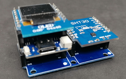
Wemos D1 Mini mit OLED Display & SHT30 Sensor
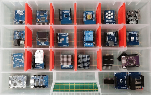
Shields für den Wemos D1 Mini Für den Wemos D1 Mini gibt es das Shield mit einem DS18B20, SHT30, DHT11 und DHT22 Sensor. Für diesen Beitrag verwende ich den Sensor SHT30. Das DS18B20 Sensor Shield ist am digitalen Pin D2 angeschlossen, an diesem liegt jedoch auch die I2C Schnittstelle an und diese benötigen wir für das OLED Display somit fällt dieses hier raus. Erhältliche Varianten des Wemos D1 Mini Den kleinen Mikrocontroller Wemos D1 Mini erhältst du derzeit in der Version 4.0 mit einem ESP8266. Wenn du jedoch mehr Leistung (CPU, Speicher) benötigst, dann kannst du auch auf eine Variante mit einem ESP32-S2 zurückgreifen. Beide Varianten kannst du für dieses Projekt verwenden!
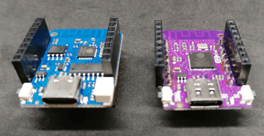
Wemos D1 Mini - Varianten Die beiden gezeigten Mikrocontroller habe ich dir bereits in separaten Beiträgen vorgestellt und einige Schaltungen präsentiert. - Vorstellung – Wemos D1 Mini V4 - Lolin S2 mini V1 im Test Technische Daten des Wemos D1 Mini Hier nun die technischen Daten des Wemos D1 Mini V4: Wemos D1 Mini V4Taktgeschwindigkeit80 / 160 MHzBetriebsspannung3.3 VAnzahl digitale Pins11Anzahl analoge Pins1Speicher4 MB SchnittstellenI²C, SPI, UARTUSB-AnschlussUSB-Typ-CVergleich der technischen Daten vom Wemos D1 Mini V4 & V3
Wie werden die Geräte miteinander interagieren?
Der Shelly verfügt über ein Relais, mit welchem man einen Verbraucher schalten kann. Der Shelly 1PM Mini Gen3 hat den Vorteil, dass dieser noch zusätzlich die Leistungsaufnahme messen kann. Mit dem Wemos D1 Mini wollen wir temperaturabhängig das Relais aktivieren / deaktivieren und auf dem OLED Display den Zustand anzeigen. Zusätzlich können wir auch die momentane Leistungsaufnahme anzeigen.

Der Vorteil dieser Schaltung liegt in ihrer einfachen Erweiterbarkeit. Zum Beispiel kannst du einen zusätzlichen Taster einbauen, um das Relais manuell ein- und auszuschalten, oder andere Sensoren integrieren. Mit einem IR Shield und der passenden Fernbedienung könntest du zudem weitere Geräte steuern und dir so ein kleines, intelligentes Dashboard schaffen.
Benötigte Ressourcen für dieses kleine Projekt
Schauen wir uns zunächst an, welche Ressourcen benötigt werden, um das kleine Projekt umzusetzen: - einen Shelly Mini - Shelly 1 Mini Gen* - Shelly 1PM Mini Gen3* - einen Wemos D1 Mini V4* - ein USB-C Datenkabel* - ein SHT30 Shield* - ein OLED Shield* - eine Dual Base Plate*
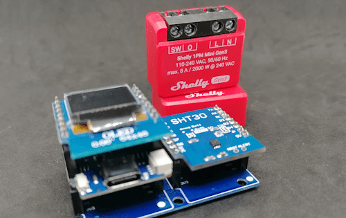
Shelly 1PM Mini Gen3 & Wemos D1 Mini Alternativ kannst du auch das Shield mit einem DHT11/DHT22 Sensor* verwenden. Hinweis von mir: Die mit einem Sternchen (*) markierten Links sind Affiliate-Links. Wenn du über diese Links einkaufst, erhalte ich eine kleine Provision, die dazu beiträgt, diesen Blog zu unterstützen. Der Preis für dich bleibt dabei unverändert. Vielen Dank für deine Unterstützung! Für den Shelly 1PM Mini Gen3 benötigst du noch ein Anschlusskabel, hier kommt es auf den Einsatzzweck an, in meinem Fall verwende ich ein 3x1,5mm² flexibles Kabel mit einem Schukostecker.
Programmieren des Wemos D1 Mini
Den Shelly habe ich bereits mit der Cloud verbunden und damit Zugriff auf die Verbrauchsdaten und dem Relais. In diesem Abschnitt möchte ich dir gerne zeigen, wie der Wemos D1 Mini programmiert werden muss um das Relais zu steuern & die Verbrauchsdaten anzuzeigen. Programm - Temperaturabhängige Steuerung eines Shelly Minis mit dem Wemos D1 Mini & SHT30 SensorHerunterladen Schritt 1 - steuern des Relais via Postman Mit dem Tool Postman kann man Requests an Services senden und eine Antwort auswerten. Dabei kann der Request mit allen benötigten Informationen (Header, Body, Parameter etc.) bestückt werden. Das gute ist, dass man dazu erst einmal nichts programmieren muss, sondern man kann zunächst die URL und die benötigten Eigenschaften des Requests ermitteln. //aktivieren des Relais http://192.168.178.141/rpc/Switch.Set?id=0&on=true //deaktivieren des Relais http://192.168.178.141/rpc/Switch.Set?id=0&on=false In der offiziellen, englischen Dokumentation zur Schnittstelle von Shelly findest du alle Informationen, welche Daten du abgreifen kannst. Schritt 2 - Auslesen der momentanen Leistungsaufnahme am Shelly 1PM Mini Gen3 via Postman Wenn du wie ich den Shelly 1PM Mini Gen3 verwendest, dann kannst du vom angeschlossenen Verbraucher noch zusätzlich Daten ermitteln. Du kannst neben dem aktuellen Energieverbrauch in Watt, die Stromaufnahme in Ampere ermitteln. Vom Stromnetz selber können wir die Spannung und die Netzfrequenz ermitteln. http://192.168.178.141/rpc/Switch.GetStatus?id=0
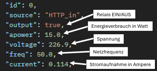
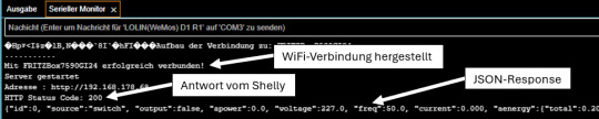
JSON Output von der Shelly API Schritt 3 - Auslesen der Daten am Wemos D1 Mini In der Arduino IDE kannst du dir Daten auf dem seriellen Monitor ausgeben lassen, das hat den Vorteil das wir nicht immer zwingend ein Display benötigen. Auf der seriellen Schnittstelle wollen wir zunächst die ermittelten Daten ausgeben. Schritt 3.1 - Aufbau einer WiFi-Verbindung Bevor wir etwas auslesen können, müssen wir eine WiFi-Verbindung zum lokalen Netzwerk herstellen. #include WiFiServer server(80); //Die Zugangsdaten zum WiFi-Netzwerk const char *ssid = "xxx"; const char *password = "xxx"; void initWifiModul() { Serial.println("Aufbau der Verbindung zu: " + String(ssid)); WiFi.begin(ssid, password); while (WiFi.status() != WL_CONNECTED) { delay(500); Serial.print("."); } Serial.println(); Serial.println("Mit " + String(ssid) + " erfolgreich verbunden!"); server.begin(); Serial.println("Server gestartet"); Serial.print("Adresse : http://"); Serial.println(WiFi.localIP()); } void setup() { Serial.begin(9600); initWifiModul(); } void loop() { // put your main code here, to run repeatedly: } Auf der seriellen Schnittstelle wird bei erfolg die IP-Adresse des Wemos ausgegeben. (Für diesen Beitrag nicht relevant.) Aufbau der Verbindung zu: FRITZBox7590GI24 ....... Mit FRITZBox7590GI24 erfolgreich verbunden! Server gestartet Adresse : http://192.168.178.68 Schritt 3.2 - Absenden eines HTTP-Request an den Shelly Zum Absenden der Daten benötigen wir einen HTTPClient, natürlich senden wir diesen Request nur ab wenn die WiFi-Verbindung besteht! #include String shellyServerAdress = "http://192.168.178.141/rpc/"; String shellyGetStatus = "Switch.GetStatus?id=0"; void sendHttpRequest(String url) { if (WiFi.status() == WL_CONNECTED) { WiFiClient client; HTTPClient http; http.begin(client, url.c_str()); int httpResponseCode = http.GET(); Serial.print("HTTP Status Code: "); Serial.println(httpResponseCode); String payload = http.getString(); Serial.println(payload); http.end(); } } Auf der seriellen Schnittstelle sehen wir nun neben dem Antwortcode vom Shelly (HTTP Status Code) noch zusätzlich den JSON Respond mit den gewünschten Daten.
Ausgabe der Daten eines Shelly 1PM Mini Gen3 auf dem seriellen Monitor Schritt 3.3 - Parsen des JSON Respond Um an die Daten im JSON Respond vom Shelly zu gelangen, müssen wir diesen jetzt parsen. Dafür benötigen wir die Bibliothek ArduinoJson. #include StaticJsonDocument json; char jsonResponse = ""; String relais = ""; String energieverbrauch = ""; String stromaufnahme = ""; String spannung = ""; String frequenz = ""; bool sendHttpRequest(String url) { if (WiFi.status() == WL_CONNECTED) { WiFiClient client; HTTPClient http; http.begin(client, url.c_str()); int httpResponseCode = http.GET(); Serial.print("HTTP Status Code: "); Serial.println(httpResponseCode); String payload = http.getString(); Serial.println(payload); payload.toCharArray(jsonResponse, sizeof(jsonResponse)); http.end(); return httpResponseCode == 200; } return false; } void printData(String text, String value, int index) { Serial.print(text); Serial.println(value); } void readData() { if (sendHttpRequest(shellyServerAdress + shellyGetStatus)) { DeserializationError error = deserializeJson(json, jsonResponse); if (error) { Serial.print(F("deserializeJson() failed: ")); Serial.println(error.f_str()); return; } Serial.println(); energieverbrauch = json + " W"; stromaufnahme = json + " A"; spannung = json + " V"; frequenz = json + " Hz"; relais = json == true ? "AN" : "AUS"; printData("Relais: ", relais, 0); printData("Energieverbrauch: ", energieverbrauch, 1); printData("Stromaufnahme: ", stromaufnahme, 2); printData("Spannung: ", spannung, 3); printData("Frequenz: ", frequenz, 4); } } Die Antwort vom Shelly (im JSON-Format) haben wir nun im Zugriff und können dort recht einfach auf die Daten zugreifen. Aufbau der Verbindung zu: FRITZBox7590GI24 ....... Mit FRITZBox7590GI24 erfolgreich verbunden! Server gestartet Adresse : http://192.168.178.68 HTTP Status Code: 200 {"id":0, "source":"switch", "output":true, "apower":14.5, "voltage":227.5, "freq":50.0, "current":0.112, "aenergy":{"total":2.884,"by_minute":,"minute_ts":1716113335}, "ret_aenergy":{"total":0.000,"by_minute":,"minute_ts":1716113335},"temperature":{"tC":55.5, "tF":131.9}} {"id":0, "source":"switch", "output":true, "apower":14.5, "voltage":227.5, "freq":50.0, "current":0.112, "aenergy":{"total":2.884,"by_minute":,"minute_ts":1716113335}, "ret_aenergy":{"total":0.000,"by_minute":,"minute_ts":1716113335},"temperature":{"tC":55.5, "tF":131.9}} Energieverbrauch: 14.500 W Stromaufnahme: 0.112 A Spannung: 227.500 V Frequenz: 50.000 Hz Schritt 4 - Anzeigen der Daten auf einem OLED Display Da wir die Daten vom Shelly nun ausgelesen haben, möchte ich dir zeigen wie diese auf einem OLED Display angezeigt werden. Für das ansteuern des OLED Displays am Wemos D1 Mini gibt es eine extra Bibliothek von Adafruit welche du bequem über den Bibliotheksverwalter installieren kannst.

Bibliothek für das kleine OLED Display von Wemos Die Adresse des OLED Displays ist 0x3c, mit dem kleinen Programm aus dem Beitrag Arduino I2C-Scanner für ESP8266 & ESP32 anpassen: Eine Schritt-für-Schritt-Anleitung kannst du am ESP8266 nach geräten suchen. An LOLIN(WEMOS) D1 mini Pro was recognized! The microcontroller has 1 I2C Interfaces! SDA: 4, SCL: 5 Scanning... I2C device found at address 0x3c! End. Ich würde dir empfehlen eine zuvor installierte Version der Adafruit_SSD1306 zu deinstallieren damit eventuelle Probleme minimiert werden. #include #include #include #include #define OLED_RESET 0 // GPIO0 Adafruit_SSD1306 display(OLED_RESET); void setup() { Serial.begin(9600); initWifiModul(); display.begin(SSD1306_SWITCHCAPVCC, 0x3C); display.setTextSize(1); display.setTextColor(WHITE); } void printData(String text, String value, int index) { Serial.print(text); Serial.println(value); display.setCursor(0, index * 10); display.println(value); } void loop() { display.clearDisplay(); readData(); display.display(); delay(2000); } Die Daten werden nun nicht nur auf der seriellen Schnittstelle ausgegeben sondern auch auf dem OLED Display. Da das Display sehr klein ist, kann hier keine zusätzliche Bezeichnung hinzugefügt werden und es werden lediglich die Werte angezeigt.
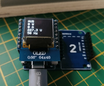
Daten eines Shellys (deaktiviert)

Daten eines Shellys (aktiviert) Schritt 5 - Auslesen des Temperatursensors SHT30 Wie eigentlich ganz am Anfang erläutert soll das Relais temperaturabhängig gesteuert werden, dazu stecken wir nun das SHT30 Shield auf den freien Platz der Dual Base Plate.
Wemos D1 Mini mit OLED Display & SHT30 Sensor Man könnte auch die die Shields untereinander auf einem Breadboard stecken. Jedoch strahlt jedes elektrische Gerät eine wärme ab wie auch der WiFi Chip des Wemos D1 Mini und wenn der Sensor zu nah an diesem ist, werden die Werte stark beeinflußt. Technische Daten des SHT30 Sensors Den SHT30 Sensor habe ich dir bereits im Beitrag Wemos D1 mini Shield: SHT30 Temperatur und Luftfeuchtigkeit Sensor vorgestellt und gezeigt wie dieser programmiert wird. Hier nun die technischen Daten Sensors: - Betriebsspannung: 3V bis 5,5V DC - Betriebstemperatur -40 °C bis 125 °C - Schnittstelle: I2C (0x44 Standard / 0x45 über Lötpunkte) - Temperatur: -40 bis +125 °C (± 0,3 °C) - relative Luftfeuchtigkeit : 0 % bis 100 % (± 2 %) Bibliothek zum auslesen des Sensors Für den Sensor gibt es von Wemos eine Bibliothek welche du dir Read the full article
0 notes
Text
0 notes
Text
remarkably, both!
Learning about designated initializers against my will but in a way that is entirely my fault.
12 notes
·
View notes
Text
youtube
how to create custom USB HID Device w/ USB HID Vendor Feature report for WEMOS Lolin S2 Mini WebHID API Live Demo Example data exchange (USB Host - USB Client): https://webhidvendor.blogspot.com/ WEMOS Lolin S2 Mini Custom USB HID - WebHID API Live Demo Example Web Interface ESP32 Arduino Core
#WEMOS#programming#how to#arduino#esp32-s2#tutorials#esp32#WebHID API#WebHID API Live Demo#Lolin S2 Mini#Custom USB HID#Vendor Feature report#Youtube
0 notes
Link
Looking for a good deal on esp32 wrover module? According to Espressif, the ESP-WROVER-32 is a powerful, generic WiFi-BT-BLE MCU module that targets a wide variety of applications ranging from low-power sensor networks. Explore a wide range of the best esp32 wrover module on Campus Componentto find one that suits you! Visit https://www.campuscomponent.com/products/esp32-wroom-32d-4mb-wi-443-d/2208614000001840752
0 notes
Text
🚀 NEW at Adafruit! Snap-on Enclosure for Sparkle Motion, ESP32-S2 Feather w/w.FL Antenna & Cytron MOTION 2350 Pro RP2350 controller! Protect LEDs, power IoT projects & build advanced robot friends, not robot enemies 🛠️💡🤖 Explore! http://adafruit.com/new
10 notes
·
View notes
Text
Flash Download Tool como Gravar Binários no ESP32
Este post é um tutorial de como gravar binários no ESP32 usando a Flash Download Tool disponibilizado pela Espressif.
Flash Download Tool é uma ferramenta disponibilizado pela Espressif para exportar arquivos binários para o ESP32. Baixar e instalar Flash Download Tool Antes de tudo é necessário baixar o programa Flash Download Tool no site de Espressif, após baixar, abra e defina chipType como ESP32. Além disso, haverá outras configurações mas não serão necessárias, por ultimo click ‘ok‘. Entendendo o Flash…
Ver no WordPress
#download flash tool exe#esp 32#esp32 arduino#esp32 arduino ide#esp32 board#esp32 bootloader#esp32 flash download tool command line#esp32 wroom#esp8266 flash download tool#espressif esp32 flash download tool#flash download tool esp32#flash download tool for esp32#flash download tools#flash download tools (esp8266 e esp32 & esp32-s2)#usb flash download tool
0 notes
Text
Shootout: Pi Pico vs ESP32(-S2) and STM32 Blackpill
Shootout: Pi Pico vs ESP32(-S2) and STM32 Blackpill
Shootout: Pi Pico vs ESP32(-S2) and STM32 Blackpill Category Main Description: The Raspberry Pi foundation spent a lot of money to create a new chip for makers and gives it away for cheap. If I believe all the fanboy’s videos, it is the most … TopTrengingTV Hunting the most trend video of the moment, every hour every day 24/7. Youtube Video Data Published At: 2021-01-31T08:00:07Z Tags: …

View On WordPress
#arduino#arduino project#beginners#Comparison#diy#do-it-yourself#eevblog#electronics#esp32#esp32 datasheet#esp32 project#esp32 tutorial#ESP32-S2#esp8266#esp8266 datasheet#esp8266 project#greatscott#guide#hack#hobby#how to#IOT#lorawan#main#nodemcu#Pi pico#project#Raspberry Pi#raspberry Pi Pico#RISC-V
0 notes
Text
A look at HackerBox 62
A look at HackerBox 62
Earlier this month, I received HackerBox 62: Watts Up. This month’s theme mostly seems to revolve around low power operations. I must admit I rarely worry about low power operations in my projects. But it is an important topic, and I can foresee some future projects where low power would be necessary. This post will look at what is included in HackerBox 62. ESP32-S2-WOOR V1.1 ESP32-S2 Included…

View On WordPress
1 note
·
View note
Text
My Programming Projects and Progress in 2020
My Programming Projects and Progress in 2020 #python #adafruit #circuitplaygroundexpress #Unity #gamedevtv #circuitpython #git
Back in 2019, when I did my programming retrospective I made a few predictions. How did those go? Work on my Extra Life Donation Tracker? Yup! See below!Write more C++ thanks to Arduino? Not so much. C# thanks to Unity? Yes, but not in the way I thought. I only did minor work on my game, but I did start a new GameDev.tv class.Learning Ruby? Well, I wouldn’t necessarily say I learned Ruby. I did…

View On WordPress
#Advent of Code#Arduino#Arduino MKR#btrfs#C#C++#Circuit Playground Express#CircuitPython#electronics#ESP32-S2#Game Development#Impractical Python#Matrix#Matrix-nio#Micfrosoft MakeCode#MS Makecode#Podman#Python Morsels#raspberry pi#raspberry pi zero w#Ruby#Scratch#Unity
0 notes